Project 1 Mechanical design of battery pack
Battery pack designing
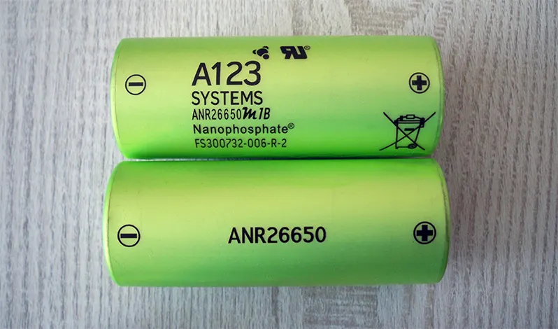
A123 high performance Nanophosphate lithium ion phosphate(LiFeP04) battery technology delivers high power and energy density combined with excellent safety performance and extensive life cycle,light weight and more compact package. The cells have low capacity loss and impedance growth over time as well as high usable energy over a wide range of Soc range. Allowing the system to meet extraordinary power and energy requirements with minimum pack oversizing.
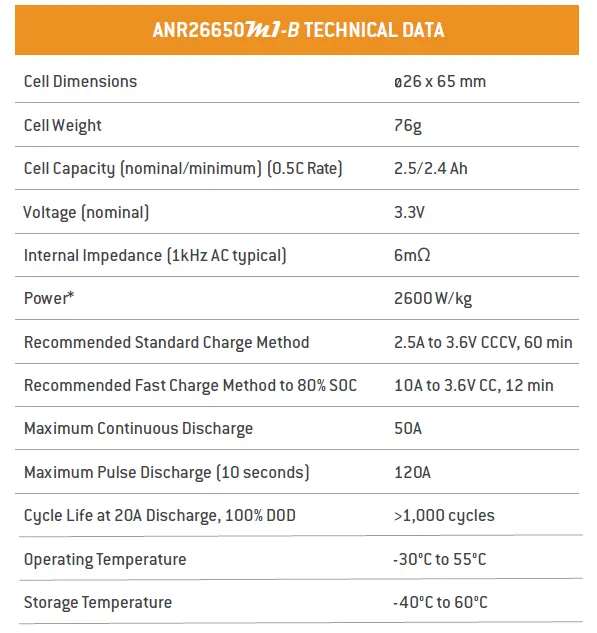
The technical data of this particular cell is shown below-
ANR26650M1-B means
A-> Zinc (+ve or anode electrode)
N-> Nickel(-ve or cathode electrode)
R-> Cylinderical (shape of the battery)
26-> 26mm (diameter of the cell)
650-> 65mm (height of the cell)
M1-B-> manufacture code (model name given by a manufacture)
Lithium iron phosphate chemistry
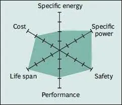
This chemistry is has a very good life according to the spider chart. The cell is amazing in terms of safety and performance. This is followed by 100% specific power which means that the cell can store a huge amount of power with less weight. The cost of this cell is little high but it is a very good chemistry overall.
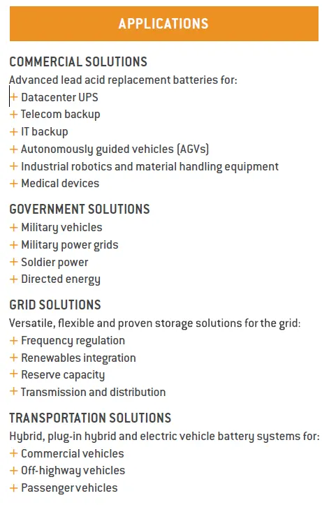
The performance graphs of the following cell are as follows:-
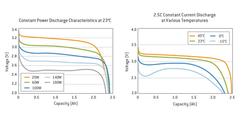
The constant power discharge characterstics show the graph between voltage and capacity. It is observed that if the current is discharged with less voltage then it begins with a pretty good nominal voltage and stays around the same voltage untill it reaches somewhere around 2.5A capacity which is the point of discharge. Discharging with high voltage makes the discharge curve to begin with a low voltage and makes it to stay in that region and also full discharge happens without reaching 2.5A of capacity.
The temperature effect is also shown in the next graph which is between voltage and capacity. Discharge done at safe temperature allows the battery to begin with the nominal voltage i.e. 3.4V and discharge linearly around that until it reaches the 2.5Ah capacity where it is dead. The opposite is observed in the case when the battery is discharged at high temperature. The discharge does'nt proceed with nominal voltage but way lower which is around 3V and has variation in the curve and also it gets discharged faster where it doesn't even reach 2.5Ah.
The cycle performance is shown below-
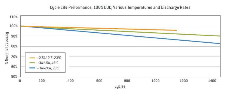
It is observed that the capacity reduces with no. of cycles. When the battery is operated at 2.5/-2/5 at 23 degree C, the cyle life decreases very slowly but the total number of cycle does not cross 1200 and the battery is rated as unfit for usage. One the other hand, discharging at 3A/-20A,23 degree C begins with more fall in the total capacity of the battery but the battery life is observed to be more than 1400. But here, the later capacity becomes around 90%. The remaining 10% capacity is unusable and this is call capacity degradaton.
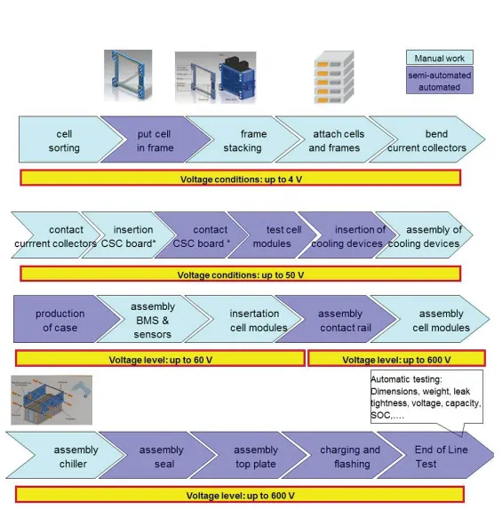
The method that are involved in producing a battery.
Electrical design
1)Determination of voltage,capacity,current.
2)High voltage isolation
3)Short circuit prevention
4)Efficient power delivery
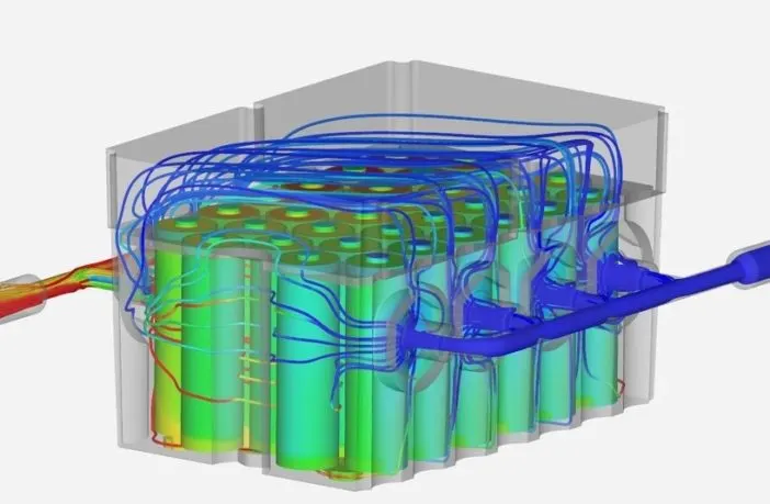
Thermal design
1)Improve pack efficiency
2)Reduction in thermal accidents
3)Improve pack life
Mechanical design
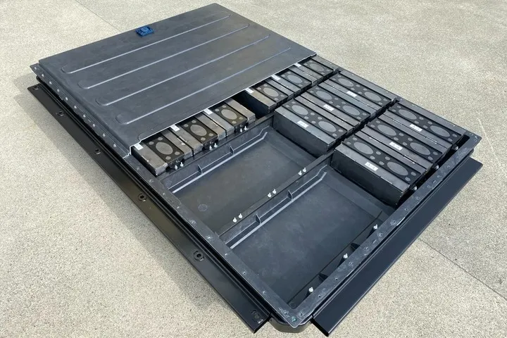
1)Strong and safe structure for extreme conditions.
2)Ease of assembly and service
3)Cost,productivity and reliabilty.
4)Light weight,compactness.
Battery management system design
1)Maintain the safe operating limits of the pack
2)Prevention of any dangerous conditons.
3)Control temperature of the pack
4)Communication and logisitics.
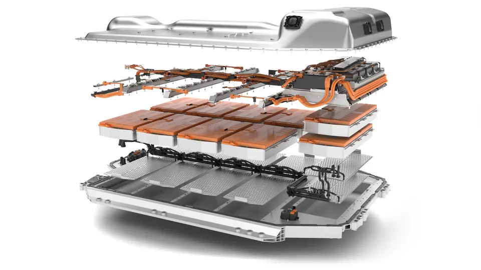
A battery consists of the following parts:-
1)Cell- This is the building block of the system which stores the energy in form of chemical. These convert the chemical energy into electrical energy which is used to drive the e-motor. The cells may be cylindrical,prismatic or pouch type depending on the design requirement. The cells operate on different chemical mixture amongst which the common type that is used in e-car is a rechargeable lithium-ion battery with any of the 6 chemistries. The chemistry depends on the performance output requirements.
2)Module- when many cells are connected together in series and parallel then this whole unit is called module.
3)Electrical connectors- These are busbars,wires, harnesses and other conductors which are used to build the series and parallel connections. The connections are done using laser welding and ultrasonic bonding. Busbars connections between the modules can be done mechanically by regular fasteners.
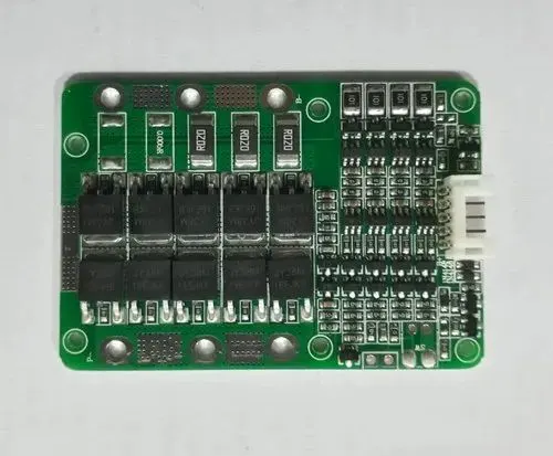
4)Battery management system- This is the brain of the battery pack which looks after each and every event that is going inside. The intension is quite simple which is to protect the battey pack from getting damaged. BMS looks after the voltage range, thermal range, current range. It monitors these parameters by reading the data, calculating the vitals and balances the cells for a safe operating zone.
5)Contactor system- This basically has a switch controlled by BMS. It can cut the electrical supply by turning the switch off between battery and high voltage bus which delivers high voltage current to the e-motor and other components.
6)Battery cooling system-The system which keeps the temperature of the pack in safe operating range. This is done by sending coolant through the complex channel which runs close to all the cells and unit which likely raise the temperature while the operating. The coolant takes the heat from the unit and carry it outside the pack and keeps the battery within safe temperatures.
7)Communication system- The system ensures that there is a proper communication between the e-vehicle and the electrical components. The basic one is CAN bus.
8)Battery case/shell- This is a structure which holds all the cell and other units in their places firmly and absorb some amount of shock and stress that is transferred from the rotating wheels to the battery pack. This also keeps the battery pack tidy in design. The battery pack can be designed as per the requirement just by changing the location of the cells. It also protects the pack from any environmental factors like moisture, water, sunlight,snowfall, dust etc. This prevents the pack from getting rusted or short circuit.
9)Battery spacer- These are a part of casing which isolate each cell from the other by keeping some space in between each cell. This helps in proper heat dissipation and also if any cell has some short circuit issue then it can't communicate with the adjacent cells.
Requirements
Voltage and capacity requirements
Battery voltage and capacity can be increased or decreased by adding or subtracting the cells. The overall voltage of the battery is the product of voltage of 1 cell and total number of the cell in chain. This doesn't affect the Ah of the battery at all but increases Wh or the total stored energy in proportion to the number of cells. For more voltage requirements, the battery is added with cells in series and for capacity or charge requirements, more cell are connected in parallel. In parallel arrangement, the overall Ah along with Wh is increased without disturbing the battery voltage. The capacity of the battery is the capacity of 1 cell with the no. of cells in parallel. It is always good if the no. of cells are kept as low as possible for simplified and compact design. It is always kept in mind while constructing the battery pack that the cells used are of the same slot of manufacture or all the cells were manufactured at the same time. This is important as no two cells are identical in performance and to make the output difference to the least, cells manufactured at the same time are chosen for a particular pack construction.
Cell configuration
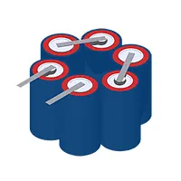
The dimension and shape of the pack is as per the car design and available space. There are different shapes available for the maker to choose. Prismatic cells provide the best space management but on the other hand cylindrical cell gives the best cooling management. Pouch cell has more freedom in specifying the shape of the battery with compact design. the shape of the cell is done to achieve a compact pack design with least inter-connection between the cells.
Battery circuit configuration
Battery electronics plays a key role in proper supply of the current and other operations. These may be a circuit or a protection device, charge gauge,indication light that start functioning when the battery is in use. A battery with multi-cell configuration requires cell balancing and communication. These circuits are arranged after the basic arrangement of all the cells is done. These are arranged in such a way that they don't get in touch with each other which may lead to short-circuit. These circuits also need to be operated at save temperatures in order to make the battery optimum performance.
Software
This plays a keen role in the designing part. Software is basically the command that is given by the brain to the system. The battery has to be configured to operate automatically without any human intervention. All the systems are pre-set to operate within the range and on any violation, the system has to be shut-down. This is done automatically with the help of a software which includes a language that the system understands and functions accordingly. BMS is basically the software that does the job of keeping the cell within safe voltage range, temperature etc. The system has to communicate with all the other system of the e-vehicle for proper supply of energy and monitor current battery status.
Internal connections
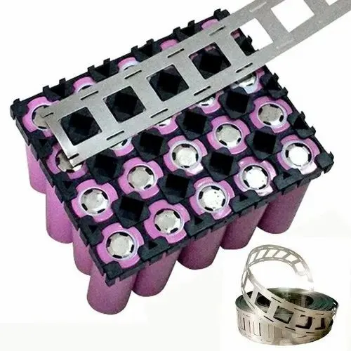
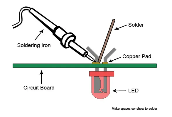
Low power cells are connected together by nickel H-stripe which are welded to the terminals. But this cannot be done by soldering as this process involves high amount of heat applied to the components and which may damage the connections by melting them. Modern welding techniques involve control current and heat which is precise to such a level that it can focus on a very small area. Welding also provides a strong and low resistance joint. The stripe may have complex shape which have to be welded on to the stamped on to the terminal. Bus bar are used by high power cell made of solid copper. The electronic components are usually mounted on the printed circuit board which are flexible and also cost high. The reason why they are still used is that they save a large amount of weight and space and make the connection tidy. This eliminate different types of connections for different components as the board has already connected most of the components on it.
External connection
These are basically the connection involved at the terminal like contacts. The material used to make the contacts depend on the frequency of the battery getting connected and disconnected with design of the battery. Gold plated contacts, flying lead with spade terminals are used for low power connectors. This is because gold has low contact resistance and doesn't oxidize. Metal tabs are used in case of pouch cells. For safety purpose, keyed terminals are used which prevent connection to incorrect chargers or loads. This saves the battery from short circuit due to high voltage supply.
Thermal design
The operation in the battery where current and voltage are involved go through some serious thermal problem. This makes the battery mandatory to have a cooling system which provides air, water or any coolant to keep the battery at safe operating temperatures. The system has a channel through which the coolant flows. A heat exchanger which has a fan to cool down the coolant when it comes with the tranferred head by the battery system. This is the reason why layout of the cell is conductive so that it could manage the heat flow within the pack.
Battery casing/housing
The battery casing should provide both electrical and mechanical interfaces. The overall cost of the housing should be less but also the material used to build it should be strong enough to withstand all the stresses and forces while operating in an e-car. It should also be safe enough in case of short circuit. In short circuit or thermal runaway, the battery should atleast be strong enough to keep itself isolated with other electrical components to avoid a big explosion. It should be tight enough to stay in its place at the time of operation and doesn't expand or contract which is seen in case of metal. Tolerances are taken in account in order to design a housing. Thermal dissipation channels are provided which help the heat generated by each cell to dissipate out of the battery pack. The battery housing should allow easy access to the cells and it should also allow the use of other cells of same dimension in case if there is any requirement. In many cases, pouch cells get swelled due to overcharging. The housing should be designed in such a way that it has some space in case the cell go through such problem.
Manufacture of a lithium ion cell
Lithium is taken out from the Earth crust and then extracted from the salt-flat brines through a process of evaporation and chemical recovery. The electrode mixing is the done first using a giant mixer lithium slurry is blended. Then coating is done on the metal ion collector. This involves coating on anode and cathode which are electrons and protons collector. Anode is coated with copper while cathode is coated with aluminium. The next step involves drying in which these coated electrodes are dried up to 302F. The chamber is humid controlled with less than 0.5% of humidity. Drying actually reduces cracking of the elctrode surface. This process also makes the lithium to spread evenly on the electrode with great precision. Cutting the long sheet of electrodes into stripe is done next. The tools used over here are highly precised like lazer tools etc. This is actually necessary to avoid any blur formation and freying edges while cutting. The cells are stacked together with all the electrodes and elctrolyte. These formed cells are then dried for 24 hours. This reduces blistering and improves cell quality. Aging of the cells is the longest stage in manufacturing process. The cells are charged and discharged several times to activate the cells. The last stage is grading the cell where the cell is marked with the charge, discharge, capacity, resistance etc. In the end, the cells are ready to be transported for selling.
Mechanical design processing
Cell datasheet that
The cell used to form the battery pack=ANR26650MIB
Required energy capacity of the pack=18kWh
Cell parameters as per datasheet
Cell weight= 76g
Cell capacity= 2.5Ah
Nominal voltage= 3.3V
Cell diameter= 26mm
Cell height= 65mm
Cell price= $6.55= Rs516.72
Suppose the total pack voltage is 400V
Pack capacity = (Energy capacity/Pack voltage)=(18000/400)=45Ah
No.of cell in series= (Total voltage/voltage of 1 cell)=(400/3.3)=121.21 or 122 cells
No. of cell in parallel= (Total pack capacity/cell capacity)=(45/2.5)=18cells
Total no.of cell in the pack=no.of cell in series*no. of cell in parallel=(122*18)=2196cells
length of the pack=(diameter of 1 cell* no. of cell in series)=(26*122)=3172mm or 3.17m
width of the pack=(diameter of 1 cell* no. of cell in parallel)=(26*18)=468mm=0.468m
height of the pack=(height of 1 cell)=65mm or 0.065m
weight of the pack=(Weigth of 1 cell*total no. of cells)=(76*2196)/1000=166.89 or 167kg
Total area of the pack=(length*width)=3.17*0.468=1.48mm^2
Total volume of the pack=(Area of the pack*height)=1.48*65=96m^3
Specific Energy density= (Energy capacity/weight)=(18000/167)=107.78 Wh/Kg
Volumetric energy density=(Energy capacity/volume)=(18000/96)=187.5Wh/L
Total cost of the pack= (cost of 1 cell*total no. of cells)=(516.*2196)=Rs 11,133,136
The battery pack cost is way too high to be used in Indian market as the cells are produced outside India. The cost is equivalent to a sedan car which is why the cell price has to be low to design a battery pack of an affordable price. May be if the same cell is produced in India, the cost would be very less than this particular one.
Construct a battery pack with the same cell
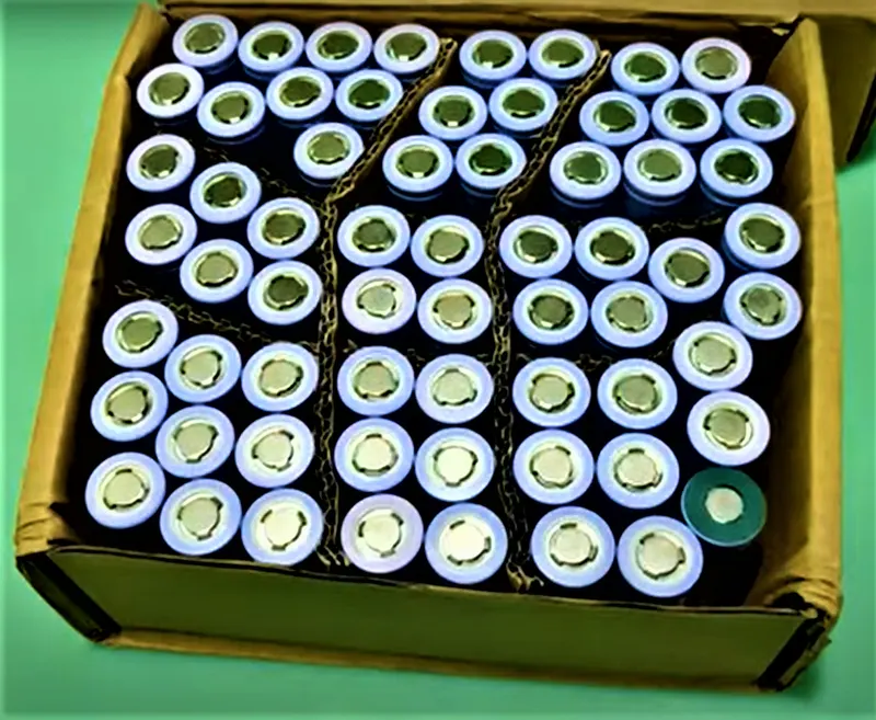
Keep all the cell neatly in a box so that there is no cell misplaced or lost.
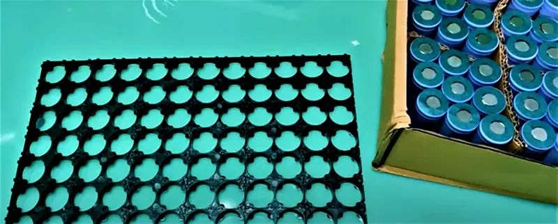
Take the spacers(here 2 cell spacer) and connect them to form an array of cells according to the calculated no. of cells in series and parallel. Here, it is 122 cells in series and 18 cells in parallel so the array would be 122*18. Prepare the spacer in the same manner which would act like the base of the battery pack.
Fix a cap at +ve terminal side of each cell which is very important for safety purpose. The process is also known as capping. Length wise the cell with all the positive terminal facing the sky should be fixed in the spacer firmly. These cells would be used for parallel connection. Similarly, arrange the cells width wise in such a way that 1 cell should have +ve terminal facing the sky and the next one facing the floor. Let the same pattern repeat till the end. These cells would be used to make series connection.
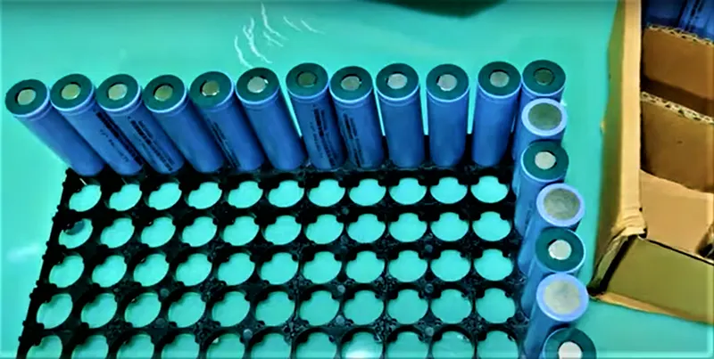
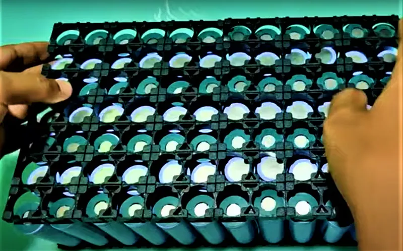
Now prepare the same type array of spacer as it was prepared earlier. This would act as the top support of the pack and protect the cells from any direct impact and also keep the cells in their fixed place. Now the set up somewhat looks like a battery pack. Make sure that the battery holder is tightly fixed on the top of the cells.
Now, take a H- type stripe nickel stripe sheet and cut it according the total number of cells. This stripe will connect the cells in terms of electrical connection.
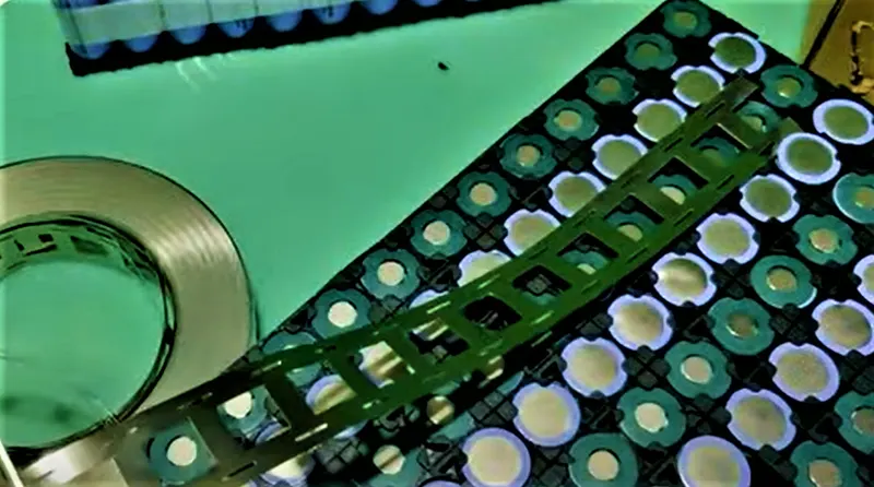
The stripe is kept accurately on the battery that are to be connected in series. This will help in proper connection of all the cells.
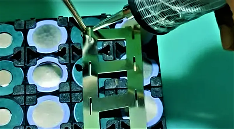
The stripe is connected with the help of spot welding which is focused and doesn't melt the nickel stripe. At the end of the connection, there has to be one +ve terminal output and -ve terminal output which is done by leaving two ends of nickel stripe open from both the sides of the pack.
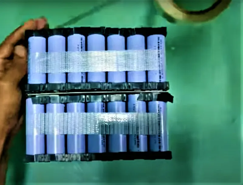
The so called pack is applied with some tap. Tapping is done in order to give extra support to the battery from lateral sides.
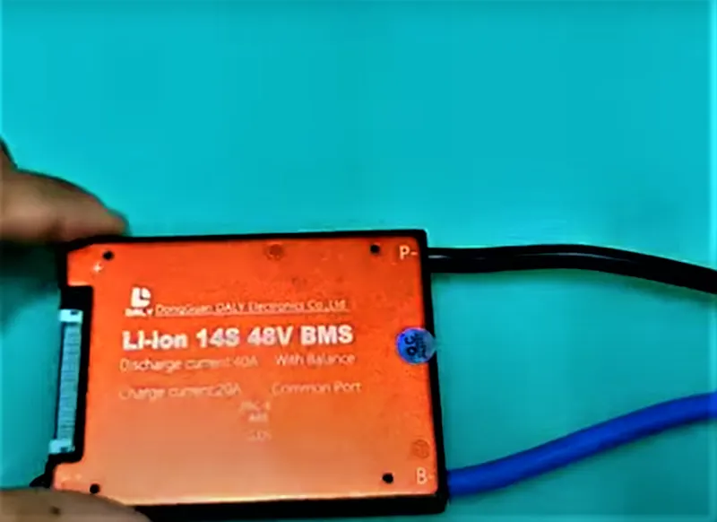
To balance and control the whole pack, battery management is taken and inspected well. This is because different BMS are design for a particular battery pack depending on the parameters.
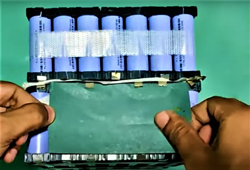
To fit the BMS on the battery pack, barley paper is used and is pasted on any of the 4 sides. Barley paper acts as an insulation between 2 electrical units and isolates them and prevents from any short circuit or undesirable wire contact. BMS can be fitted on any side of the pack depending on the design of the battery pack.
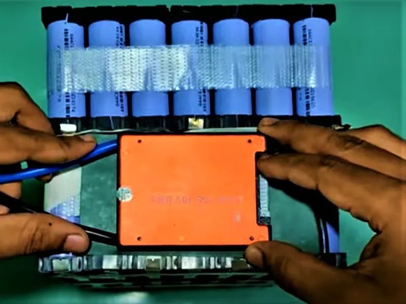
BMS is pasted on the the barley paper with the help of a double side 3M tape. Press the BMS on the pack so that it gets pasted tightly without any loose contact.
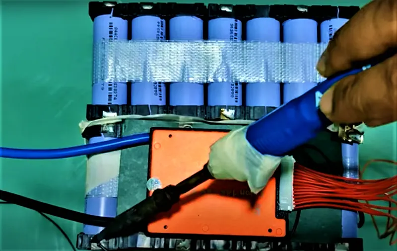
The -ve abd +ve side of the battery pack is connected to the BMS with the help of wires.
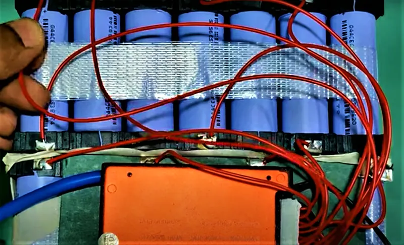
Connect all the wire and begin with the 1st cell and connect all the cell with BMS. After the connection is done
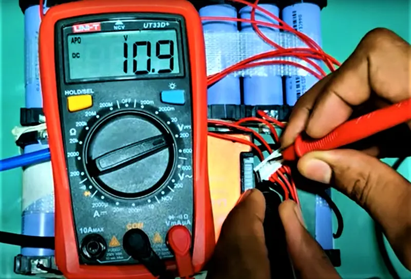
In the end of the process, all the cells are checked with the help of a multimeter. The cell is tested taking the zero cell as refrence and later testing all the remaining cell one by one. This helps to know whether the wires have been connected properly or not. Multimete -ve terminal probe is connected to the -ve wire and +ve probe is connected to the +ve wire. The +ve probe is moved to different cell connections where the voltage would add till the end figure is not acheived. This is a checkup of the circuit for safe operation.
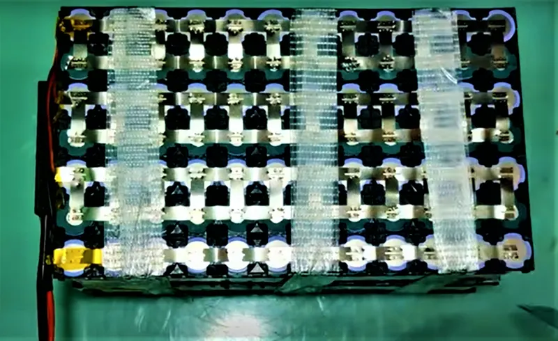
The battery pack is completed with all the components fixed firmly on the unit and all the wirings have been checked and tested ok.