Project 1 Mechanical design of battery pack
"Project 1 Mechanical design of battery pack"
AIM:
To design a battery pack for 18kWh.
OBJECTIVE:
To prepare a detailed battery pack drawing along with its enclosure.
Battery pack capacity: 18 kWh
Cell: ANR26650M1-B
METHODOLOGY:
1) To build the Battery pack for any Electric Vehicle, we have to calculate the first proportion of power then motor power and depending on that we will model the battery pack so we know how much power we required which is 18kWh.
2) For the 18kWh battery Pack we have to calculate how many cells are parallel and how many cells are in series.
3) After calculation of series and parallel combination we have to calculate the proper Geometry and topology consideration for assembling batteries.
4) After Assembly we need to find a proper enclosure for the battery pack for thermal consideration and other physical damages.
BASIC THEORY:
The high voltage battery is one of the most important components of a battery electric vehicle (BEV). The battery parameters have a significant influence on other components and attributes of the vehicle, like:
- maximum traction motor torque
- maximum regeneration brake torque
- vehicle range
- vehicle total weight
- vehicle price
Pretty much all major aspects of a pure electric vehicle (EV) depend on the parameters of the high voltage battery. For our electric vehicle battery design we are going to start from 4 core input parameters:
- chemistry
- voltage
- average energy consumption of the vehicle on a driving cycle
- vehicle range
A battery consists of one or more electrochemical cells (battery cells) which are converting chemical energy into electrical energy (during discharging) and electrical energy into chemical energy (during charging). The type of elements contained within a battery and the chemical reactions during discharging-charging events define the chemistry of a battery.
A battery cell consists of five major components: electrodes – anode and cathode, separators, terminals, electrolytes, and a case or enclosure. For automotive applications, there are different types of cells used Individual battery cells are grouped into a single mechanical and electrical unit called a battery module. The modules are electrically connected to form a battery pack.
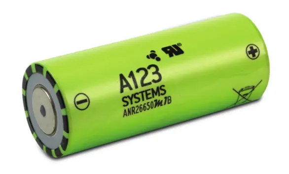
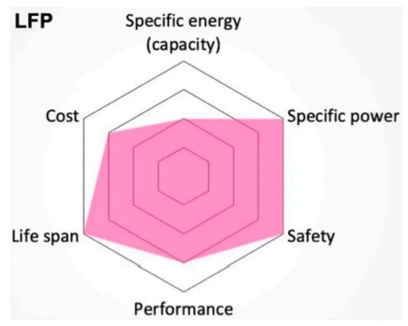
The cell which is given for the design of the battery pack is designed and manufactured by A123 systems. It is a high-performance Nanophasphate Lithium iron phosphate (LiFePO4) battery technology that delivers high power and energy density combined with excellent safety performance and extensive life cycling in a lighter weight, more compact package. The cells manufactured by this company have low capacity loss and impedance growth over time as well as high usable energy over a wide SOC range, allowing our systems to meet end-of-life power and energy requirements with minimal pack oversizing.
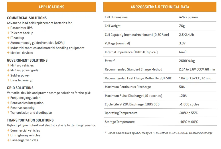
To calculate all the parameters, we need the data of the cell ANR2665031-B, for that, we have to check the datasheet of the cell. The following figure shows the basic characteristics of the cell given in its datasheet.
The provided battery cell type is ANR26650M1-B and its datasheet is used to get all the required information about it. After that, we will figure out how many cells we require to achieve the said 18 kWh capacity and also the configuration of their connection. In the end, a detailed battery drawing along with its enclosure is given to understand its working of it more deeply.
Technical Specification ANR26650M1B -
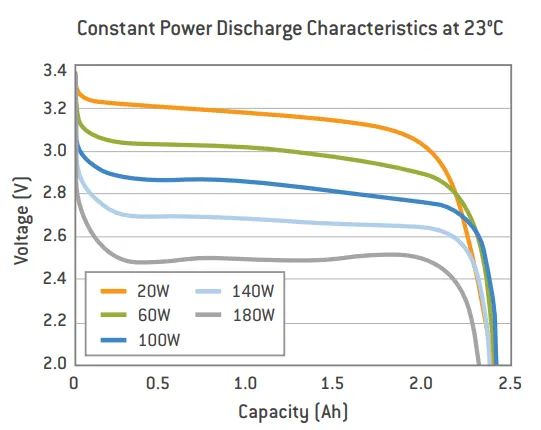
The following are the constant power discharge characteristics of the cell at 23°C temperature. These characteristics are drawn for different power ratings of the cell. If we observe the plot, as the power of the cell increases the voltage and its discharging characteristics are decreasing.
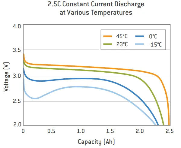
The following figure shows the 2.5C rate Constant current discharge characteristics at different temperatures, If we observe the plot it can be said that the cell characteristics vary with respect to the temperature changes. So we have to operate the cells within their nominal temperature zone.
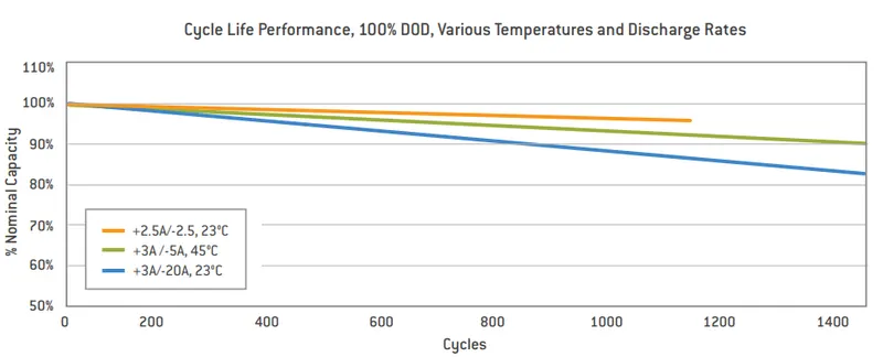
The following figure shows the cycle life performance, 100% DOD (Depth Of Discharge), various temperatures, and discharge rates of the cell.
The battery parameters have a significant influence on other components and attributes of the vehicle, like Maximum traction motor torque, Maximum regeneration brake torque, Vehicle range, Vehicle total weight, and Vehicle price. So based on all these parameters we have to design a battery pack. All major aspects of a pure electric vehicle depend on the parameters of the high voltage battery.
A battery pack consists of one or more electrochemical cells which are converting chemical energy into electrical energy during discharging and electrical energy into chemical energy during charging. There are several types of batteries used in hybrid and electric vehicle propulsion systems but we are going to consider only Lithium-ion cells. The main reason is that Li-ion batteries have higher specific energy (Wh/kg) and specific power (W/kg) compared with other types. The following plot shows the Ragone chart of different cells. The Li-ion shows its best characteristics compared to other cells.

The voltage level of the battery determines the maximum electrical power which can be delivered continuously. As power is the product of voltage and current. The higher the current, the bigger the diameter of the high voltage wire and the higher the thermal losses. For this reason, the current should be limited to a maximum, and the nominal power obtained by having a higher voltage. For our modeling of the pack, considering the nominal voltage of 264V. All high voltage battery packs are made up of battery cells arranged in strings and modules. A battery cell can be regarded as the smallest division of the voltage.
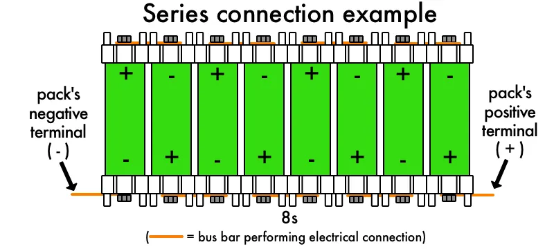
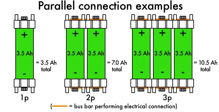
Individual battery cells may be grouped in parallel and/or series as modules. Further, battery modules can be connected in parallel and/or series to create a battery pack. Depending on the battery parameters there may be several levels of modularity. The total battery pack voltage is determined by the number of cells connected in series. The current capacity of the battery pack is determined by the number of cells connected in parallel. The following figures give information on series and parallel connections.
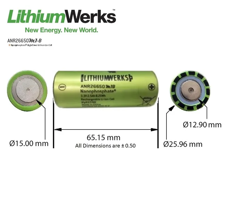
Based on the cell parameters provided by the manufacturers, we can calculate the energy content, volume, gravimetric density, and volumetric density for each cell. The following figure shows the dimensions of the ANR2665031-B cell.
* Details of Cell: ANR26650M1-B:
Nominal Rating:
- voltage: 3.3 volts
- capacity: 2.5Ah
- energy: 8.25Wh
- specific power: 2600W/kg
- impedance(1KHz AC typical): 6 mΩ
- cell type: 26650 lithium-ion power cylindrical cell.
Discharging:
- max.continuous discharge: 50A
- max pulse discharge current > 50% SOC (10sec): 120A
- minimum voltage: 2 volts
- temperature: -30 to 55 degree celsius
Charging:
- recommended std. charge: 2.5A
- max charge rate: 10A
- max pulse charge current<50% SOC (10sec) : 25A
- float voltage: 3.45 volts
Mechanical parameters:
- diameter: 25.96 +/- 0.5 mm
- length: 65.15+/- 0.5 mm
- mass: 76g
* Calculation as per assumptions: 18 kWh battery pack.
The calculation for designing an 18 KWh battery pack basically 18 KWh is the energy required to achieve the vehicle in its proper range and it depends on the voltage(V) and amp-hr capacity(Ah).
1] single cell energy(Wh) [the value of single cell energy is used to calculate the total energy of the battery pack]:
single cell energy(Wh)= cell capacity(Ah)* cell voltage(V)
= 2.5Ah *3.3V
= 8.25 Wh
2] single cell volume calculation:
single cell volume = pi(r^2)*h
= 3.14(0.013^2)*0.065
= 0.03451 m^3
3] single cell energy density:
A] volumetric energy(Wh/m^3) = single cell energy / volume of each cell
= 8.25Wh / 0.03451 m^3
= 239.0611 Wh/m^3
B] gravimetric energy(Wh/kg) = single cell energy / single cell mass
= 8.25Wh / 0.076 kg
=108.5526 Wh/Kg
Calculation of high voltage battery pack:
For the design and calculation of the battery pack here, I assume a vehicle to achieve 200km in an 18 KWh battery pack also I assume 145.2 nominal voltage for series connection.
we assume that,
vehicle range = 200 Km
battery pack capacity = 18.1210KWh
now,
4] we will calculate per Km average energy requirement = 18120.96 (Wh)/200 (Km)
= 90.60 Wh/Km
Therefore,
battery pack total energy = average energy * km
= 90.60Wh * 200km
= 18120.96 Wh
let's assume nominal voltage for series connection= 145.2 V basically this depends upon the motor power, we can decide the value according to the motor.
5] number of cells connected in series = nominal voltage of series connection/nominal voltage of a single cell
= 145.2V/ 3.3V
= 44 cell
44 cells will be connected in a series connection to provide a proper voltage.
6] energy for battery pack(Wh) = number of cells connected in series * single cell energy
= 44* 8.25Wh
= 363 Wh
7] number of cells connected in parallel = battery pack total energy(Wh)/energy for battery pack(Wh)
= 18120.96 Wh/363 Wh
= 50 cells
50 cells will be connected in a parallel to provide a proper capacity power.
8] battery pack total energy(Wh) = no. of cell connected in parallel * energy for battery pack
= 50* 363 Wh
= 18.150 KWh
9] battery pack capacity(Ah) = no. of cell connected in parallel * single cell capacity(Ah)
= 50*2.5 Ah
= 125 Ah
the value of battery pack capacity is used for the total power required by the vehicle.
10] The total number of cells for battery pack = no. of cells connected in parallel * number of cells connected in series
= 50*44
=2200 cells
2200 cells will be used to make a complete battery pack.
11] mass of battery pack = total number of cells for battery pack * mass of single cell
= 2200 * 0.076 kg
= 167.2 kg
167.2 kg is the total weight of cells connected in parallel and series
12] total volume of the battery pack = total number of cells for battery pack * volume of single cell
= 2200 * 0.0345 `m^3`
= 75.9 `m^3`
75.9 `m^3` is the volume occupied by the total cells used in the battery pack.
13] cell peak current(A) = C rate(max pulse charge current)* single cell capacity
= 20* 2.5
= 50A
14] battery pack peak current(A) = cell peak current(A) * no. of cell connected in parallel
=50*50
= 2500A
15] battery pack peak power(W) = battery pack peak current(A) * voltage of series connection
= 2500 A * 145.2
= 363 KW
16] cell continuous current(A) = C rate(max continuous charge current)* single cell capacity
= 10* 2.5
= 25A
17] battery pack continuous current(A) = cell continuous current(A) * no. of cell connected in parallel
= 25*50
= 1250 A
18] battery pack continuous power(W) = battery pack continuous current(A) * voltage of series connection
= 1250 A * 145.2
= 181.5 KW
Cell Design and Assembly of Battery Pack:
* Single Cell Design:
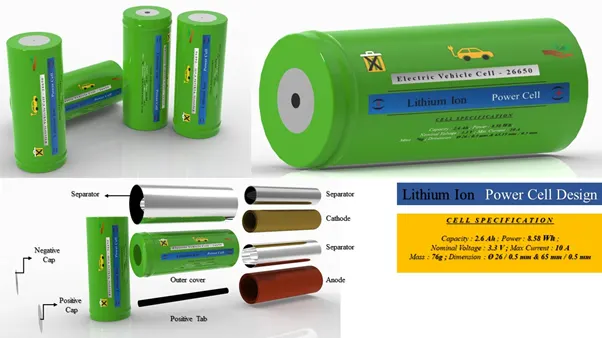
A Cell is basically consisting of Anode, Cathode, Separator, Positive Cap, Negative Cap, and Gasket -
The arrangement design of the single-cell is shown below -
*Design of cell holder (Bottom and Top) :
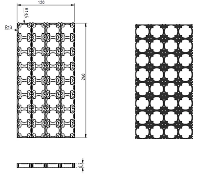
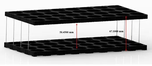
The main function of a battery holder is to keep cells fixed in place safely and securely also it is used to keep cells in a proper arrangement so that there will be a decrease in mechanical vibration, and have a better thermal runway in between the gaps of the cell. Most of the cell holder is made up of polypropylene or nylon bodies rated for 80–100 °C.

*Choosing the Right Battery Strips:

To make the battery pack, you have to connect these cells together by means of Nickel strips or thick wire. Generally, Nickel strips are widely used for this. In general two types of nickel, strips are available in the market: nickel-plated steel strips and pure nickel strips. It will be wise to buy a pure nickel cell. It is a little bit costlier than nickel-plated steel, but it has much lower resistance. Low resistance means, less heat generation during the charging and discharging, which leads to longer useful battery life.
Nickel strips come with different dimensions and lengths. Choose the strips according to the current rating.
#Nickel Strips:
- Nickel strip is generally used in battery building. It's due to its efficiency of usage in spot welding and soldering as well as its high corrosion resistance over time. It has good properties and excellent resistance to many corrosive environments.
- The pure nickel will never get rust after it is applied to battery packs. It won’t affect the current transfer between batteries.
- Pure nickel strips are the material you want, but many vendors swap out it for nickel-plated steel strips, which are poorer and have greater resistance – not suitable for most battery projects.
- 100% pure nickel strip. verify all of our strips to assure that you are getting the high-quality pure nickel.
- It also solders incredibly quickly, so you can weld them onto your existing busbar connections to raise the supply of current you can pull through the busbars. The benefits are nearly limitless.
*Spot Welding Vs Soldering:
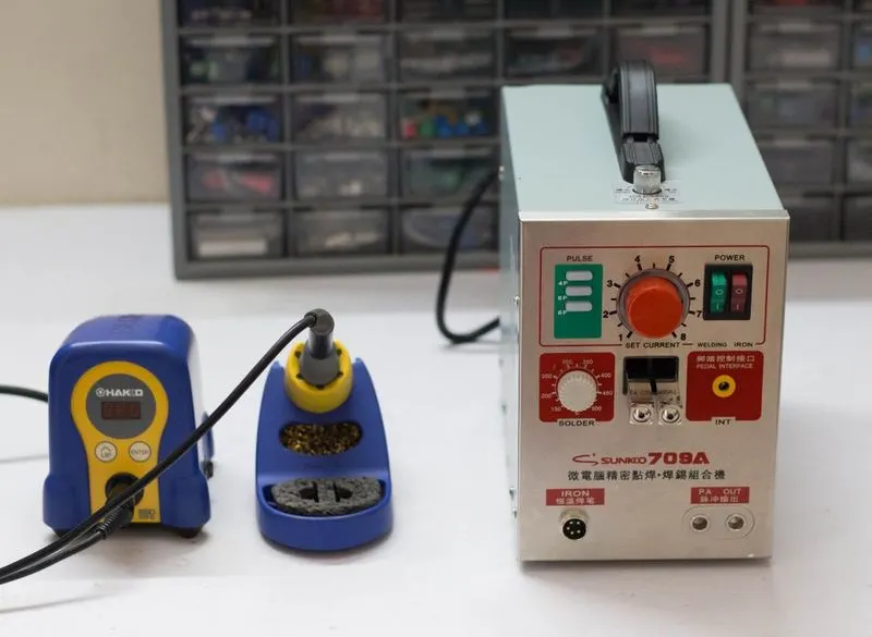
There are two options to connect these cells together: 1. Soldering 2. Spot Welding
The best choice is always Spot welding, but Spot Welder is much costlier than a good quality Soldering Iron.
Soldering :
Why Spot welding is preferred over soldering? The problem with soldering is that there is a need to apply a lot of heat to the cell and it doesn’t dissipate very quickly. This enhances the chemical reaction in the cell which damages the cell's performance. Ultimately the cell will lose some capacity and life of the cells.
Instead of buying a costly Spot Welder, soldering the nickel tabs to the cell by following some precautions and tricks will be useful:
1. To minimize the contact time of the soldering iron on the cell, make sure the surface is scuffed up sufficiently and you use plenty of flux to allow for fast solder flow.
2. It is better to have a good quality high wattage ( min 80W ) iron with good thermal capacity so it can deliver the heat to the joint quickly to avoid holding the iron to the battery for ages and letting the heat seep into it, causing damage to the battery.
Spot Welding :
The reason we spot weld is that it securely joins the cells together without adding much heat to them. There are two grades of spot welders currently available in the market: hobby grade and professional grade.
*Check the Cell Voltage:
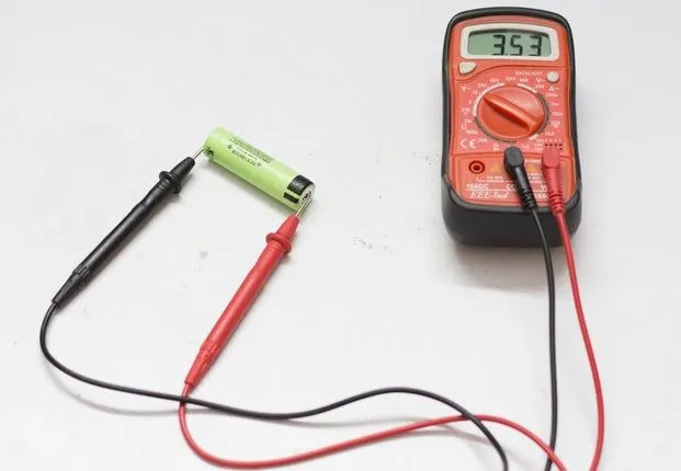
Before connecting the cells in parallel, first, check the individual cell voltages. For paralleling the cells, the voltage of each cell should be near to each other, otherwise, a high amount of current will flow from the cell with a higher voltage to the cell with a lower voltage. This can damage the cells and even result in fire on rare occasions.
If using brand new cells, the cell voltage is near 3.5 V to 3.7 V, joining them together is much easier. But if we use an old laptop battery, be sure the cell's voltage is nearly the same, otherwise, charge the cells to the same voltage level by using a good Li-Ion Battery Charger.
*Assemble the ANR26650M1-B Cells:
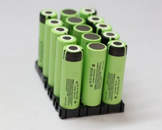
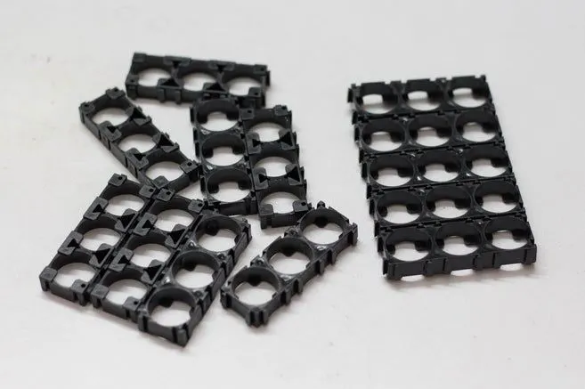
From the previous step, it is clear that our battery pack is made up of 44 parallel groups connected in series ( 44 x 3.3V = 145.2 V), and each parallel group has 50 cells (50 x 2.5 Ah = 125 Ah). Now we have to arrange the 2200 cells properly for making the electrical connection among them and with the BMS board.
Place the first parallel group of cells (50 nos) positive side up, then place the second parallel group negative side up, and then finally the last parallel group positive side up. For better understanding, refer to the above picture.
Now assemble the cells to make the pack by using hot glue or by using a plastic ANR26650M1-B battery holder. The main advantages of using these cell holders are
1. We can make a custom pack of any size according to your requirement. It's like solving a puzzle.
2. It provides space between the cells, which allows fresh air to pass and the battery gets cooled easily.
3. It makes our battery pack solid and reliable.
4. It provides safety and anti-vibration to our battery pack.
* Spot Weld the Nickel Strips:

Now it is time to know the procedure for using the Spot Welder. The Spot welder has three welding choices: fixed welding head, fixed welding head with foot switch, and movable spot welding pen with the footswitch. Here, we will use the second option. Before welding, we have to prepare the nickel strips and welder.
Cut the nickel strips :
Lay the nickel strip on top of the 50 cells (parallel), ensuring that it covers all the cell terminals, leave 10mm excess strips for connecting it to the BMS, and then cut it. For series connection cut small nickel strips as shown in the figure.
Connect the first parallel group's negative terminal to the positive terminal of the second group and then the negative terminal of the second group to the positive terminal of the third group.
Weld the Battery Strips :
This spot welder can be used to weld pure nickel as well as nickel-plated steel strips. We have to adjust the welder pulse and current knob according to the thickness of the nickel strips.
For 0.15 mm nickel strips, press the pulse knob 4P and the current knob to 4-5. Similarly, for the 0.2 mm nickel strip, press the pulse knob 4P,6P, and current knob to 7-8. Make sure the welding pen is compressed with the nickel strip and battery terminal, then press the footswitch. We will notice a small spark and two-dot mark on the strip.
Successful Welding :
We can check the weld quality by pulling on the nickel strip. If it doesn’t come off with hand pressure or requires a lot of strength, then it’s a good weld. If we can easily peel it off, then we have to increase the current.
Safety: Before starting the spot welding, always wear safety goggles.
*Adding the BMS:
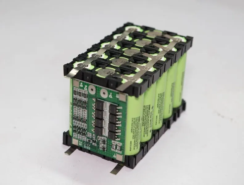
A battery management system (BMS) is an electronic system that manages a lithium battery pack.
Connect the BMS as shown in the figure. The BMS has four soldering pads: B-, B1, B2, and B+. We have to connect the first parallel group negative terminal bus to the B- and the positive terminal bus to the B1. Similarly the third parallel group negative terminal bus to the B2 and positive terminal bus to the B+.
We can spot weld the nickel strips to the BMS or solder them to the PCB pad. I preferred to solder the nickel strips to the PCB for a sturdy connection. First, apply soldering flux to the PCB pads and the end of the nickel strips. After that in all the pads by applying a little amount of solder and then solder them together.
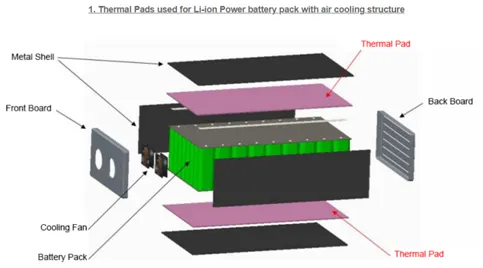
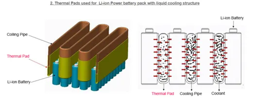
*Install cooling structures for air cooling/ liquid cooling as shown:
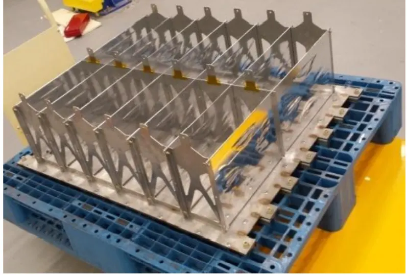
* Design of Lower floor case for battery pack:
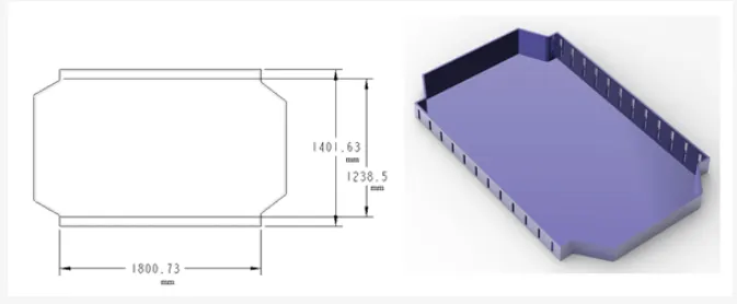
Basically, the lower case is a part that is fitted in an electric vehicle for the assembly of the battery pack. A lower case is also made up of aluminum and it has a top cover and bottom cover to battery pack from dust and environmental pollution.
The design of the lower case is shown
* Battery enclosure:
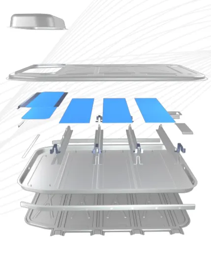
Design Benefits:
- Up to 50 percent lighter than an equivalent steel design
- Best-in-class mass-energy density at more than 160watt-hours per kilogram, an extremely efficient design for OEMs and Tier 1 battery pack manufacturers.
- Accommodates all battery cell types and is designed particularly for battery electric vehicles with larger power packs such as pick-up trucks, sport utility vehicles, and crossovers.
- Most cost-effective aluminum solution for mass production electric vehicles when compared to aluminum extrusion and casting-intense designs.
- The low price premium on $/kg saved compared to equivalent steel designs at a substantially lower weight.
As we know now
Power (p)= Voltage (v) * Current (i)
3.3 *2.5 =8.25 kw
To get 18kWh, we are assuming 44s50p
i.e; 50*44 =2200 cells
series connection gives 44*3.3 =145.2 v
parallel connection gives 50* 2.5 =125 A
from this, we can get
145.2* 125 =18.150 kWh energy or capacity.
we design battery packs for 44s and 50p cells along with battery spacers to hold cells and for their connection, a nickel strip is used
when cells are connected by a nickel strip spot welding should be used so that cells do not get damaged.
*Wiring the Components:
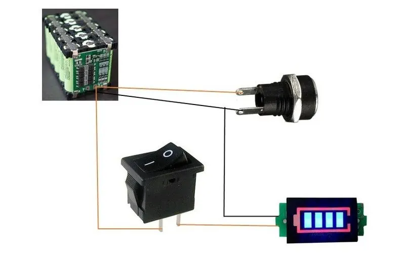
Normally a standard battery has only two terminals for connecting the load and charging the battery. Apart from this, adding a battery level indicator, to see the battery level whenever required is also possible. Using a 5mm DC jack (12V /3A ) for input/output, a 3S battery level indicator module to see the battery status, and a rocker switch to ON/OFF the battery level indicator.
Now let's move on to the wiring of the components. Preparing a simple wiring diagram for all the components. To insulate the conductive parts, using heat shrink tubing is preferable.
Note: Don't solder the wires ( P+ and P- ) to the BMS before installing the components into the enclosure.
*Final Assembly:
In this stage, we connect the BMS, assemble the packs check the sensing voltages and all connections by quality check using a multimeter. If any of the battery pack's strings and modules show irregularities in the expected voltage, resistance or capacity range, it can be found here and rectified. After wiring the semi-finished battery pack, we go for capacity testing using the individual battery capacity testing machine.
Using advanced computer software, each process will be programmed before connecting the machine with a semi-finished battery pack. Here we observe and compare the final outcome of the battery pack with what we expected from the very beginning: checking the malfunction, temperature rise in the battery pack, capacity, steady current flow, current carrying capacity of the Nickle strip, and power cable, etc. After this process, the battery pack will go for the final completion of the casing and then to the finished goods area. The following figure shows the completely finished battery module.
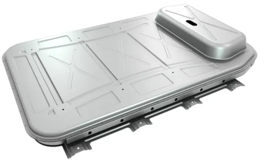
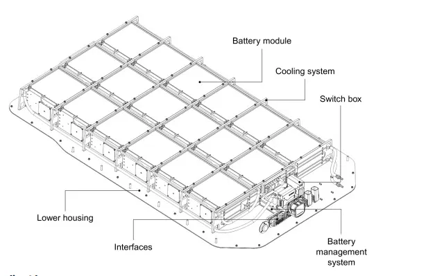
These battery modules are further used for different applications. We can connect the number of modules according to the requirement of capacity. The following figure shows the diagram of a multi-module pack, which consists of battery modules, cooling system, BMS, housing and interfaces, etc.
* Final Look:
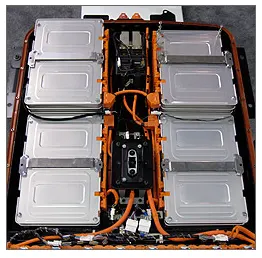
In the following figure, we can see the arrangement of modules in an Electric vehicle. This will model the battery pack and perform few tests to check all the parameters and physical characteristics of the number of cells and modules.
CONCLUSION:
For the given cell model of ANR2665031-B, we have prepared a detailed battery pack design along with its enclosure and Stated my assumptions.