Project 1 Mechanical design of battery pack
The battery pack is the heart of an electric vehicle. All the energy demands for various range and operating conditions are met by designing a suitable battery pack. In an electric car, the battery pack is stored inside a sealed compartment in the skateboard. Therefore the battery pack must be isolated from all the hazardous conditions in the outside environment since lithium ion cells are highly inflammable when in contact with oxygen. Also the battery pack must also ensure that proper heat transfer techniques are used to reduce the battery temperature during the operation.
Here for designing the 18 kWh battery pack following assumptions are made:
- The battery pack is designed for an electric car
- The overall voltage of the pack is taken as 415 V.
- The pack is designed to have a range of 350 km.
The cell given is ANR 26650 M1-B. The dimensions and configuration of the cell are taken from the datasheet.
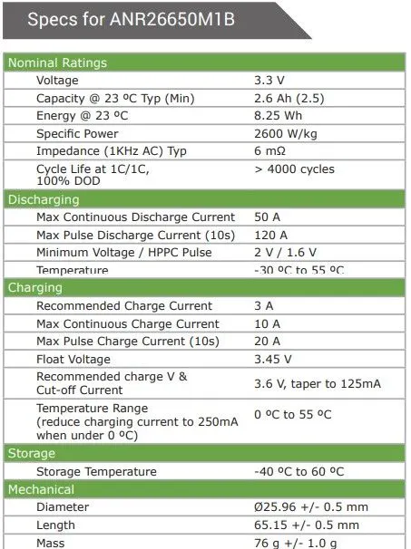
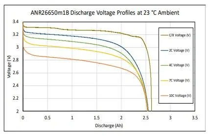
Hence from the datasheet, following information is obtained.
Nominal Voltage, `V_(bc)`= 3.3 V
Nominal cell capacity , `C_(bc)`= 2.5 Ah
Battery cell energy, `E_(bc)`= 8.25 Wh
Length of the cell , l = 0.065 m
Diameter of the cell , d = 0.026 m
Mass of the cell, `m_(bc)` = 0.076 kg
Range of the car, `D_v`= 350 km
Battery pack voltage, `V_(bp)=415__V`
From the above dataset, the volume of the cell can be calulated as: Volume = `pi/4*d^2*l`
= `pi/4times0.026^2times0.065`
= `3.45times10^-5 m^3`
Also Battery cell energy can be also given as, `E_(bc)=C_(bc)*V_(bc) = 2.5times 3.3 = 8.25 __ Wh`
Volumetric Energy density,`U_v=E_(bc)/(Volume)= 8.25/(3.45times10^-5)= 239.13times10^3W//m^3= 239.13__W//l`
Gravimetric energy density,`U_g= E_(bc)/m_(bc)= 8.25/0.076 =108.55 __ W//kg`
The number of cells in series and parallel connection required to meet the conditions is to be calculated
Number of cells in series, `N_(cs)= V_(bp)/V_(bc)= 415/3.3 = 125.75 approx126`
Energy content of string, `E_(bs)= N_(cs)*E_(bc)= 126times 8.25 = 1039.5__ Wh`
Therefore, total number of strings (parallel connection) , `N_(sb)=E_(bp)/E_(bs)= (18times10^3)/1039.5=17.31 approx 18`
The battery pack total energy(recalculated), `E_(bp)= N_(sb)*E_(bs)= 18 times1039.5 = 18711 __Wh =18.711__ kWh`
The battery pack total voltage(recalculated),
Battery pack capacity, `C_(bp)=N_(sb)*C_(bc)= 18times2.5=45 __Ah`
therefore, total number of cells, `N_(cb)=N_(sb)*N_(cs)= 126times18=2268`
Battery pack mass (cell only) , `m_(bp)= N_(cb)*m_(bc)= 2268times0.076=172.368 __kg`
Battery pack volume (cell only),`v_(bp)=N_(bc)*v_(bc)=2268times3.45times10^-5=0.078246__m^3`
Now since the number of cells in series and parallel is calculated, the battery pack can be modelled.
In electric vehicles, the battery is stored as modules, where a module contain a pre defined number of cells. This division is done inorder to divide the total high voltage into smaller voltage range. This division is done taking into consideration as a continuous single loop may then contain voltage value as high as above 400 V.
Hence the battery modules are individually breaken down to smaller voltage values and are connected together in series to add upto the desired pack voltage.
For the assumption taken above the configuration need is 126s18p containing 2268 cells. For modelling these are then divided into modules of 18s18p and are connected in series through a 7 module setup, thereby adding upto the 126s18p arrangement.
The cells are arranged and setup using a battery holder. The battery holder holds together the bunch of cells which are then carefully placed inside the module.
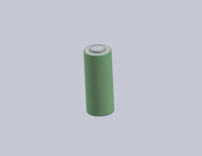 |
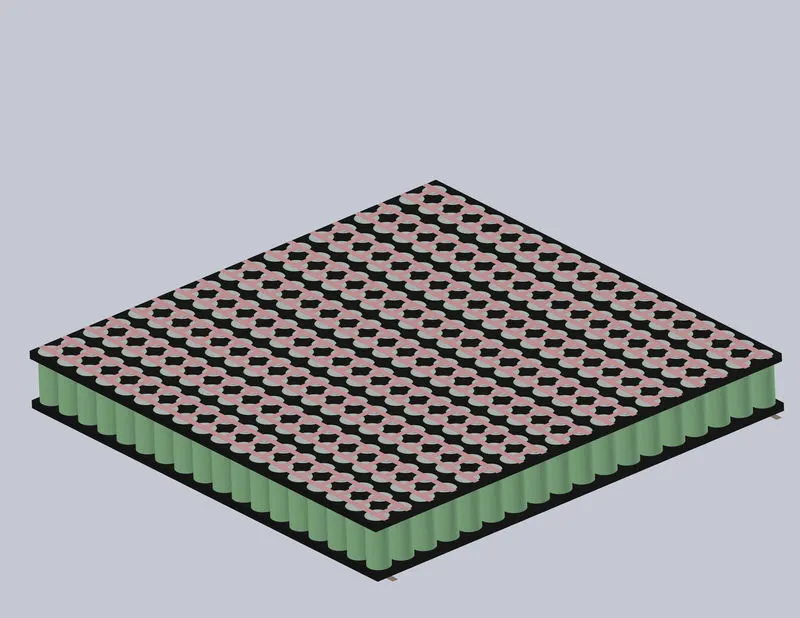 |
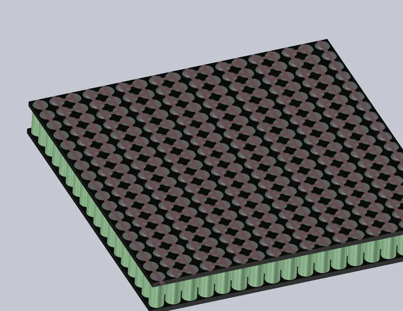 |
| Cell modelled in solidworks | Cell arrangement in battery holder (Side A) | Cell arrangement in battery holder (Side B) |
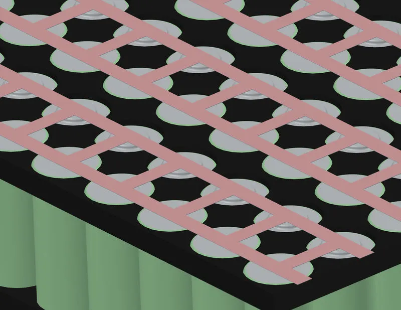
A closer look to the cell arrangement on both the sides is shown below:
 |
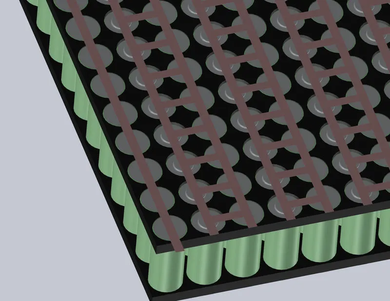 |
| Side A | Side B |
The positive and negative terminal for the whole module is obtained from the Side B, where the nickel strips at each end of the arrangement position to give the voltage and current measurements of the single module.
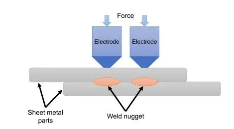
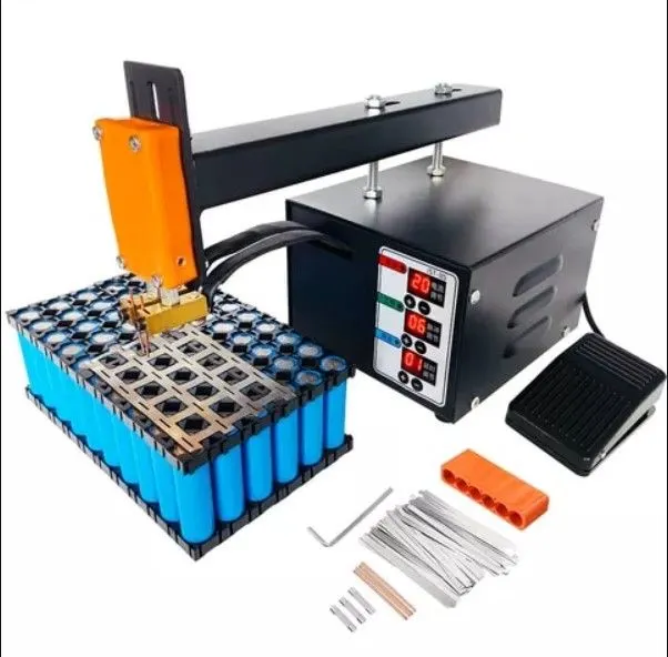
Here nickel strips are used to obtain the 18s18p connection setup. Typically the nickel strips are welded onto the cell terminal by using spot welding technique.
|
|
|
|
Resistance Spot Welding is a technique where two or more metal sheets are welded together through the application of an electrical current and pressure between two electrodes. The electrical resistance of the material at the interface results in the generation of heat and melts the materials together without the use of filler material or gases. |
|
|
|
|
|
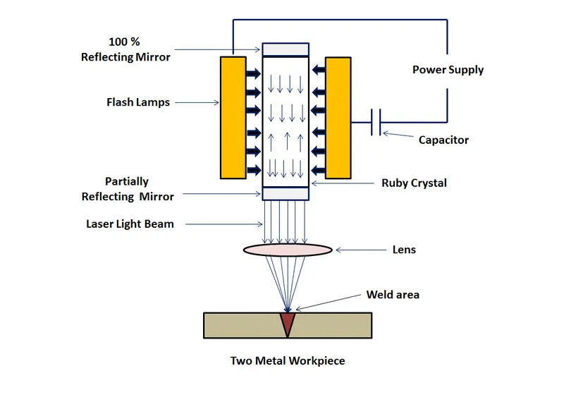
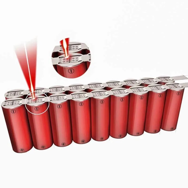
Laser beam welding or LBW is a welding technique in which a laser beam provides a concentrated heat source that fuses the materials together. A lasing medium, a lasing cavity, and a pumping source are all primary components in a laser welding machine as shown in the figure. |
|
|
Weld pattern for nickel strips in lithium ion cylindrical cells |
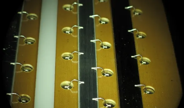
In some tesla and race cars, instead of nickel strips, plates are used. Here the connection is achieved by using a technique called wire bounding. Wire bonding is a ultrasonic metal-metal friction welding process |

The welded cells held together are then placed in a cell module. The cell module encases these battery pack and provides the mechanical support for the cells as shown in the figure below:
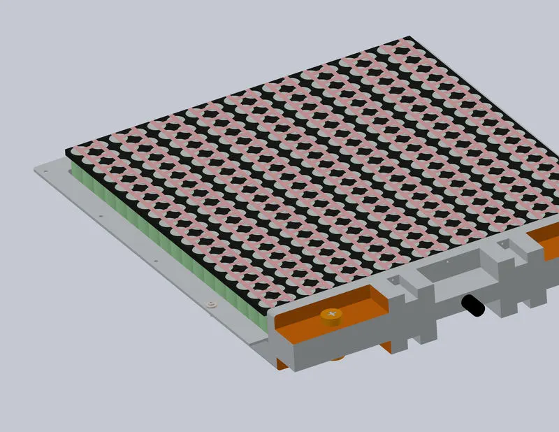 |
In the figure shown, the module casing is made of a thermally conductive material. This is done to conduct the heat generated to the cooling pad found beneath the module assembly. The cap of the module casing has orange markings for high voltage bath. One of the terminal pairs of them gets connected to the heat voltage bus bar current conduction and the other pair of wires are then connected to the Battery Managemeny System (BMS) Inside the cap of the module, there will be a slave battery management system, that collects and monitors cell data as well as communicate with the master BMS. The orange colour is denoted for high voltage and the black one for low voltage. |
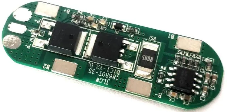 |
A typical slave BMS or Battery Protection Module is attached to each battery module to have a better control on module level. Using a slave BMS can also improve the performance of the master BMS. The various ports of the BMS connected as detailed below: P1: Negative Terminal Connection for the battery pack P2: Positive Terminal Connection for the battery pack T : For attaching the temperature sensor B+ : Positive terminal of the first battery B- : Negative terminal of the last battery B1 : Connection to 1st battery B2 : Connect with the 2nd battery |
Of the various cooling techniques used, liquid cooling is the most commonly employed battery pack cooling in electric vehicles. In liquid cooling, many methods are used.
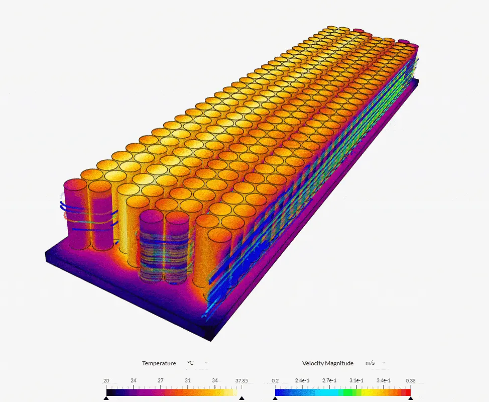 |
Many models like the Tesla S battery pack allow fluid to flow through a flow channel that is incorporated between each row of battery pack. This type of cooling is much effective when a large number of cells are needed to be cooled. |
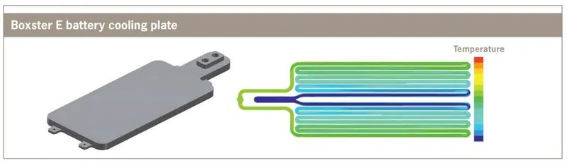 |
For much smaller battery packs, a cooling plate technique is commonly used. Here the heat is transferred by conduction to a cooling plate that carry cooling fluid, which in turn cools the battery pack by convection. |
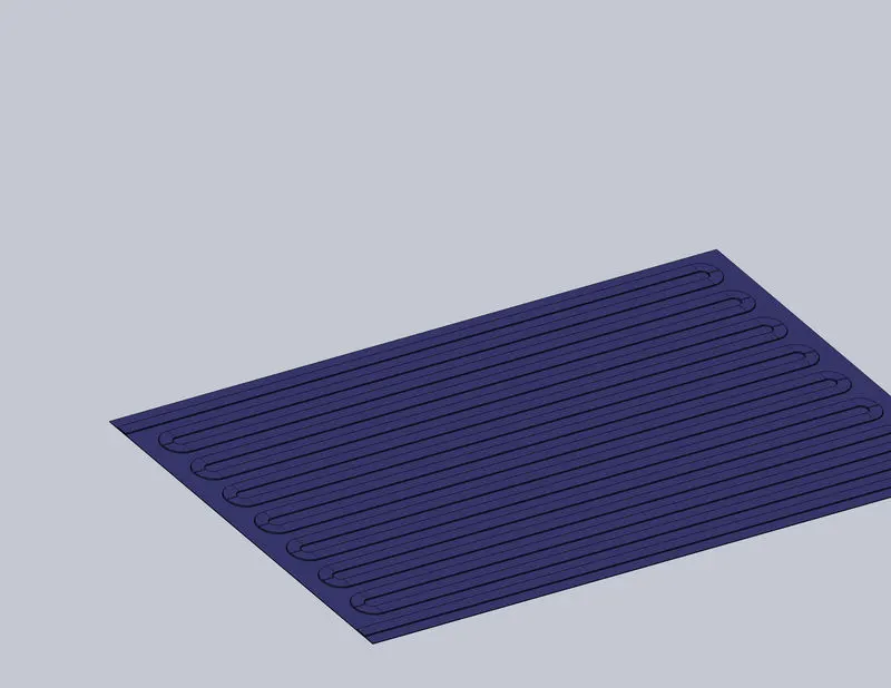
So, for cooling a total of 2268 cells, the cooling plate method is chosen. The cooling plate is modelled as shown below
 |
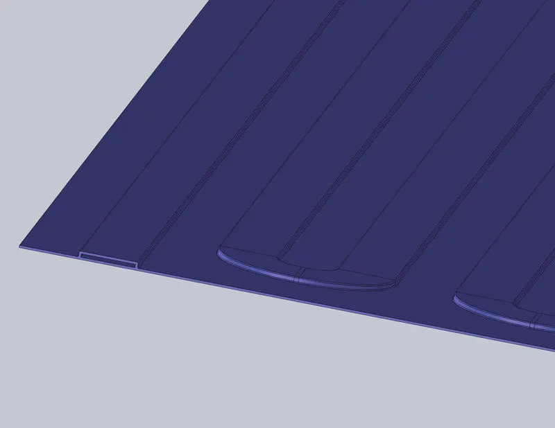 |
| Cooling plate | Flow channels in cooling plate |
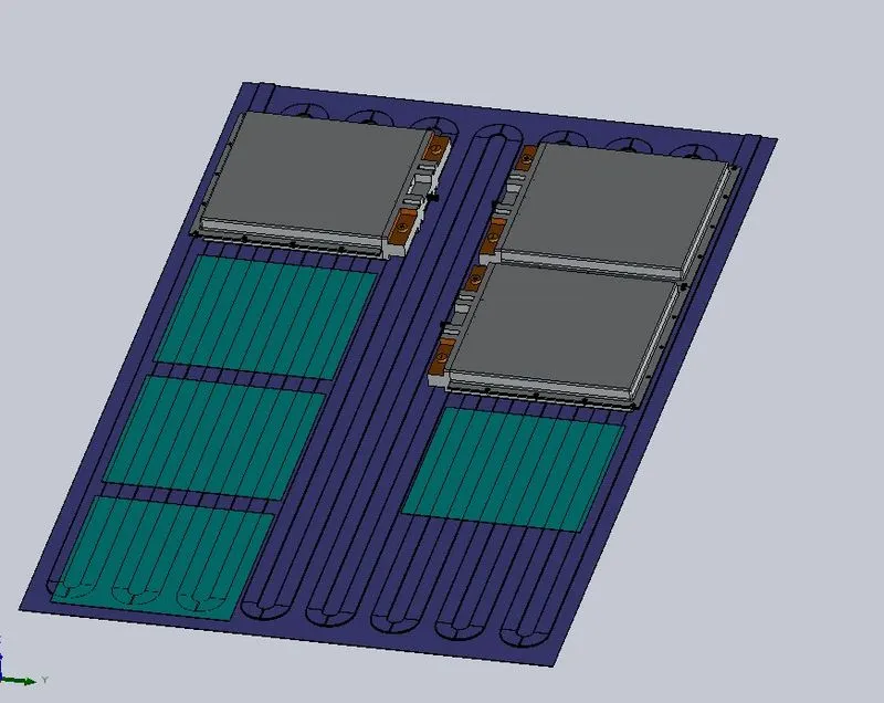 |
For the model shown in figure, the blue pads are the heat conducting pads are represented as aqua-green coloured sheets. These sheets helps in conducting the heat from the surface of battery modules to the cooling flow fluids below. An insulating pad is also provided in the underside of the cooling plate so that external atmospheric conditions don not interfere the heat transfer. |
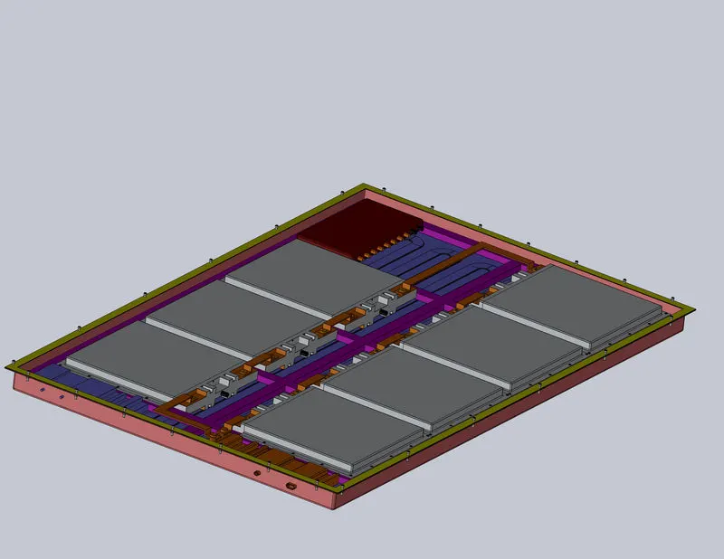 |
Since each module is of 18S18P connection setup, 7 modules are hence connected in series as shown in the figure. Thus each cell module voltage will be equal to `N_(cs_(mod.))*V_(bc)= 18times3.3=59.4__V` |
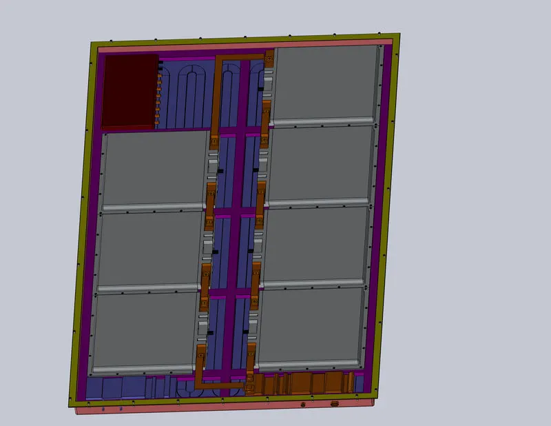 |
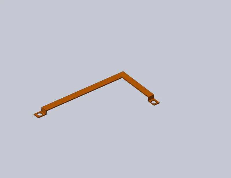
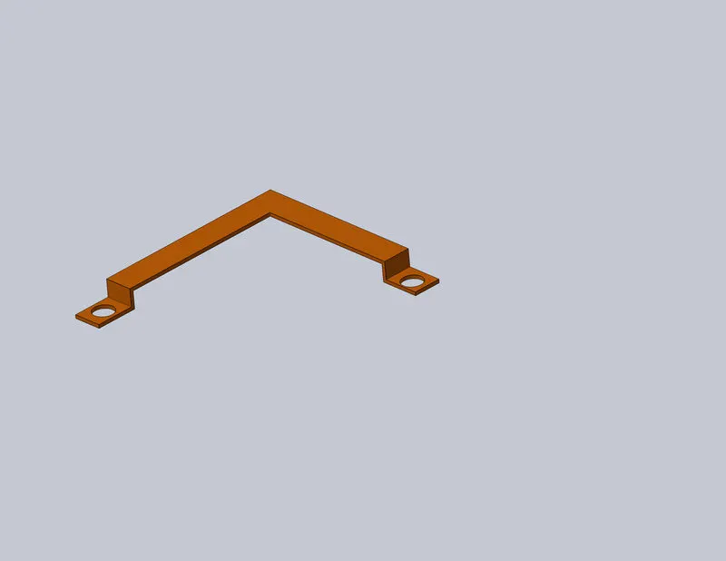
Inorder to achieve the total voltage capacity each cell module is connected in series from the high voltage contactor. Inorder to connect them in series, bus bars are used |
| Busbars are solid metal bars used to carry current. Typically made from copper or aluminum, busbars are rigid and flat wider than cables but up to 70 percent shorter in height. They can also carry more current than cables with the same cross-sectional area. These attributes make busbars ideal for some high-voltage connections in electric vehicles (EVs) . | 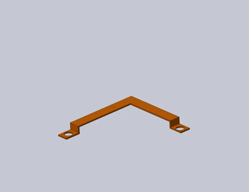 |
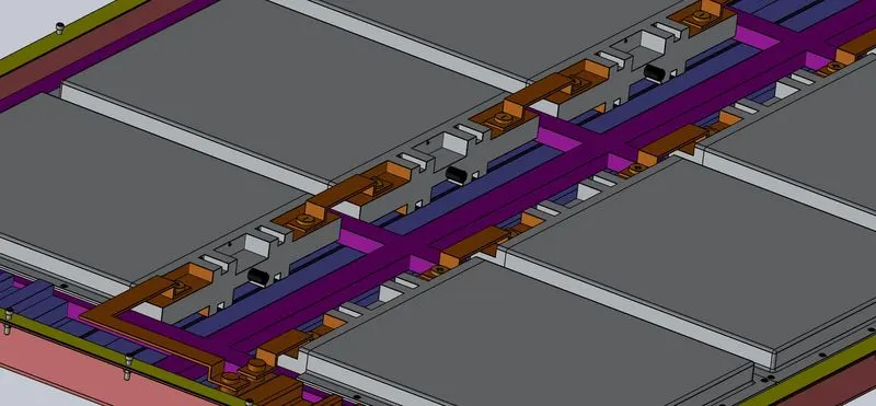 |
Bus bars are connected in series from the positive terminal of one module to the negative terminal of the other module. |
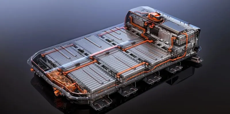 |
The high voltage wires are given orange colour while the low voltage wires are given black colour. This is an industrial standard used to easily identify the systems that carry high voltage so technicians can excercise caution while working on such systems. |
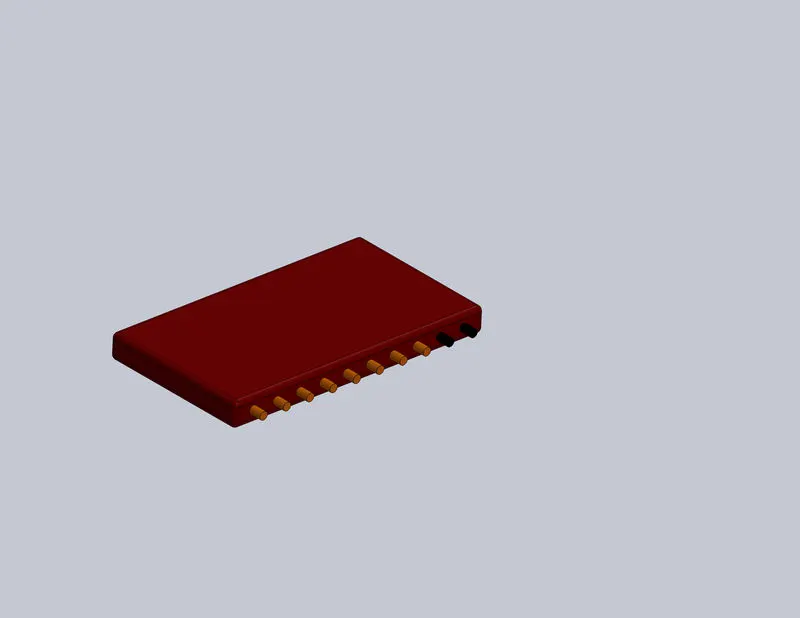 |
The Master BMS recieves all the signals from the slave BMS and balances the cell. Also the Master BMS monitors the temperature along with the voltage for safe operation of the battery pack |
| The coolant distribution system recieves the coolant from the coolant pump and then distributes the fluid through the coolant channel and recieves the hot fluid which is cooled and then recirculated into the system. | 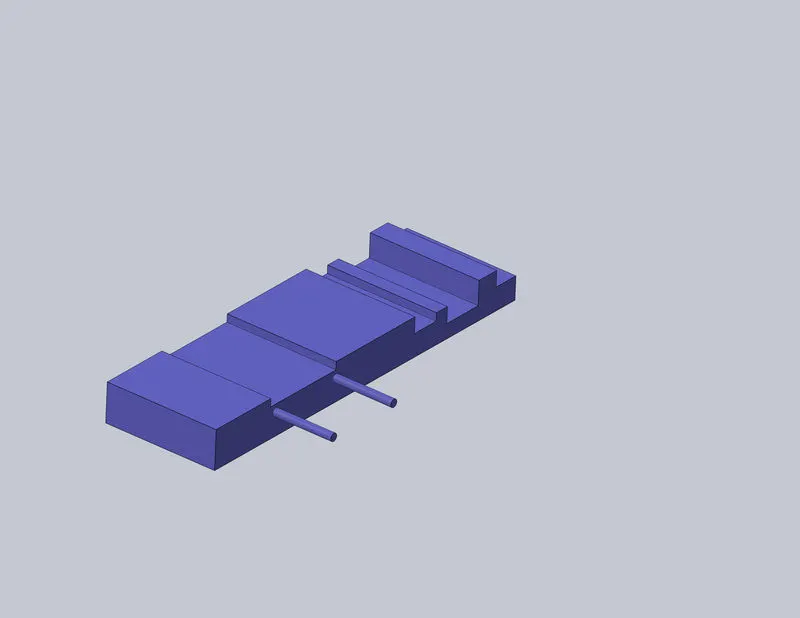 |
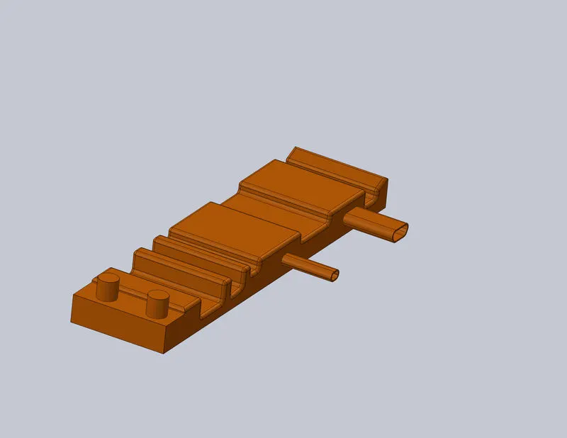 |
The high voltage relay assembly contains the contactors for supplying the high voltage current in and out of the system. It has negative and positive contactor for the entire pack along with the pre charge and charge contactor. |
 |
The complete assembled view is as shown in the figure. The green coloured sheet is the top cover and the copper colour sheet below is the bottom cover. The entire assembly goes into the battery skateboard. |
| The yellow coloured narrow component on the edges of the bottom cover is the sealing gasket that seals the battery pack from external environment. | 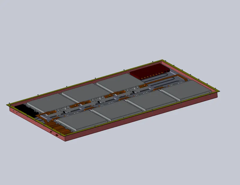 |
| NAME | IMAGE | QUANTITY | DIMENSION (MAX.) in mm |
| Top Cover |  |
1 | 2724 X 1728 X 10 |
| Bottom Cover | 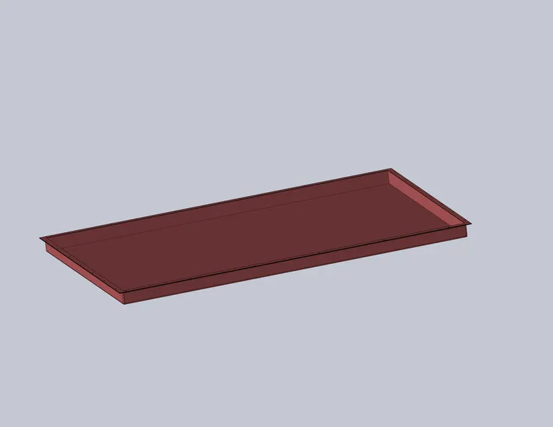 |
1 | 2726 X 1730 X 105 |
| Gasket |  |
1 | 2724 X 1728 X 5 |
| Frame | 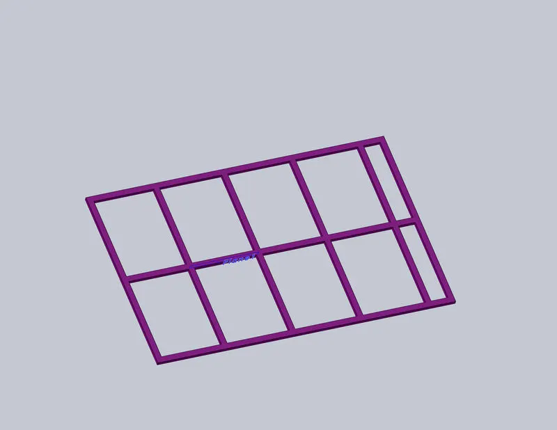 |
1 | 2646 X 1650 X 30 |
| Battery Module | 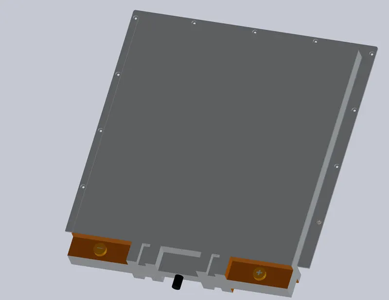 |
7 | 585 X 660 X 86.5 |
| Cooling plate | |
1 | 2646 X 1650 X 7 |
| Heat conducting pad |  |
7 | 555 X 534 X 2 |
| Insulating Pad |  |
1 | 2646 X 1650 X 4 |
| Bus bar | 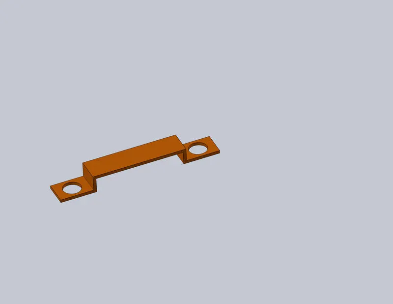 |
6 | 265 X 40 X 27 |
 |
1 | 654.5 X 322.5 X 27 | |
 |
1 | 332 X 287.5 X 27 | |
| Battery Management System | |
1 | 534 X 300 X 50 |
| Coolant distributor | |
1 | 500 X 150 X 50 |
| High voltage relay assembly | |
1 | 600 X 150 X 50 |
| Battery holder | 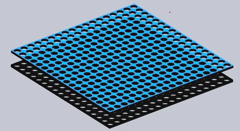 |
7 | 540 X 540 X 65.15 |
| Nickel strip | 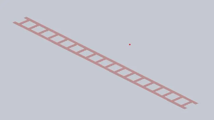 |
126 | 540 X 37 X 0.15 |
| ANR 26650 M1-B lithium cell | |
2268 | `phi26times 65` |
| The exploded view of the components that make up the battery pack | 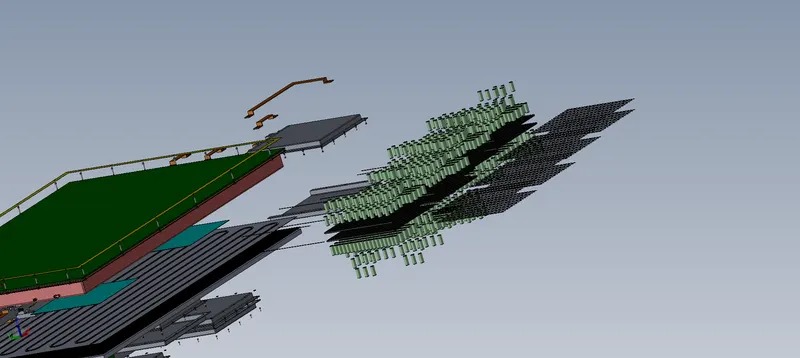 |
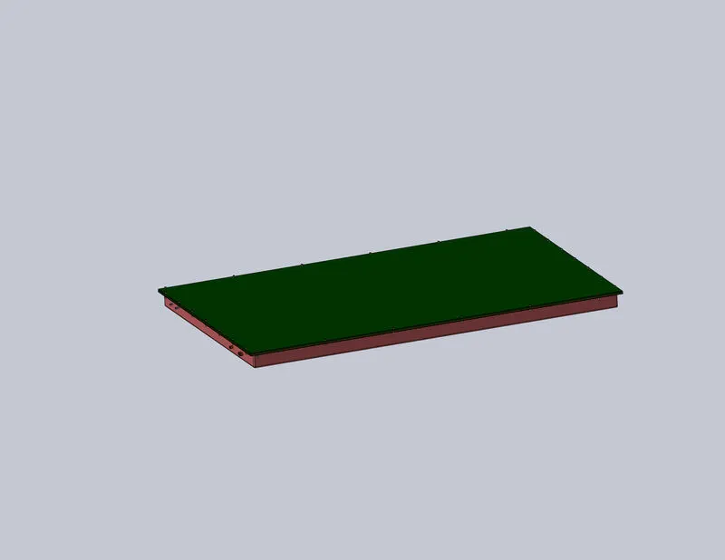 |
The overall dimension (maximum ) of the battery pack designed is 2726 X 1730 X 120 mm |
| The battery pack goes into the skateboard of a car as shown in the figure | 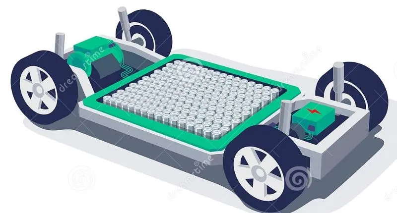 |
Note: The solidworks model is attached.
REFERENCE
- https://x-engineer.org/ev-design-battery-calculation/
- https://circuitdigest.com/article/tesla-model-s-battery-system-an-engineers-perspective
- https://circuitdigest.com/electronic-circuits/designing-12v-li-ion-battery-pack-with-protection-circuit
- https://www.qats.com/cms/2018/10/12/industry-developments-in-thermal-management-of-electric-vehicle-batteries/
- https://www.youtube.com/watch?v=ssU2mjiNi_Q&ab_channel=WeberAuto