Project 1 Mechanical design of battery pack
PROJECT 1
MECHANICAL DESIGN OF A BATTERY PACK
AIM:-
To design a battery pack with a capacity of 18kWh and Cells ANR26650M1-B and also to prepare a detailed battery pack drawing along with the enclosures.
Project Description:-
ANR26650M1-B cell specifications and applications:-
A123’s high-performance Nanophosphate lithium iron phosphate (LiFePO4) battery technology delivers high power and energy density combined with excellent safety performance and extensive life cycling in a lighter weight, more compact package. Our cells have low capacity loss and impedance growth over time as well as high usable energy over a wide state of charge (SOC) range, allowing our systems to meet end-of-life power and energy
requirements with minimal pack oversizing.

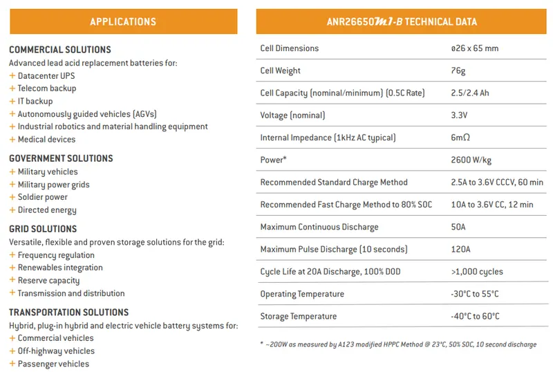
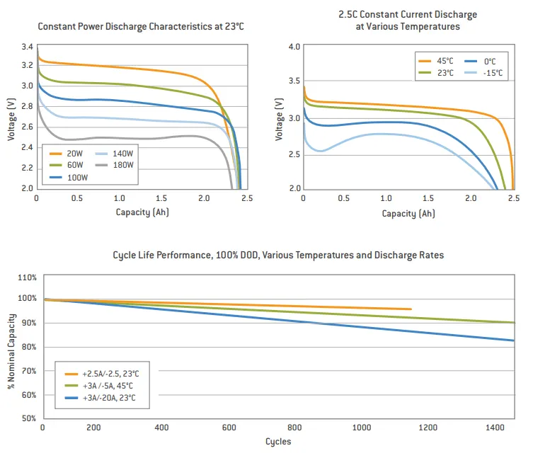
The indiviual cell specification of a ANR26650M1-B cell with its data sheet, current characteristics, discharge characteristics and its cycle life performance under various nominal capacities and the temperatures are detailedly given as above.
Cylindrical Cell Primary Applications:
- Portable high power devices
- Stationary battery backup systems
- Grid stabilization energy storage systems
- Commercial truck and bus hybrid electric vehicles (HEVs)
Battery Pack:-
A battery pack is a device that stores electrical energy to provide power to an electrical system, such as an electric vehicle (EV) or an energy storage system (ESS). The energy is stored in cells that are all connected to one another in the battery pack.
To provide sufficient power, battery packs require a minimum voltage level which a single cell cannot achieve. Multiple cells are therefore connected in series to boost voltage. Some designs use small-capacity cells. To achieve the desired battery energy, cells are connected in parallel to boost capacity. Cells connected in parallel provide power as if they were a single, larger cell.
Battery packs are made of multiple, smaller sections called battery modules (or sub packs). These modules include a smaller number of cells connected in series and parallel. They are usually at a lower voltage, which is safe for handling. Modules facilitate servicing when only a few cells are defective and if they can be replaced without replacing the entire battery. EV batteries are typically made of 4 to 40 modules connected in series to one another.
Components of a Battery pack:-
A battery pack is the most expensive part in an electric vehicle. It is a complex system made of a wide range of components. Here are some of the important components.
- Cells are the most important components of a battery pack. The mixture of materials comprising the cell is known as its chemistry. Different battery chemistries can achieve different performances and specifications. There are two common types of cells: energy cells and power cells. There are also many variants to provide the perfect trade-off depending on the application. In the EV industry, the lithium-ion cell (li-ion cell) is the most common chemistry. Alternative chemistries are sometimes used, such as Nickel-Metal Hydride (NiMH), which offers a slightly better lifecycle.
- Electrical connectors such as busbars, wires, or other distribution conductors are used to make series or parallel connections between cells and groups of cells. These connections are typically done using ultrasonic bonding or laser welding. Busbar connections between modules can also be done mechanically using fasteners.
- Thermal interface materials (TIMs) such as pastes, adhesives and gap fillers are inserted between battery components to join them mechanically while improving thermal properties between surfaces. With the rise of the structural battery pack, TIMs are becoming essential components.
- The Battery Management System (BMS) protects cells by monitoring key parameters such as voltages, currents, and temperatures. It is responsible for cell balancing (to maintain the optimal performance of the cells at the right voltage) and communicates with several systems such as engine management and temperature control. It also includes protection devices that can shut down the battery if needed.
- The Battery Thermal Management System (BTMS) controls the thermal energy in the electric vehicle’s powertrain and cabin, providing cooling or heating as needed to meet the battery’s thermal needs and protect the cells. The BTMS includes several components such as a heat exchanger, tubes, hoses, cold plates, pumps, valves, and temperature sensors.
- The Contactor System is a switch controlled by the battery management system. It can cut off the electrical connection between the main battery and the high voltage bus, which delivers current to the traction motor and other high-voltage components.
- The Housing is a rigid enclosure that protects the battery from environmental factors such as water, dust, and salt. It helps maintain a precise temperature and electrical insulation in the battery, and it prevents damages like rust and slow shorts.
- The Communications System ensures communication with other components in the electric vehicle. The most used protocol is CAN bus.
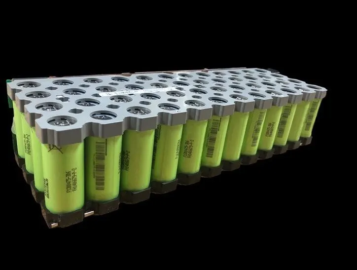
Finally when all the essentiall components are arranged and packed, the battery pack will look like as follows:-
Different types of interfaces, used for a battery pack design are gives as:-

MANUFACTURING TECHNIQUES OF A BATTERY PACK:-
STEP ONE: LEARN HOW TO CONNECT THE BATTERY CELLS
You need to connect your battery cells together, and that’s where your nickel strips come in.
FYI, pure nickel strips are better than the nickel-plated ones, as the Instructables tutorial states, and that’s because it contains lower resistance.
This is important to ensure your battery pack will generate less heat during charging cycles, which makes it safer to use and will prolong its lifespan.
An important note when joining the cells together: check all of the cells’ voltages.
Because you’ll be connecting them in parallel, the cells’ voltages need to be the same so that a high current from one cell won’t enter a cell with lower voltage and damage it.
STEP TWO: ASSEMBLE YOUR BATTERY PACK
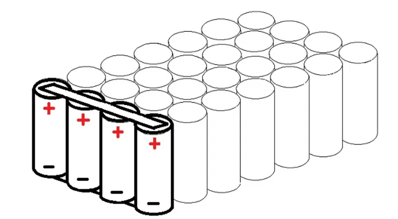
Now, your pack needs to consist of three groups of cells and each group needs to have five cells in it.
So, go on and arrange your 15 cells so that you can produce the electrical connection in them with the BMS board.
You should put the first group of five cells positive side up, then the second one negative side up, and the last one positive side up.
STEP THREE: CUT YOUR NICKEL STRIPS
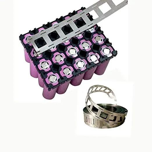
Take your pure nickel strip and put it on top of five cells. It needs to cover all the cell’s terminals and ensure you have about 10mm excess to connect them to the BMS.
Then, connect the first group’s negative terminal to the positive terminal of the second, and finally the negative terminal of the second to the positive of the third.
STEP FOUR: SPOT-WELD THE STRIPS
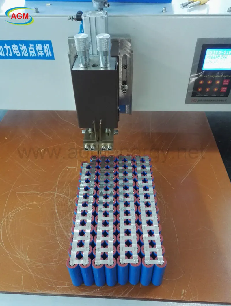
Now you need to spot-weld your pure nickel strips. The welder needs to be pushed against the nickel strip and battery terminal before you press the foot switch.
Not sure if you’ve welded it correctly?
Try to pull the nickel strip. If it comes off easily, then it needs to be welded again but try using a stronger current.
When spot welding, always wear your safety goggles and protective gloves because spot welders create a lot of heat and you don’t want to get injured.
STEP FIVE: CONNECT YOUR BMS
Your BMS is important because it monitors the cells to ensure that they have the correct voltage and it also monitors the charging and discharging of the battery pack.
If you want to ensure your BMS is fit for this battery pack’s specifications, then you must ensure that it has the following criteria: It should have a voltage range of 4.25~4.35 volts ±0.05 volts. It should have a maximum operating current of 0~25A.
To connect your BMS to your battery pack, you should note the BMS’s soldering pads- B-, B1, B2, and B+.
Connect your first parallel group of cells’ negative terminal to the B- and the positive terminal to the B1.
Then, the next group needs to have its negative terminal connected to the B2 and positive terminal the B+.
To keep them together, simply spot weld the BMS to the nickel strips.
STEP SIX: CONNECT THE WIRING
You will need to connect the wiring of your battery pack so that there are two terminals: one for connecting the load and the other for charging the battery.
However, if you want, you can also connect the battery level indicator. This is a nice touch to your finished product.
The detailed contruction of a sample battery pack video is given below:-
Mathematical calculations to design a battery pack:-
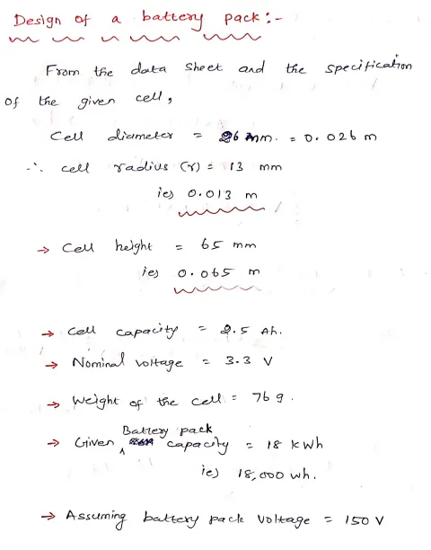
Dimensions of a single cell:-
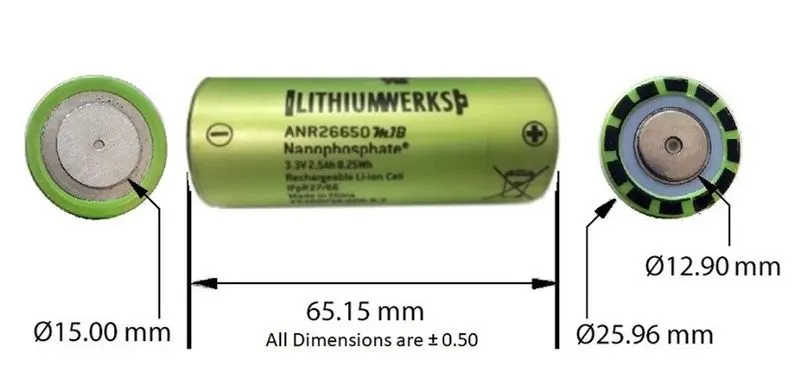
GIVEN DATAS:-
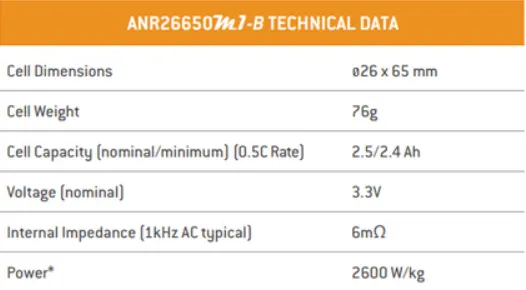
CALCULATIONS:-




RESULT:-
Hence a sample battery pack is designed for the given 18kwh energy.
References:-