Project 1 Mechanical design of battery pack
AIM:- The aim of the project is to prepare a detailed mechanical design of the battery pack made by combination of cell of ANR26650M1-B
PROCEDURE :-
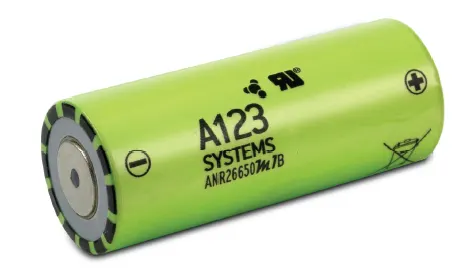
The cell used for this purpose is ANR26650M1-B which is a high-performance Nanophosphate®lithium iron phosphate (LiFePO4) battery technology delivers high power and energy density combined with excellent safety performance and extensive life cycling in a lighter weight, more compact package. Our cells have low capacity loss and impedance growth over time as well as high usable energy over a wide state of charge (SOC) range, allowing our systems to meet end-of-life power and energy requirements with minimal pack oversizing.
APPLICATIONS:-
- COMMERCIAL SOLUTIONS
Advanced lead acid replacement batteries for:
+ Datacenter UPS
+ Telecom backup
+ IT backup
+ Autonomously guided vehicles (AGVs)
+ Industrial robotics and material handling equipment - GOVERNMENT SOLUTIONS
+ Military vehicles
+ Military power grids
+ Soldier power
+ Directed energy - GRID SOLUTIONS
+ Frequency regulation
+ Renewables integration
+ Reserve capacity
+ Transmission and distribution - TRANSPORTATION SOLUTIONS
Hybrid, plug-in hybrid and electric vehicle battery systems for:
+ Commercial vehicles
+ Off-highway vehicles
+ Passenger vehicles
TECHNICAL SPECIFICATION OF THE CELL
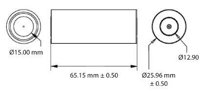
| Cell Dimensions | Ø26 x 65 mm |
| Cell Weight | 76g |
| Cell Capacity (nominal/minimum) (0.5C Rate) | 2.5/2.4 Ah |
| Voltage (nominal) | 3.3V |
| Internal Impedance (1kHz AC typical) | 6m |
| Power* | 2600 W/kg |
| Recommended Standard Charge Method | 2.5A to 3.6V CCCV, 60 min |
| Recommended Fast Charge Method to 80% SOC | 10A to 3.6V CC, 12 min |
| Maximum Continuous Discharge | 50A |
| Maximum Pulse Discharge (10 seconds) | 120A |
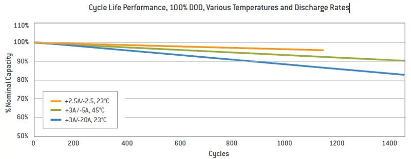
| Cycle Life at 20A Discharge, 100% DOD | >1,000 cycles |
| Operating Temperature | -30°C to 55°C |
| Storage Temperature | -40°C to 60°C |
PERFORMANCE OF THE CELL
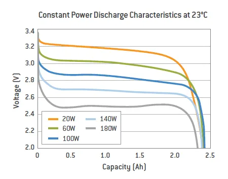
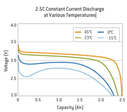
Cell resistance changes with cell temperature. The warmer the ambient and/or cell temperature, the lower the resistance. Note that in Figure 5, the cells hold up voltages at cold temperatures less effectively than at ambient room temperatures. Voltages reach parity when the cells heat up to or beyond ambient room temperatures.
- Constant Power Discharge Characteristics at 23°C
- 2.5C Constant Current Discharge at Various Temperatures
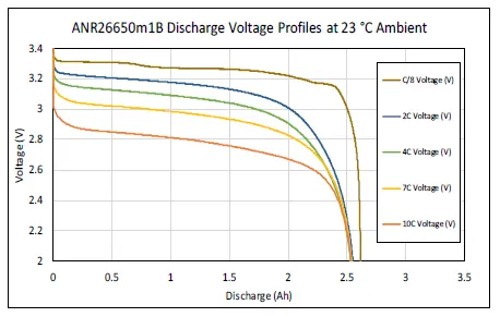
- Discharge Voltage Profiles at 23 °C Ambient
Cycle Life Performance, 100% DOD, Various Temperatures and Discharge Rates
Basic Pack Design
Overview
Battery Packs (also known as Energy Storage Systems (ESS) and battery modules) should be designed to protect and replicate the individual cell performance of multiple cells in the pack. This means providing mechanical protection and integrity, thermal stability, and electrical protection and performance.
Mechanical Connection and Protection
Design mechanical interconnects to prevent accidental short circuits. Size these mechanical interconnects to carry the expected maximum rated current for both the maximum time and ambient temperature in which the pack is expected to operate.
DIMENSIONS OF THE CELL
Cell Interconnects
Size cell interconnects for the expected maximum current carrying capability. Improperly sized tabs could heat up excessively, resulting in even higher resistivity. For reliable welded connections at the terminals, A123 Systems recommends either pure nickel tabs or nickel-clad copper tabs. In addition, other alloys afford both the weldability, strength and low resistance, which are all desirable features of a good interconnection. Cell interconnects (tabs) should be neither soldered on the end caps nor attached using extreme heat. A123 Systems recommends tabs be resistance or laser-welded to both ends of the cells. Resistance welding provides a constant current for a specified period of time through a salient feature in the weld tab. These parameters can be specified and regulated for a consistent high-quality weld every time.
Allowing the Cell to Vent in a Fault Condition
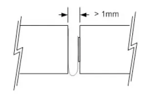
The cell vents, located on the end cap(s) of the cells (on the POSITIVE side of the cell), should not be blocked by any mechanical means. Blocking the cell vent and then sufficiently abusing the cell so as to build up pressure in the cell prevents the cell from properly venting. An ESS designed to install cells end-to-end needs at least 1 mm of space between the cells to allow the vent to open under fault conditions.
Cell Insulation
The outside case of the 26650 and 32113 is electrically connected to the positive end (cathode) of the cell. Take care to keep this surface electrically-isolated from any electrical bus bar or mechanical support that may be of different voltage potential. Insulation, such as tapes, shrink wraps, or sleeves, must have at least a 150 °C melting point. This helps ensure that the cells do not short circuit to each other in a high temperature fault condition, which could cause even more widespread damage.
Cell Support
Secure the cells in place by supporting their outside cases, not their terminal ends. The vibration induced between the terminal ends and the rest of the case has been shown to be detrimental to the life of the cell, causing internal and external cell damage. The intercell terminations must be light enough not to cause vibration-induced damage to the cell.
Cell Protection
In addition to being supported, protect cells from exposure to corrosive substances and oxidizing catalysts, such as dust and moisture. The necessary level of protection for cells in a battery pack varies depending on the intended application. For example, a battery pack designed for use in an HEV must have an enclosure that isolates cells from shock and vibration, protects them from dirt and debris, as well as shielding them from other environmental dangers, such as salt spray. Unless it is hermetically sealed, even a sealed enclosure is subject to pressure differentials between its insides and the ambient, causing minute amounts of air exchange. Therefore, over time, some moisture may accumulate and condense on inside surfaces. An ESS designed to be sealed from the environment (from dust, moisture, and VOCs) must have a way to benignly drain off whatever condensate does manage to leak into it. In addition, enclosures protecting cells must work with the thermal management system to achieve optimum durability and safety of the battery pack. For example, a poor choice of materials for the enclosure, combined with insufficient cooling and controls, may cause the battery pack to overheat.
Thermal Management
A123 Systems’ cells operate throughout a wide temperature range; however, they are most effective between 10°C and 50°C. The temperature differential between the coolest cells and the hottest cells should be no more than 10°C. Careful attention to thermal management is necessary to keep the cells operating at peak efficiency and avoiding fault conditions. In most cases, this implies a cooling system. There are certain applications - such as HEV vehicles operating in cold climates - where a heater is beneficial to keeping the cells operating in their optimal range.
Electrical
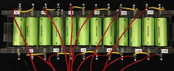
When joining cells together, A123 recommends using a Battery Management System responsible for carefully monitoring cell voltage, current, and impedance. The BMS may be implemented as discrete circuitry or through a microcontroller.
Cell Monitoring
To ensure optimal performance, safety, and durability of the pack, the Battery Management System must monitor the voltage of each individual series cell in a battery string.Take care to place the voltage monitoring connections in such a place that they are not affected by high currents going through the interconnection elements
Now for calculating our required battery pack based on the cell manufacture data provided.
The calculation for the battery pack is as follows.
1. Volume of each cell
Cylindrical volume`V c [ m^3 ]`
`V C c = π D 2 b c/ 4 ⋅ L b c`
From the datasheet we have
Dbc=26mm=0.026m">`D_(b c) = 26 m m = 0.026 m` & `L _(b c) = 65 m m = 0.065 m`
Dbc=26mm=0.026m">`∴ V _(C c) = π ⋅ 0.0 25 0.2 ⋅ 0.065/4 = 3.5 × 10^(−5) m^3`
Dbc=26mm=0.026m">The volume of each cell is 35mm^3
2. Battery Cell Energy
Ebc=2.5×3.3=8.25Wh">Ebc=Cbc * Ubc
we have,
Cbc=2.5Ah">Cbc=2.5Ah
Ubc=3.3V">Ubc=3.3V
Substituting the values in above equation we get
Ebc=2.5×3.3=8.25Wh">Ebc=2.5×3.3=8.25Wh
3. Battery cell energy density
- Volumetric energy density
`u G = E b c /V cc`
Substituting the value
`8.25 /3.5 × 10^(−5)`= `235714.3 (Wh)/m^3`
- Gravimetric energy density
`u_G = E_(bc)/m_(bc)`
Substituting the above calculated values in the equation, we get,
`8.25/0.076=108.55(Wh)/(kg)`
4. Total number of the battery pack
The total energy of the battery pack which is required is given as 18 kWh
`E _(b p) = 18000 W h`
5. Number of cells connected in series
It is calculated by dividing the nominal battery pack voltage Ubp [V] by the voltage of each battery cell Ubc [V]. The number of strings must be an integer. Therefore, the result of the calculation is rounded to the higher integer.
`N_ (b c) = U_ (b p)/ U _(b c)`
Let us assume that the battery pack voltage which is required to be 330V and the nominal voltage of the battery as per the datasheet is given as 3.3V.
`330 /3.3 = 100`
The total number of cells in series is 100
6. Energy Content of a string
The product between the number of battery cells connected in series and the energy of a battery cell
`E_( b s) = N _(c s) ⋅ E _(b c) = 100 × 8.25 = 825 W h`
7. Number of strings in the battery pack
It is calculated by dividing the battery pack's total energy Ebp [Wh] by the energy content of a string Ebs [Wh]. The number of strings must be an integer. Therefore, the result of the calculation is rounded to the higher integer.
`N _(s b) = E_( b p)/ E _(b s) = 18000 /825 = 21.81`
All the 22 strings will be connected in parallel
8. Battery pack Capacity
It is calculated as the product between the number of strings Nsb [-] and the capacity of the battery cell Cbc [Ah].
`C_( b p) = N _(s b) . C _(c b) = 22 ∗ 2.5 = 55 A h`
9. Total number of cells of the battery pack
It is calculated as the product between the number of strings Nsb [-] and the number of cells in a string Ncs [-].
`N _(c b) = N _(s b) ⋅ N _(c s) = 22 ∗ 100 = 2200`
The total number of cells required for the design pack is 2200.
10. Mass of the battery pack
It is the product of the total number of cells Ncb [-] and the mass of each battery cell mbc [kg].
`m_(bp) = N_(cb)*m_(bc) = 2200 ** 0.076 = 167.2 Kg`
`V _(b p) = N_( c b) . V _(C c) = 2200 ∗ 3.5 ∗ 10^ (− 5) = 0.077 m^3`
The total volume of the battery pack is `77000mm^3`
12. String peak Current
`s the product between the peak C-rate of the battery cell C-ratebcp [h-1] and the battery cell capacity Cbc [Ah]`
From the datasheet, the battery pack peak C-rate is 24 and the nominal capacity is 2.5Ah.
C-ratebcp*Cbc= 24 X 2.5 = 60A
13. Battery peck peak current
It is the product between the string peak current Ispc [A] and the number of strings of the battery pack Nsb [-].
Ispc* Nsb= 60 X 22 = 1320 A
14. Battery pack peak power
Is the product between battery pack peak current Ibpp [A] and the battery pack voltage Ubp [V].
Ibpp*Ubp= 1320 x 330 = 435600 W = 435.6 kW
15. String continuous current
It is the product between the continuous C-rate of the battery cell C-ratebcc [h-1] and the battery cell capacity Cbc [Ah].
From the datasheet, the battery pack continuous C-rate is 10 and the nominal capacity is 2.5Ah.
C-ratebcc *Cbc = 10 x 2.5 = 25A
16. Battery pack continuous current
Is the product between the string continuous current Iscc [A] and the number of strings of the battery pack Nsb [-].
Iscc* Nsb = 25 x 22 = 550 A
17. Battery pack continuous power
Is the product between battery pack continuous current Ibpc [A] and the battery pack voltage Ubp [V].
Ibpc* Ubp= 550 x 330 = 181500W
The battery pack continuous power will be 181.5 kW
Battery dimensions-
1. Length of casing
length = number of cells x (cell diameter + margin at both side of cells ) + clearance at side
L = 100 x (26 + 4) + 60 = 3060 mm
2. Breadth of the casing (B)
Breadth = number of cells x (cell diameter + margin at both side of cell) + clearance at side
B = 22 x (26 +4) + 60 = 720 mm
3. Height of casing (H)
Height = Height of cell + margin for wiring
H = 65+35 = 100 mm
Assembly of the battery pack
Component of the battery pack
- 2200 cells
- Nickel strip
- PVC heat sink film
- spot welder
- Connected
- Cell holder
- Solder
Step 1:- The cells are arranged first in the order according to the cell holders and are then kept in the holder to form a batery pack
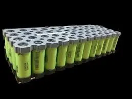
Step 2:- Then the terminals of the cells are connected according to the required sequences(seires or parellel) with the help of nikel strips by the spot welding process
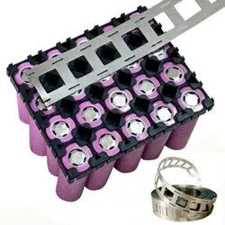
Step 3:- Then attach the heat sink to the battery pack & then the terminals are taken out and connected to the BMS
CONCLUSION
The design calculation for the battery pack was carried out and calculated and a table has been made for the same. The steps involved in the making of the battery pack have been listed out.