Project 1 Mechanical design of battery pack
EV LIVE BATCH 21
Battery pack capacity: 18 kWh
Cell: ANR26650M1-B
Prepare a detailed battery pack drawing along with its enclosure. State your assumptions.
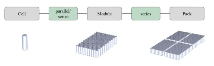
A battery pack is a device that stores electrical energy to provide power to an electrical system, such as an electric vehicle (EV) or an energy storage system (ESS). The energy is stored in cells that are all connected to one another in the battery pack. Battery packs are made of multiple, smaller sections called battery modules (or sub packs). These modules include a smaller number of cells connected in series and parallel. To provide sufficient power, battery packs require a minimum voltage level which a single cell cannot achieve. Multiple cells are therefore connected in series to boost voltage. Some designs use small-capacity cells. To achieve the desired battery energy, cells are connected in parallel to boost capacity. Cells connected in parallel provide power as if they were a single, larger cell.
Datasheet for Cell: ANR26650M1-B is given as,
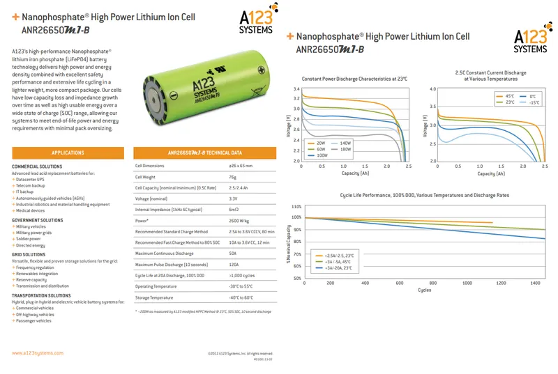
Accordingly, given cell is a Lithium Ion Phosphate Cell ANR26650M1-B, parameters can be listed out as,
Voltage: 3.3 Volts
Capacity: 2.5 Ah
Energy: 8.25 Wh
Specific Power: 2600 W/kg
Impedance (1KHz AC Typical): 6 mΩ
Max Continuous Discharage: 50 A
Max Pulse Discharge Current >50% SOC (10s): 120 A
Recommended Standard Charge: 2.5 Amps
Max Charge Rate: 10 Amps
Max Pulse Charge Current <50% SOC (10s): 25 A
Dimensions: diameter = 26 mm = 0.026 m
length = 65 mm = 0.065 m
Mass: 76 g
now, for designing a 18KWh battery, is the total energy of a battery pack to be delivered for all the operations needed by a vehicle, depend upon the operating voltage and Ampere Hour capacity of the battery.
firstly, for single cell, with Voltage = 3.3V and Capacity = 2.5 Ah,
energy of single cell = V*Capacity = 3.3 * 2.5 = 8.25 Wh
so, total number of cells for a battery pack required to deliver 18KWh (18000 Wh) of energy can be calculated as,
Total No. of cells = Battery pack energy / single cell energy
= 18000 / 8.25
= 2182
Now, Assume that we are designing battery pack voltage to be 120 V. As considering higher voltage range, current gets reduced with reduction in losses and also the cables can be used with smaller cross section area.
no. of cells that have to be connected in series are,
Series Connection = Battery pack voltage / single cell voltage
= 120 / 3.3
= 36
hence, no. of paralle connections can be given as,
Parallel connection = Total no. of cells / series connection
= 2182 / 36
= 61
So, battery pack can be designed for 36S 61P configuration.
and total battery pack capacity = no. of parallel connection * single cell capacity
= 61 * 2.5
= 153 Ah
Hence to deliver 18 KWh energy, battery pack configuration can be 120V, 153 Ah, 36s 61P.
now, considering single cell dimensions,
diameter = 26 mm = 0.026 m ; length = 65 mm = 0.065 m cylindrical shaped cell,
volume of a single cell = 3.14 * (0.026/2)^2 * 0.065
= 0.0000345 m3
also, volume of the battery pack = no. of cells * volume of a single cell
= 2182 * 0.0000345
= 0.075 m3
now, considering given weight of a single cell as 76 g = 0.076 Kg,
weight of the battery pack = single cell weight * no. of cells
= 0.076 * 2182
= 165.8 Kg
This weight of the battery is only considering the cell combination. Again electrical coonections, casing and other components will be taken into consideration for estimating the total pack weight.
now, single cell energy density = single cell energy / single cell volume
= 8.25 / 0.0000345
= 239130.4 Wh/m3
hence, total battery pack energy density = total pack energy / total pack volume
= 18 KWh / 0.075 m3
= 240 KWh/m3
so, the final specifications can be given for the battery pack as,
Total power capacity = 18 KWh
Battery Pack voltage = 120 V
Capacity = 153 Ah
Configuration = 36S 61P
Total No. of cells = 2182
Battery Pack weight = 165.8 Kg
Volume of the battery pack = 0.075 m3
battery pack energy density = 240 KWh/m3
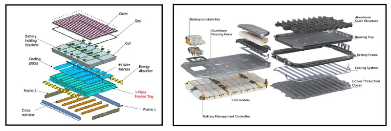
Further more, a complete battery pack can be constructed using following components along with enclosures,
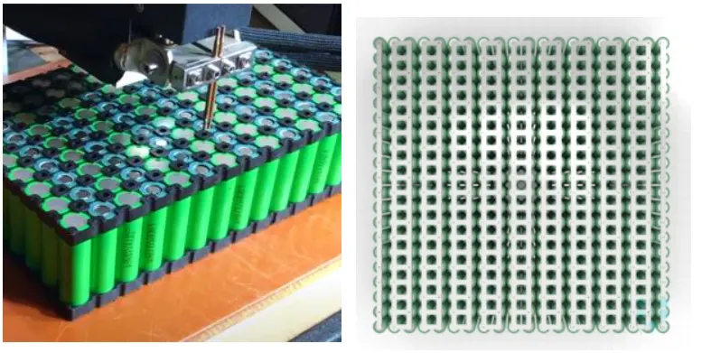
The required no. of cells are then placed in the cell holders also called as battery holder brackets. It is used for mechanical stability of cells against vibrations. It can be freely assembled in series and parallel. It can be used with high current copper bus, Fire insulation, conducive to heatdissipation and insulation in the working process of the battery pack. Overall it improves the safety of the battery pack.
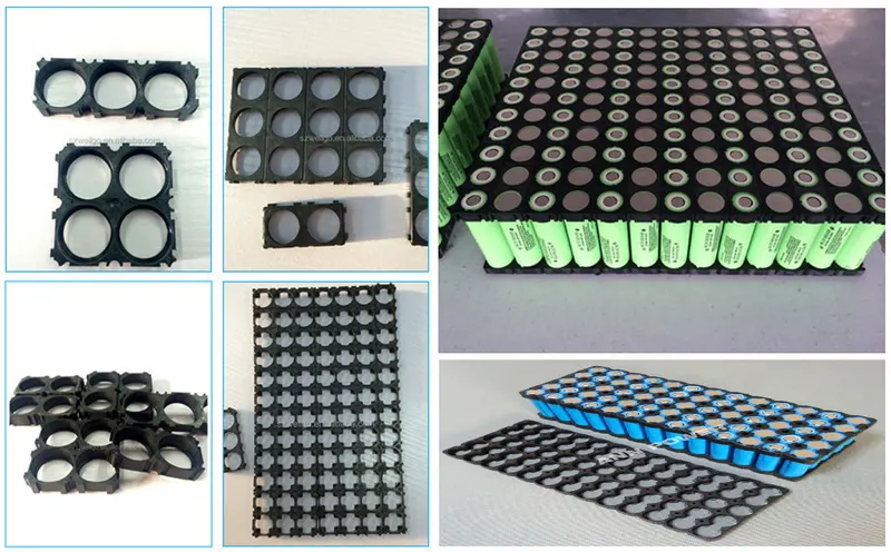
Electrical connectors such as busbars, wires, or other distribution conductors are used to make series or parallel connections between cells. These connections are typically done using laser welding. Busbar connections between modules can also be done mechanically using fasteners. For connections, Nickel has become most widely used in batteries due to its resistance to high voltages and conduction properties which means that the battery does not heat up upon heavy current flow. It is inexpensive and easily available and it can be easily weld.
Series and parallel connection configuration can be shown as,
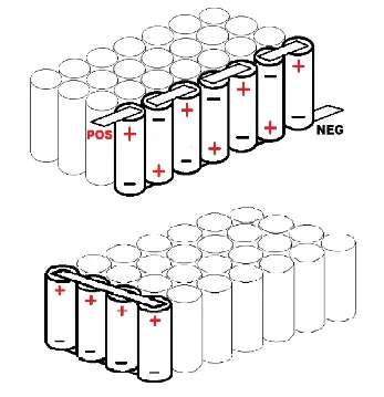
With this connection configuration, multiple cells can be connected to form a module and these modules then connected so as to configure a required battery pack.
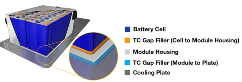
Thermal interface materials (TIMs) such as pastes, adhesives and gap fillers are inserted between battery components to join them mechanically while improving thermal properties between surfaces. With the rise of the structural battery packs, TIMs are becoming essential components.
The Housing is a rigid enclosure that protects the battery from environmental factors such as water, dust, and salt. It helps maintain a precise temperature and electrical insulation in the battery, and it prevents damages like rust and slow shorts.
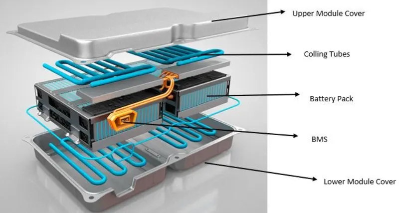
The Battery Management System (BMS) protects cells by monitoring key parameters such as voltages, currents, and temperatures. It is responsible for cell balancing (to maintain the optimal performance of the cells at the right voltage) and communicates with several systems such as engine management and temperature control. It also includes protection devices that can shut down the battery if needed.
The Battery Thermal Management System (BTMS) controls the thermal energy in the electric vehicle’s powertrain and cabin, providing cooling or heating as needed to meet the battery's thermal needs and protect the cells. The BTMS includes several components such as a heat exchanger, tubes, hoses, cold plates, pumps, valves, and temperature sensors.
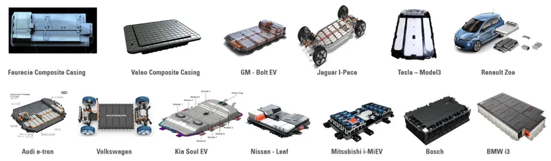
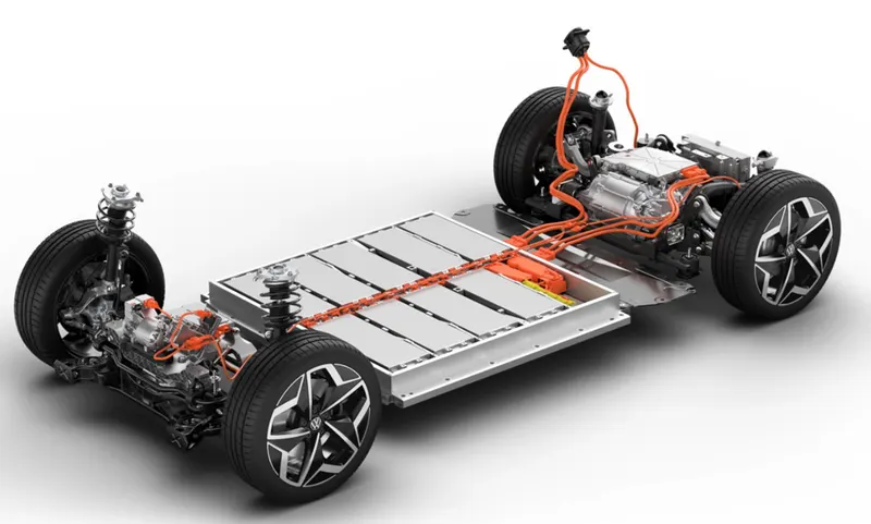
The Communications System ensures communication with other components in the electric vehicle. The most used protocol is CAN bus. Now, a typical vehicle with arrangement of battery module can be shown as,
Also, we can take example of different casing of battery pack for different vehicles.