Mechanical design of battery pack
OBJECTIVE: To prepare a detailed battery pack drawing along with its enclosure whose capacity is 18kWh and pack is to be made of ANR26650M1-B cells.
Specifications of cell:
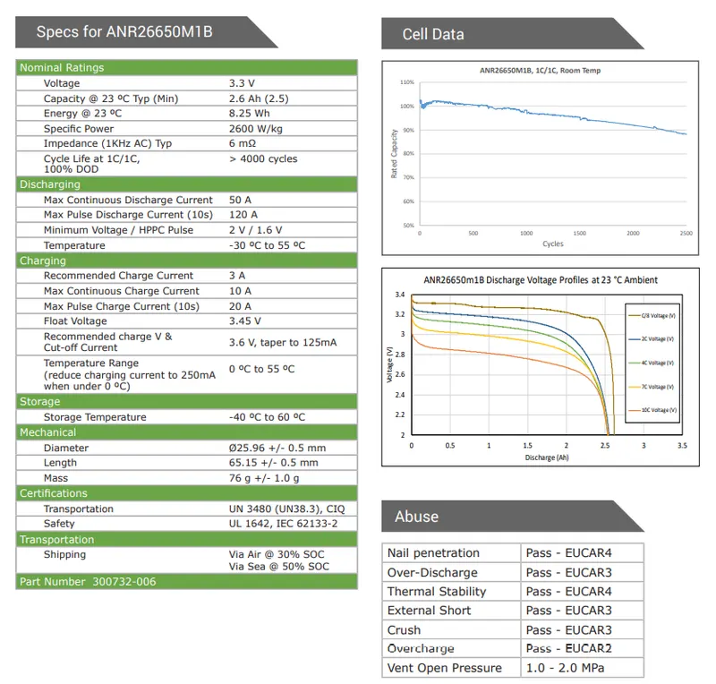
Nominal voltage of the cell = 3.3V
Nominal Ah capacity of the cell = 2.5Ah
Specifications of battery pack:
Capacity of battery pack = 18kWh
Let us consider that nominal voltage of the battery pack be 300V.
Then Ah capacity of the battery = `"Capacity of pack in Wh "/ "Nominal voltage of the pack in Volts" = 18000/300 = 60Ah.`
nPmS configuration:
Let us construct the battery pack in nPmS configuration which means 'n' number of cells are connected in parallel to form a module (Parallely Connected Module) and 'm' number of such modules are connected in series to complete the pack.
No. of cells to be connected in parallel to form a PCM = n = `"Nominal Ah capacity of the pack"/" Nominal Ah capacity of the cell" = 60/2.5 = 24.`
No. of PCMs to be connected in series to form a pack = m = `"Nominal voltage of the pack"/ "Nominal voltage of each cell or PCM" = 300/3.3 = 90.9 = 91.`
Therefore, n= 24 ; m=91 => 24P91S is the pack's configuration.
Total number of cells required for pack = n*m = 24*91 = 2184.
Dimensions of cell:
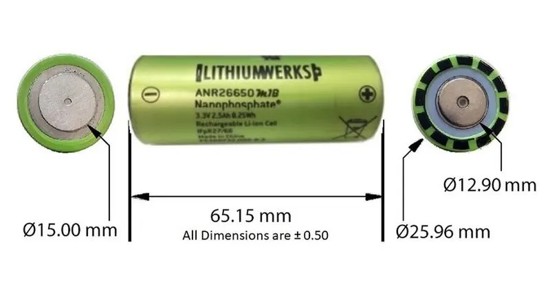
Height: 65.15 (+/- 0.5mm)
Diameter: 25.96 (+/- 0.5mm)
Mass: 76 grams
Total weight = No. of cells `xx` Weight of each cell = `2184xx76/1000`= `165.98`kg
So, `"Gravimetric Energy Density of the battery" = "Total capacity of the battery in Wh"/"Total weight of the battery in kg"=(18xx1000)/168.96=106.53 Wh//kg`
Now, we may not come to conclusion to calculate the Volumetric Energy Density(Wh/litre) of the battery because the cells in each module or part of them can be connected in different structures like rectangular, triangle or even in circular fashion. So, the volume of the pack varies depending upon the structure in which cells are connected.


STEPS TO BUILD A BATTERY PACK FROM CELL LEVEL :
- Initially, the cells are connected in series/parallel to form module and then modules are connected in parallel/series to form a pack of required capacity depending upon nSmP/nPmS configurations.
- Cell to cell connections are usually made through nickel strip of of thickness depending upon the cell's Ah capacity.
- These nickel strips are connected to the cells usually through spot welding.
- If the pack consists of more number of cells, then cell level fusing is employed.
- Finally, BMS is attached to the pack with required connections, which operates the pack in safe operating limits and estimates and calculates state of charge, distance to empty, etc of the pack.
Now, let us look at each step mentioned above briefly.
PARALLEL CONNECTIONS:
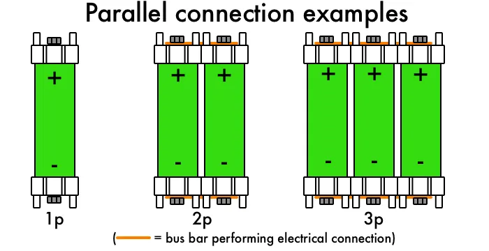
- In parallel connection of cells, all positive terminals of the cells are connected together and all the negative terminals are connected together.
- Here, in our 24P91S configuration, 24 no. of cylindrical cells are connected in parallel in each module (PCM) of total 91 modules.
SERIES CONNECTIONS:
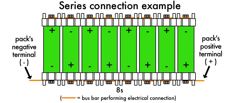
- In order to connect the cells in series, the positive terminal of a cell is connected to the negative terminal of next cell.
- Here, in our 24P91S configuration, 91 modules (PCMs) are connected in series by connecting the positive terminal of a module to negative terminal of next module.
CELL HOLDERS:
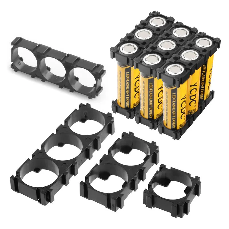
- Using cell holders makes your battery pack more solid.
- Cell holders provide critical spacing between the cells. This allows for much better cooling characteristics as compared to cells that are in direct contact with each other.
- Cell holders give your battery pack an element of vibration resistance.
CONNECTORS:
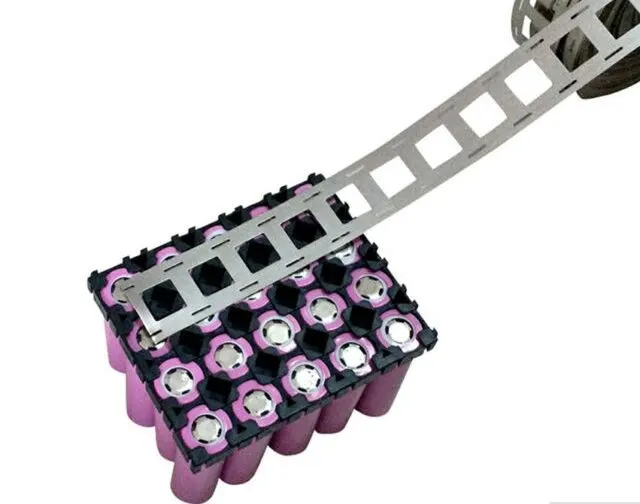
Nickel is commonly used as connectors for lithium ion batteries, due to an adequate combination of conductivity, solderability, strength, formability, weldability and corrosion resistance.
SPOT WELDING:
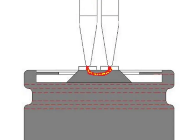
Spot Welding is when you send a very short pulse of high current through two pieces of metal so that they will melt together, and hopefully make a solid connection. We may have noticed that some of the nickel ribbon that is used as a bus material has a slot over each of the cell locations, and some does not.
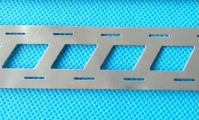
If the nickel ribbon has a slot, then the current is forced to travel through the cell (which is the shorter distance for the current to travel), and this can provide a solid weld with less energy (and less heat). Does spot-welding with no slot work? Yes, but when doing that, a large percentage of the current passes through the nickel strip from one welding probe to the other.
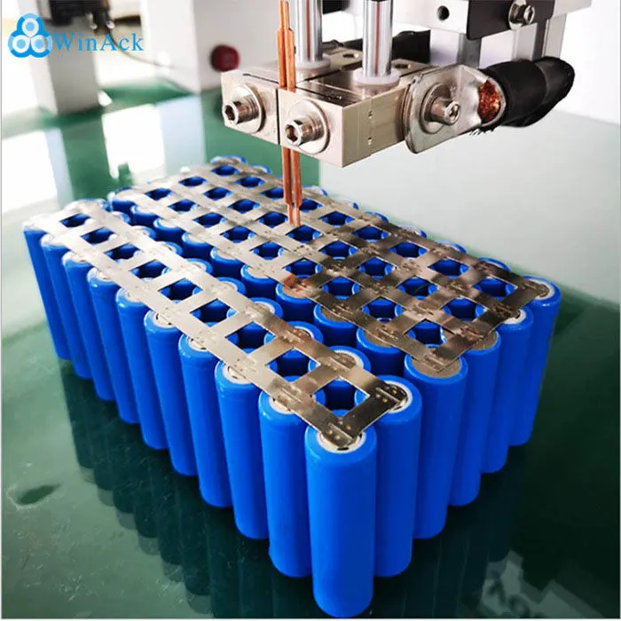
The following image shows positive tip of cylindrical cell on which current flowing between two spot welding probes. The slot down the center of the nickel ribbon forces the current to go through the cell tip.
CELL LEVEL FUSING:
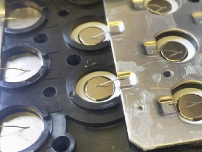
- If we are building a very large battery pack that could have hundreds, even thousands of cells. It’s a good practice to incorporate cell-level fusing into the pack. In battery packs like this, each and every cell has its own fuse.
- In applications where safety is critical, cell-level fusing is the way to go. In these setups, there is typically a large, copper bus-bar that each cell is connected to with fuse wire. Fuse wire is specifically sized wire that is made to withstand a certain current threshold.
- When this threshold is crossed, the fuse wire will burn up in a controlled manner. When this happens, the path of current is broken, which effectively removes the cell from the circuit.
BATTERY MANAGEMENT SYSTEM:
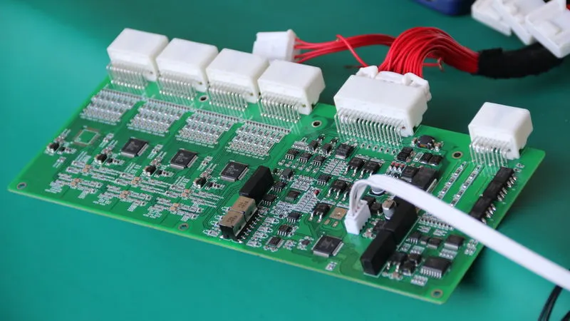
If a battery pack is connected without BMS, then we have to encounter the following main problems:
- Inherently, there is no intellengence for cells, the cells delivers the current required by the load even if it is larger than rated current which will decrease cell's health, thermal runaway may even occur in some cases.
- No data regarding the 'state of charge' of the pack which is essential to estimate 'distance to empty' for an electric vehicle.
So, now you go to know why BMS is required for a pack. Let us look into the operations of the BMS:
- Overcharge Protection: A BMS Monitors the voltage of all cell groups. When any one of those cell groups reaches maximum voltage charging is stopped. This prevents your cells from being damaged from being overcharged, and also helps prevent fires.
- Cell Balancing: If one or more of your cell groups are at a higher voltage than the others, a BMS uses a circuit and small balance resistors to lower the voltage of any high cells.
- Over-Discharge Protection: A BMS disables the battery pack when any cell's voltage falls below a certain threshold. Remember, if a cell goes much lower than that, it will get damaged.
- Over-Current Protection: Another critical job of a BMS is to make sure the battery pack is not put under too much stress. So, every BMS has a maximum current that, if achieved, will turn the battery pack off. Over-current protection applies to both charging and discharging the battery pack.
- Short Circuit Protection: A short circuit is equivalent to a 0 Ohm load. When a short circuit condition is created, the only resistance to the flow of current will be the very low resistance of the conductor (wire or nickel) and cell itself. So, because a short-circuit condition creates an over-current condition, any BMS that has over-current protection also has short-circuit protection.
REFERENCES:
ANR26650M1-B cell's datasheet and images
Series and Parallel connections images
Current flowing while spot welding & nickel strip & cell level fusing images