Project 1 Mechanical design of battery pack
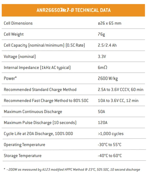
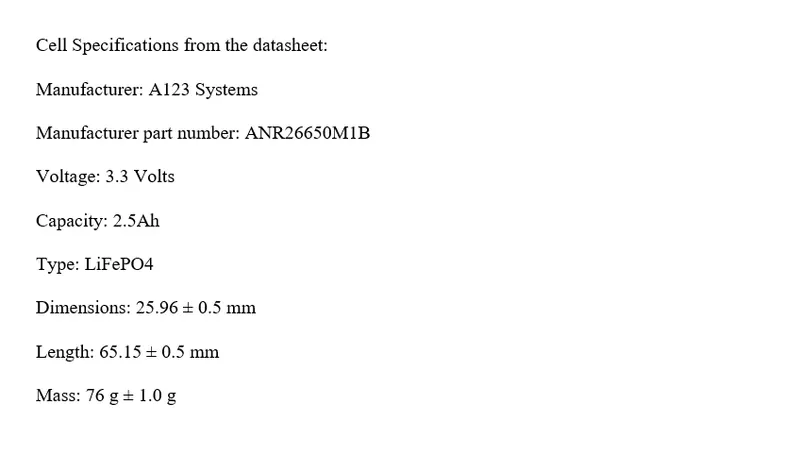
Aim: To prepare a Battery pack of capacity 18 kWh with an ANR26650M1-B cell.
Solution:

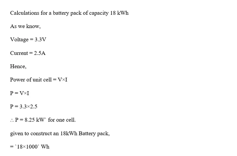
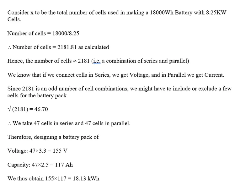
Battery Pack Drawing of Configuration of 47S47P:

General steps followed to design a battery pack:
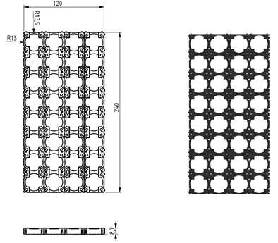
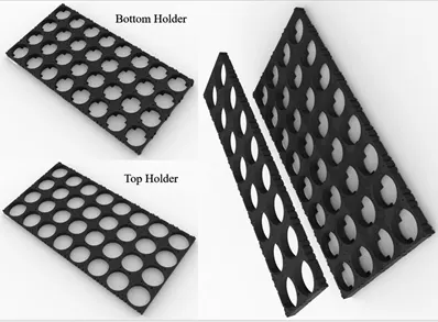
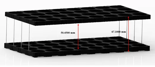
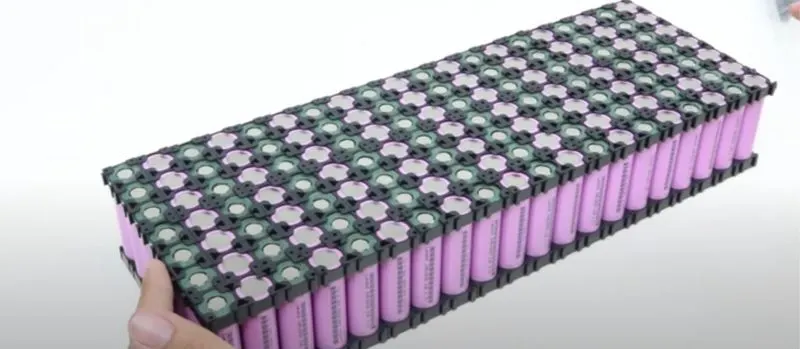
1 - Design of cell holder (Bottom and Top)
The main function of a battery holder is to keep cells fixed in place safely and securely also it is used to keep cells in a proper arrangement so that there will be a decrease in mechanical vibration and a better thermal runway in between the gaps of the cell. Most of the cell holder is made up of polypropylene or nylon bodies rated for 80–100 °C.
2 - Inserting cells inside the holder (Bottom and Top)
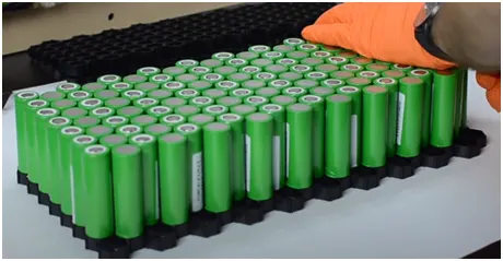
Insert the cells inside the connectors with positive and negative poles kept alternatively in adjacent rows.
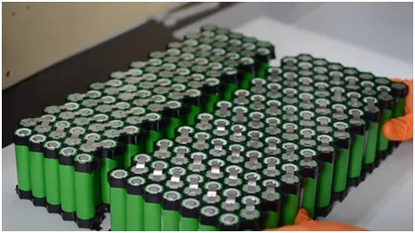
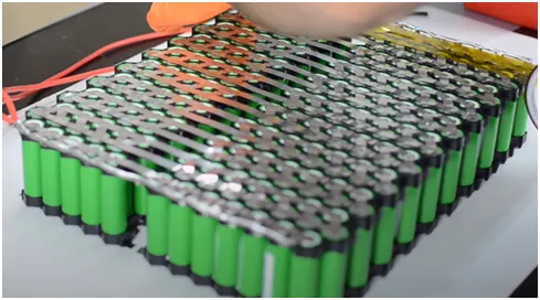
3 - Spot welding should be done with nickel strips to make a series connection between the cells as in the figure below
After making series connections, connect the strings in parallel and complete the connection as shown below
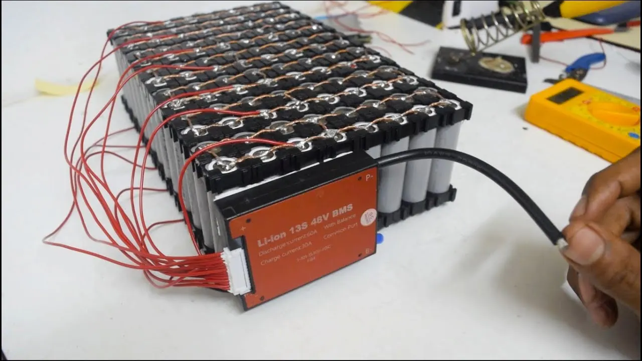
4 - Install BMS for the battery pack as shown
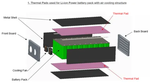
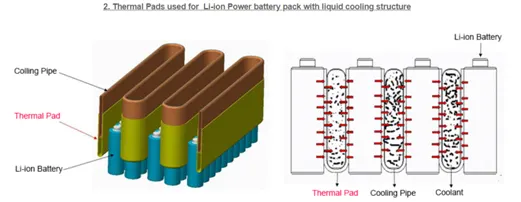
5 - Install the cooling structures for air cooling/ liquid cooling as shown in the figure
6 - Install the battery pack inside the enclosure
Safety:
Lithium-ion cells should be charged according to the battery manufacturer's specifications. Under no circumstances should cells be subject to over-charge, over-discharge, or short circuit.
Cells should not be subjected to mechanical abuse or stress and should not be subject to high-temperature charging
Cells should be stored in a practically discharge state, typically between 20-40%, and used in a battery pack that should be individually monitored and controlled by a BMS to prevent electrical stress.
The battery should be designed to allow passive cooling of individual cells and cell spacing should be designed to prevent thermal runaway from spreading from cell to cell.
References: ANR26650M1-B cell datasheet