Project 1 Mechanical design of battery pack
Objective -
To prepare a detailed battery pack mechanical design for the batteer pack energy of 18 kWh of the cell ANR26650M1-B.
Theory -
EV Battery Pack Design -
- For designing a battery pack, a cell is connected in combination of series and parallel connections known as modules.
- These modules are combined to form a battery pack.
- To design a battery pack, the number of cells required must be known for series as well as parallel connections.
- To increase the voltage level cells are connected in series .
- To increase the current capacity cells are connected in parallel.
- As the number of cells required is high, so they required large space.
- For a battery pack design to be reliable it should be able to address the issues relating to thermal stability, vibration isolation and impact resistance.
- It should also minimise the mechanical and thermal interactions between different units in batter pack.
- Design elements that can be optimized readily to achievethe required level of protection without much impact on available resources are called Control Factors.
- Some of the crucial control factors are
- Battery Cells and Spacer Type
- Battery Cooling System
- Insulation Coating Thickness
- Battery Cell Types -
Battery Cell Type has a significant influence of design of the battery packs. It is relatively easier to improve volumetric efficienc of the battery pack by packaging large quantities of smaller cells. Battery cell types are- Prismatic
- Pouch
- Cylinderical
- Spacer Types -
Compactness of packaging design also has an appreciable impact on thermal performance of the battery pack.
- Ladder or Linear
- Multi rows
- Face Centered cubic packing
- Packing cells in tube




Linear Multi Rows FCC Packing Cell in tube
- Thermal Runaway Protection -
- Manufacturing defects or events such as physical abuse and internal short circuit can push a battery cell into a state of thermal runaway.
- It can cause the battery to vent large quantities of flammable gases, emit jet of effluent materials and even combust spontaneously.
- The damage to property and safety risks to the vehicle passengers and vehicle can be minimised by strategically controlling the direction of release of hot fumes and gases from the packaging.
- The damages can also be controlled by restricting thermal interaction between different entities of the battery pack.
- Structural stability -
- The solid structure created through metallic or rigid plastic casings typically used for the prismatic and the cylindrical battery cells prevents foreign objects from penetrating the electrochemical system.
- The mettalic casings provide a greater degree of tolerance to pressures generated inside the battery cell because of gas generation and venting.
- Crash Protection -
Maintaining structural integrity of the battery pack during crash conditions is another conditions for EV designers. For this purpose two packaging architecture are primarily utilised- T-shaped - It enables the battery modules to be arranged inside the primary safe zone of the vehicle. It prevents the battery pack fromdirect frontal impact and side frontal loads through usage of vehicle structure.
- Floor Configuration - It maximise the available cabin space to be used either by the vehicle occupants themselves or for storing their luggage. It increases vehicle stability by lowering its center of gravity and also reduces the ground clearance of the vehicle thus exposing the battery pack to dangers from bottom impact.
- Vibration Isolation -
- Travelling over uneven surfaces, such as holes, grade crossings, produces shocks that cause vertical vibrations.
- As a result, dynamic mechanical loads develop on the electrical subsystems such as terminal connectors and bus bars in a battery pack, which can result in loss of electrical continuity and fatigue of the casting.
- Weight distribution of the vehicle can also influence the degree of vibration isolation and ride quality.
- A battery mounting frame structure for achieving uniform vehicle weight distribution and to maintain a low centre of gravity.
- It is possible to realize an optimum weight distribution and thereby vibration isolation by simply modifying the number of battery stacks in the group without making major alterations to the dimensions of the battery mounting frame.
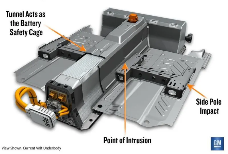
Fig - Crash Protection T-shaped architecture
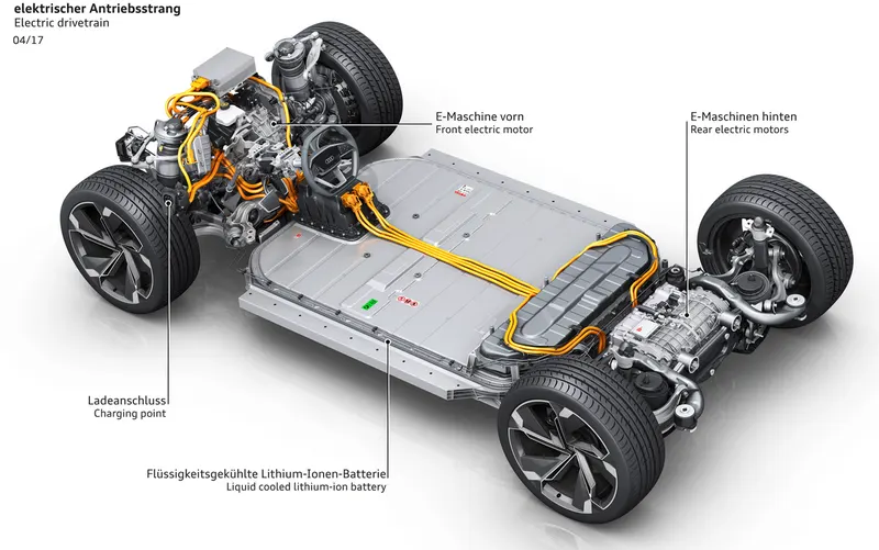
Fig - Crash Protection Floor Configuration
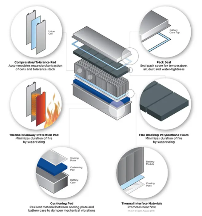
Fig - Vibration Isolation
Cell ANR26650M1-B -
- The LithiumWerks ANR26650M1-B is the next generation of A123 Systems’ pioneering 26650 cylindrical cell
- It comes with greater power and energy density and lower impedance.
- This versatile lithium ion cell is suitable for a wide variety of applications and system designs.
- Proven performance in the toughest conditions, combining durability, reliability, and safety, the ANR26650 cell offers an excellent combination of price-performance.
- Cylindrical Cell Primary Applications -
- Portable high power devices
- Stationary battery backup systems
- Grid stabilization energy storage systems
- Commercial truck and bus hybrid electric vehicles (HEVs)
- Lithium Ion Cell Benefits -
- Power : Over 2,600 W/kg and 5,800 W/L
- Safety : Excellent abuse tolerance and environmentally friendly
- Life : Excellent calendar life, 10X cycle life vs. conventional lithium ion
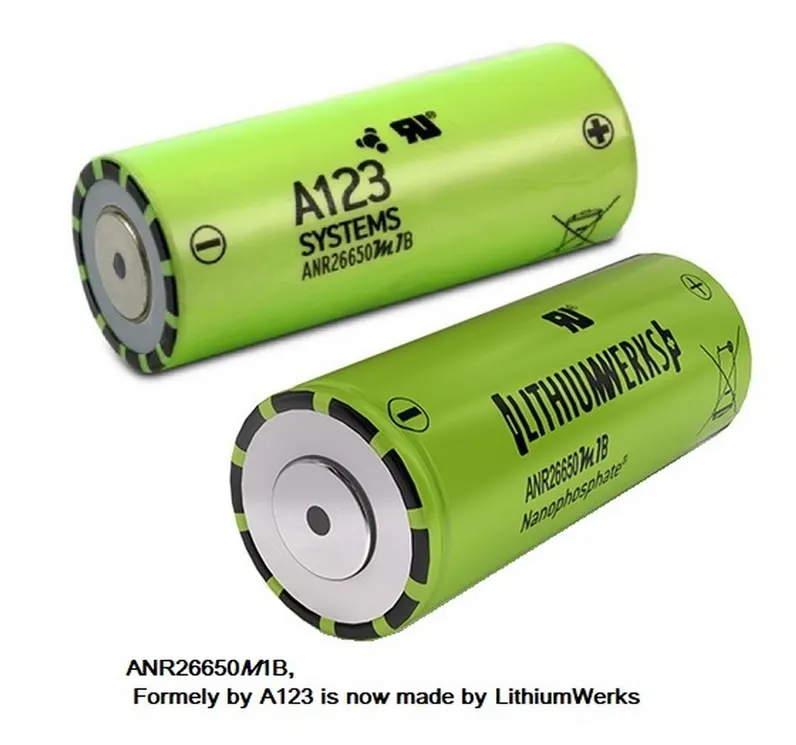
Cell ANR26650M1-B Specifications -
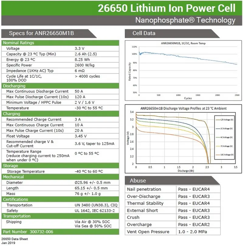
- Nominal Ratings
| Voltage |
3.3 Volts |
| Capacity |
2.5 Ah |
| Energy |
8.25 Wh |
| Specific Power |
2600 W/kg |
| Impedance (1 kHz AC Typical) |
6 mΩ |
| Cycle Life at 1C/1C, 100% DOD |
>4000 cycles |
| Cell Type |
26650 Lithium Ion Power Cylindrical Cell |
- Discharging
| Max Continuous Discharage |
50 A |
| Max Pulse Discharge Current >50% SOC (10s) |
120 A |
| Minimum Voltage |
2 V |
| Temperature |
-30ºC to 55ºC |
- Charging
| Recommended Standard Charge |
2.5 A |
| Max Charge Rate |
10 A |
| Max Pulse Charge Current <50% SOC (10s) |
25 A |
| Float Voltage |
3.45 V |
| Recommended charge V & Cut-off Current |
3.6 Volts, taper to 125mA |
|
Temperature |
0ºC to 55ºC |
- Mechanical
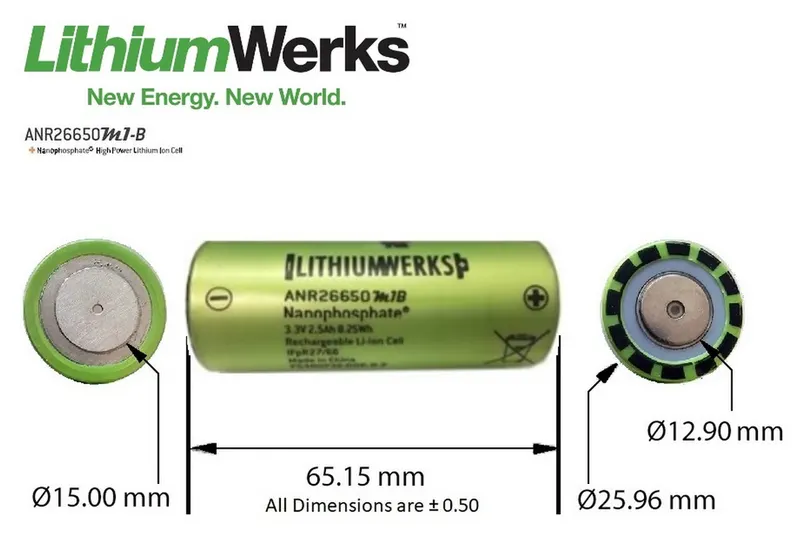
| Diameter |
Ø25.96 +/- 0.5 mm (1.0") |
| Length |
65.15 +/- 0.5 mm (2.6") |
| Mass |
76 g |
Cell Characteristics -
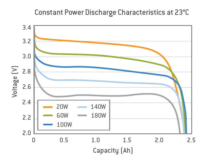
- Constant Power Discharge Characteristics -
- The voltage vs capacity graph for discharging of battery at 23ºC is shown below -
- This graph shows the characteristics for discharging at different power.
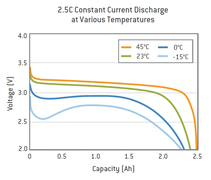
- Constant Current Discharge Characteristics -
- The voltage vs capacity for discharging at constant current rate of 2.5C is shown below.
- This graph show the characteristics of discharging at different temperature.
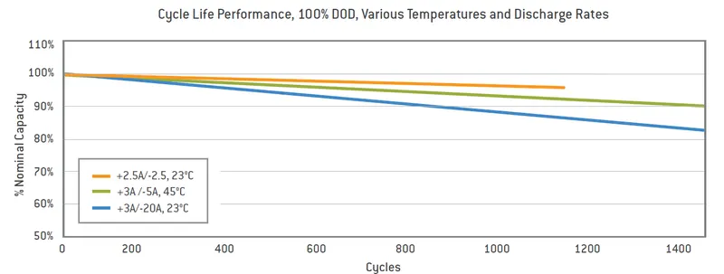
- Cycle Life Performance -
- This graph shows the peformance of battery cycles for different temperature and discharge rates.
- For this graph, the battery is charged and discharged completely.
Calculations for EV battery pack -
Given, battery pack energy = 18 kWh
Let the battery pack voltage be 600 V.
Battery Pack Capacity = Pack energy / Pack Voltage = 18*10^3/600 = 30 Ah
No. of cells required in series = Battery Pack Voltage / Cell Voltage = 600/3.3 = 181.81
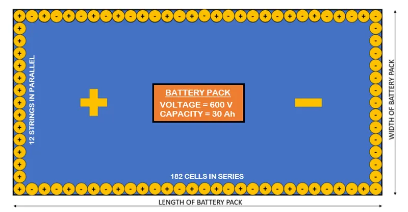
182 cells are required in series connection.
No. of strings required in parallel connection = Battery Pack Current Capacity / Cell Capacity = 30/2.5 = 12
12 strings are required for parallel connection.
Total no. of cell required = 182 * 12 = 2184
Weight of Battery Pack = Total no. of cell * Individual cell weight = 2184 * 76/1000 = 165.984 kg `approx` 166 kg
Specific Power of battery pack = Pack Energy / Pack Weight = 18*10^3 / 166 = 108.43 Wh/kg
Let the battery pack is connected in simple manner i.e. no stacking is done.
Length of battery pack = No. of cell in series * Cell diameter = 182 * 0.02596 = 4.72 m
Width of battery pack = No. of cells in parallel * Cell diameter = 12 * 0.02596 = 0.3115 m = 31.15 cm
Area of the battery pack = Length of battery pack * Width of battery pack = 4.72 * 0.3115 = 1.47 m^2
Let powertrain energy consumption be 200 Wh/km
Range of the vehicle = Energy of the battery pack / Powertrain energy consumption = 18000/200 = 90 km
References -
- Cell ANR26650M1-B - A123batteries.com
- Mechanical Design - Mechanical Design of Battery Pack for Electric Vehicle