Project 1 Mechanical design of battery pack
Aim : To prepare the detailed battery pack drawingalong with its enclosure and to calculate the necessary perameters
Here they asked me to prepare a detailed battery pack drawing along with its enclosure of the ANR26650M1-B
So for this we need the specification of the particular battery which is available in its data sheet of
ANR26650M1-B
So I am calculating all the parameters of this battery pack based on this data sheet only
Below I am attaching the image of the parameters of the battery which are provided in the data sheet
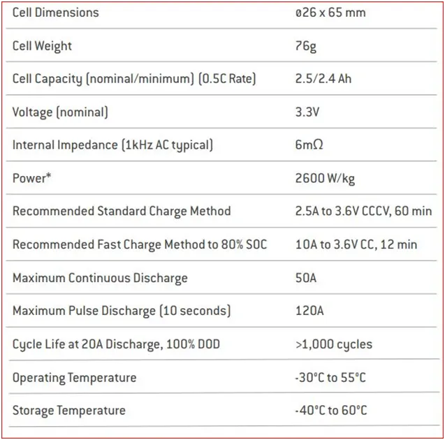
These are the some of the important parameters which are mention about the ANR26650M1-B
Battery model
Below I am attaching the image of the characteristics graph in between the voltage and capacity i.e., constant power discharge characteristics at 230c. And this characteristics are taken from the different cell values and its power ratings.
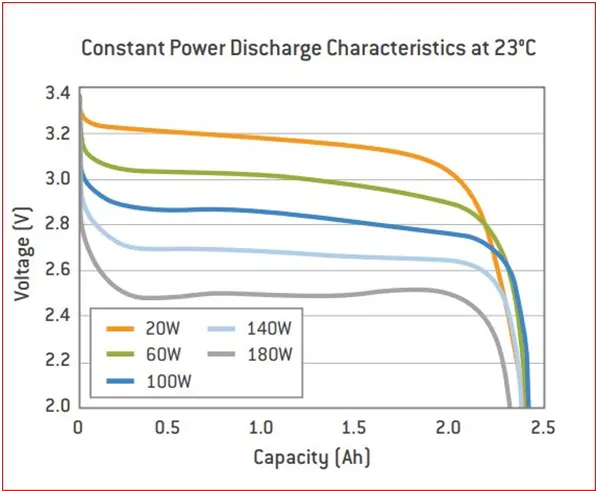
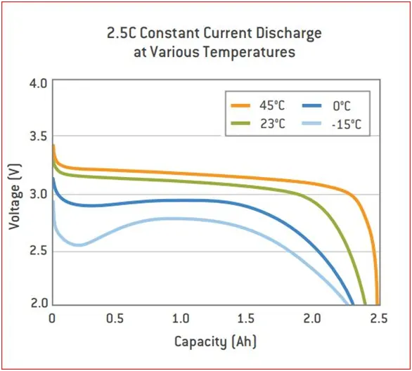
And now let’s see the characteristics of constant current discharge at various temperature
Below I am attaching the image of the constant current discharge at various temperature. This shows the current discharge characteristics at different temperature
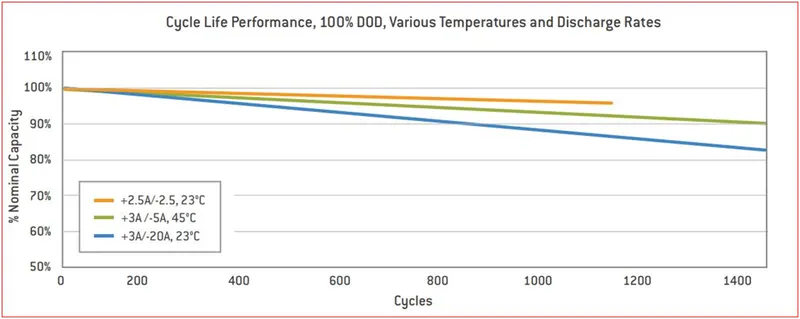
So now let’s look the cycle life performance, 100% depth of discharge, various temperature and discharge rates of cell
Below I am attaching the image of the following characteristics which is available in the data sheet
Batteries are designed so that the energetically favorable redox reaction can occur only when electrons move through the external part of the circuit. A battery consists of some number of voltaic cells. Each cell consists of two half-cells connected in series by a conductive electrolyte containing metal cations.
One half-cell includes electrolyte and the negative electrode, the electrode to which anions (negatively charged ions) migrate; the other half-cell includes electrolyte and the positive electrode, to which cations (positively charged ions) migrate. Cations are reduced (electrons are added) at the cathode, while metal atoms are oxidized (electrons are removed) at the anode. Some cells use different electrolytes for each half-cell; then a separator is used to prevent mixing of the electrolytes while allowing ions to flow between half-cells to complete the electrical circuit
The voltage of a battery is a fundamental characteristic of a battery, which is determined by the chemical reactions in the battery, the concentrations of the battery components, and the polarization of the battery. The voltage calculated from equilibrium conditions is typically known as the nominal battery voltage. In practice, the nominal battery voltage cannot be readily measured, but for practical battery systems (in which the overvoltage’s and non-ideal effects are low) the open circuit voltage is a good approximation to the nominal battery voltage.
Since the electric potential (voltage) from most chemical reactions is on the order of 2V while the voltage required by loads is typically larger, in most batteries, numerous individual battery cells are connected in series. For example, in lead acid batteries, each cell has a voltage of about 2V. Six cells are connected to form a typical 12V lead acid battery.
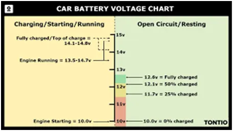
Now let’s get in the considered model or referred type of the battery and its calculations
Below we can see the ANR26650M1-B battery image and its measurements

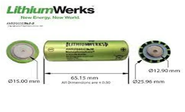
The above image shows us the finished look of ANR26650M1-B battery cell and the measurements of the cell
Now let’s calculate the electrical and the mechanical parameters of the battery pack which is helpful to say the total electrical specification of the pack and the calculations which are helpful for the battery pack packing in the module
PARAMETERS CALCULATIONS :
For this calculation all the data is taken from the data sheet of the ANR26650M1-B battery
Cell dimensions = 26mm X 65mm
Cell weight = 76g
Nominal cell capacity = 2.5Ah
Nominal voltage = 3.3v
Power = 2600W/kg
Continuous C-rate = 10
Peak C-rate = 24
Volume of cell (cylindrical) = πr2h
Height of the cell = 65mm
= 0.065m
Radius of the cell = D/2
= 26/2
= 13mm = 0.013m
Volume of the cell = πr2h
= 3.14 X 0.0132 X 0.065
= 3.45 X10⁻⁵ m3
: volume of the cell = 3.45 X10⁻⁵ m3
→ now let’s calculate the electrical & mechanical parameters :
Cell energy = 8.25wh
Now let’s calculate total pack energy
- Battery pack energy density = cell energy / volume of cell
= 8.25 / 3.45 X10-5
= 239130.43
Battery pack energy density = 239130.43wh/m3
- Gravimetric energy = cell energy / weight of cell
= 8.25 / 0.076
= 108.55
Gravimetric energy = 108.55wh/kg
Now let’s make a battery pack capacity of 18KWH (18000wh)
Let’s assume the battery pack voltage required is 297V
- Number of cells connected in series :
= battery pack voltage / voltage of each battery cell
= 297 / 3.3
= 90
Number of cells connected in series = 90 cells
- Energy of a string = number of cells connected in series X energy of battery pack
= 90 x 8.25
= 742.5
Energy of string in series = 742.5wh
- Number of cells connected in parallel:
= battery pack capacity / energy of string in series
= 18000 / 742.5
24.24
Number of cells connected in parallel = 25 cells
- Battery pack capacity = no. of parallel cells connected X capacity of call
= 25 X 2.5
= 62.5
Battery pack capacity = 63Ah
- Total number of cells in a battery pack
= no. of cells in series X no. of parallel cells
= 90 X 25
= 2250
Total number of cells in battery pack = 2250 cells
- Weight of the battery pack = total no. of cells in battery pack X weight of cell
= 2250 X 0.076
= 171
Weight of the battery pack = 171kg
- Volume of the battery pack = total cells in battery pack X volume of cell
= 2250 X (3.45 X10-5)
= 0.077625
Volume of the battery pack = 0.077625m3
- String peak current = peak C-rate of cell X cell capacity
= 24 X 2.5
= 60
String peak current = 60A
- Battery pack peak current = string peak current X no. of cells connected in parallel
= 60 X 25
= 1500
Battery pack peak current = 1500A
- Battery pack peak power = battery pack peak current X battery pack voltage
= 1500 X 297
= 445500W
Battery pack peak power = 445.5KW
- String continuous current = continuous C-rate of a cell X capacity of a cell
= 10 X 2.5
= 25
String continuous current = 25A
- Battery pack continuous current = string continues current X of cells connected in parallel
= 25 X 25
= 625
Battery pack continuous current = 625A
- Battery pack continuous power = battery pack continuous current X battery pack voltage
= 625 X 297
= 185625W
Battery pack continuous power = 185.6KW
By now the calculation of all the parameters are completed. Now let’s arrange all the parameters in a single table.
|
Name of the parameter |
Value of the parameter |
|
Volume of cell |
3.45 X10⁻⁵ m3 |
|
Volume of the battery pack |
0.077625 m3 |
|
Weight of the battery pack |
171kg |
|
Cell energy |
8.25wh |
|
Battery pack energy density |
239130.43wh/ m3 |
|
Gravimetric energy |
108.55wh/kg |
|
Number of cells connected in series |
90 cells |
|
Number of cells connected in parallel |
25 cells |
|
Energy of string in series |
742.5wh |
|
Battery pack capacity |
63Ah |
|
Total number of cells in battery pack |
2250 cells |
|
String peak current |
60A |
|
Battery pack peak current |
1500A |
|
Battery pack peak power |
445.5Kw |
|
String continuous current |
25A |
|
Battery pack continuous current |
625A |
|
Battery pack continuous power |
185.6Kw |
Now lets get into the enclosure procedure :
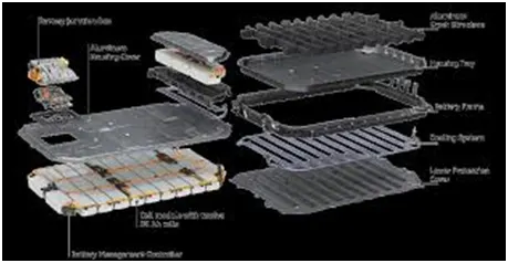
The enclosure is able to secure the modules during sudden accelerations or decelerations from crash scenarios, allows for air flow to cool the cells, and allows for convenient serviceability of the modules. As the batteries are connected in series and parallel according to the capacity of the pack. After the battries are connected they are assembeled in the cells.
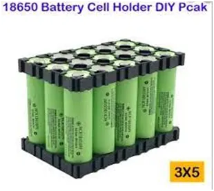
Battery holders :
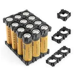


The above figure shows the battery cells holder. A battery holder or a battery mount is an integrated or separate cavity to hold cells. If it is a separate compartment, it can be attached to a cell-powered device. It is used to hold the cells securely and power the device it is attached to. The primary function of a battery holder is to keep cells fixed in place safely and securely while conveying power from the batteries to the device in question.
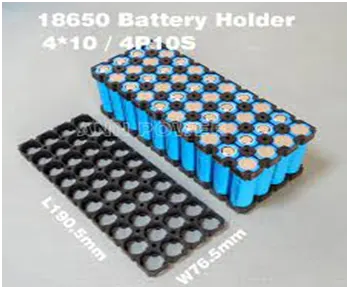
Nickel strips :
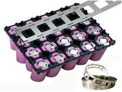
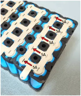
Nickel strip is generally used in battery building. Its due to its efficiency of usage in spot welding and soldering as well its high corrosion resistance over time. It has good properties and excellent resistance to many corrosive environments. The pure nickel will never get rust after it applied to battery packs.

Nickel strip is generally used in battery building. Its due to its efficiency of usage in spot welding and soldering as well its high corrosion resistance over time. It has good properties and excellent resistance to many corrosive environments. The pure nickel will never get rust after it applied to battery packs. It won’t affect the current transfer between batteries.
Pure nickel strips are the material you want, but many vendors swap out it for nickel-plated steel strips, which are poorer and have greater resistance – not suitable for most battery projects.
Battery enclosure :
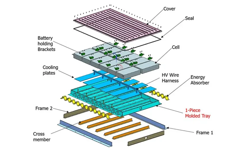
Continental Structural Plastics has developed one-piece, compression-molded composite covers, an innovative fastening system and a range of material options to meet OEM needs.
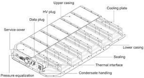
It consists of a housing tray with crash structure, housing cover, and underbody protection. Today, housings for high-voltage batteries are primarily made of extruded steel or aluminum profiles.
The most common battery enclosures are made from plastic materials that are resistant to alkaline solutions and have a high impact strength. Metal housings are sometimes used, but metal requires careful design and assembly to avoid shorting of the cells in the battery pack. Aluminum is not recommended for enclosures because if cell leakage does occur, the electrolyte will react with the aluminum.
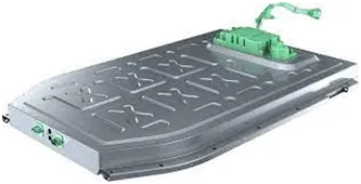
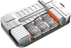
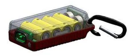
The battery enclosure may also have a significant impact upon battery life if not designed properly to prevent the cell's temperature from rising significantly in overcharge. Good battery form factor allows for air movement around cells to help reduce temperature rise in overcharge. A four-cell stick (cells connected end-to-end) has a significantly greater surface area for heat dissipation and therefore lower overcharge temperature than would four cells in a square configuration.
Final form of the pack :
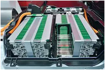
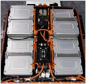
In the following figure we can see the arrangement of modules of the battery pack which are used in electric vehicles and according to the company vehicle designs the arrangement may be varied
so the enclosure procedure, the electrical and the mechanical parameters of the battery pack are also calculated of the ANR26650M1-B is done with the relevent images
Note :
below i am attaching the data sheet of the ANR26650M1-B battery model for the reference
Thank you ;
B. V. N. SANDEEP.