Project 1 Mechanical design of battery pack
Battery pack capacity: 18 kWh
Cell: ANR26650M1-B
Prepare a detailed battery pack drawing along with its enclosure. State your assumptions.
Introduction:
Mechanical design of Lithium-ion batteries are highly efficient and more reliable than other batteries making them a good choice for electric vehicles. Despite the batteries being highly rated, some of the main deterring issues they face include; the thermal stability of Li-Ion batteries and high manufacturing costs. Many players and car manufacturers in the electric vehicle industry are today focused on optimizing battery designs. The main result most of them strive to achieve is to have batteries with increased energy storage that are safe, light in weight, and highly efficient. Most manufacturers aim to produce batteries that have regulated thermal conditions to improve the performance of EV battery packs.
Mechanical Design of Electric vehicle battery pack:
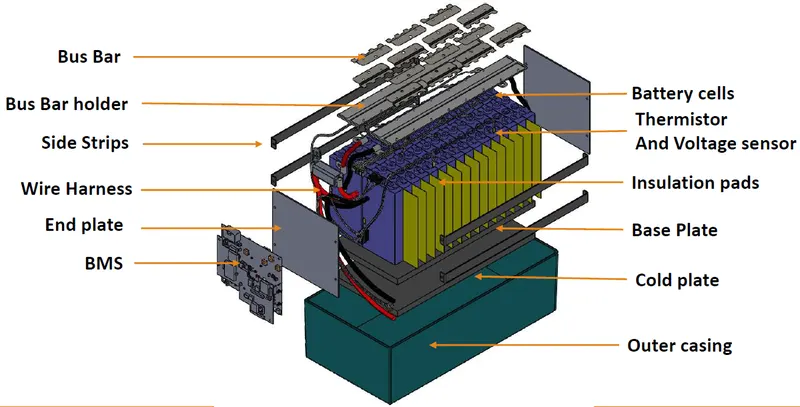
Electric vehicles' car battery packs have a complex system that consists of various components. Therefore, an efficient battery pack design is crucial for the success of an electronic vehicle. An EV battery pack contains various electro-mechanical systems that communicate with different sub-systems within the car. They also communicate simultaneously with multiple parameters through various interfaces. These interfaces include; mechanical, structural, thermal, electrical, control, and support.
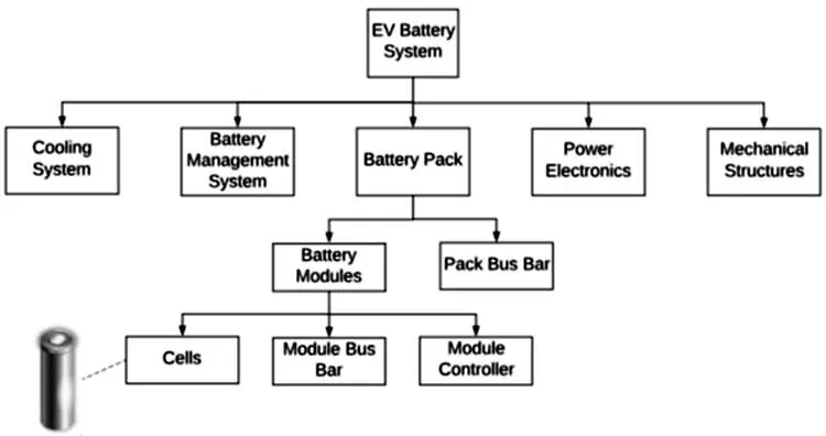
●Mechanical Communication through the various interfaces influences the reliability and safety of the battery pack, making it safer to drive an EV. It represents all the mechanical design features of an EV. These include damping pads, exhaust valves, cell spacers, and different seals that have been integrated within the battery pack for safety reasons.
●Structural- it is the general containment of the battery pack. It contains structural features such as tie-rods, end-plates, and cross-members that function as protective members in the battery pack. Therefore, a good battery pack has to have a case and a cover to prevent it from external and environmental factors (humidity, dirt, vibrations, and crash effects).
●The thermal interface controls the temperatures within the Lithium-ion battery cell between 25 and 30 degrees Celsius. It also ensures there is uniform thermal distribution within the battery pack to maximize energy capacity. It contains systems such as pumps, heat exchangers, coolants, and fans.
●The electrical interface generates and transmits a certain voltage to meet the power requirements of an EV. Its electrical circuit consists of a bus bar and cables, fuse, contactors, circuit breaks, and relays.
●Control systems monitor and regulate the state of a battery pack. The features are the Battery Management System and sensors used to measure current, voltage, humidity, pressure, and temperature within a battery pack.
●Support interface is the support the battery pack gets from the vehicles. It is commissioned through mounting brackets and axles to help achieve the required degree of vibration isolation. Other systems include the chassis, floor, and car seats.
Electric Vehicle Battery Pack Components
An electric vehicle needs an enormous amount of power to perform effectively. An EV battery pack may vary slightly depending on the type of electric vehicle. But generally, these vehicles' battery packs contain three components; cells, modules, and a pack. An EV contains countless batteries that are installed in the form of modules and packs. Therefore, a cluster of battery cells does a module; a cluster of modules makes a pack, and hence the word battery pack.
●Cell
A cell is a basic unit that exerts electrical energy by charging and discharging to propel an EV. A cell is made of cathode, anode, separator, binders, and an electrolyte, all encompassed in an aluminum case. The cathode is the positive electrode that typically holds the most valuable recyclable material that is made up of many metals such as cobalt, aluminum, nickel, etc. On the other hand, the anode, which is a negative electrode, is composed mainly of silicon-based components, carbon or graphite.
Bold purchases battery cells from specialist suppliers that formulate different chemistries. The value we add is in selecting the most appropriate cells for every application. The main factors that drive cell selection are discharge rate and capacity. There are many other factors involved in the selection that will also count. For example, the quality of the cell also determines the aging performance. Aging of the cells might cause self-discharge, increased impedance and decreased capacity.
Cells are tested to obtain the working parameters for our electrochemical models. We use simple models for initial rough dimensioning of the battery pack. Additionally, we use equivalent circuit models to predict behaviour of the cells systems. We can characterise cells to get data for our models. Otherwise we use data from reliable suppliers or previous tests we might have done.
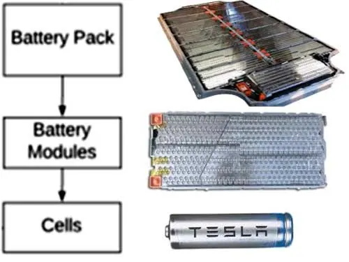
●Module
A module is an assembly of battery cells put in a frame by combining a fixed number of cells to protect them from external factors like heat, shock, or vibrations. Modules are welded together to complete the electrical current flow path within an EV. These modules can also incorporate temperatures and cooling mechanisms and monitoring of the voltage produced by each battery cell.
The Tesla Model S multiple 18650 cells to make the battery pack. But rather than arranging all the cells and making a single big battery, Tesla uses multiple smaller batteries called the battery module to make the final battery pack.
Each module has a 6S 74P configuration, i.e. 6 cells are connected in series and each of these series has 74 cells connected in parallel. Each of Tesla’s modules is rated for 500A of continuous current with 750Amps of peak current. There’s a liquid cooling integrated in order to maintain the temperature of the battery pack. The below image shows a single module of a Tesla Battery Pack.
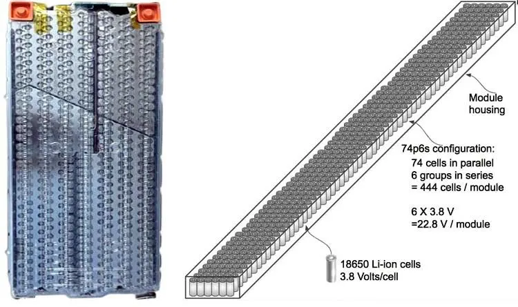
The left image shows the Tesla’s Model S battery module, while the right image shows how the battery is connected in a 6S 74P configuration. The pack has a configuration of 6S 74P and which makes the total number of cells as 444 cells. The total capacity of the battery module is 232 Ah and 5.3 kWh, to see how the series and parallel connection of the cell impacts its capacity and voltage check our previous article, designing a 12 volt battery pack. Tesla uses a wire bonding technique to connect each cell with the battery pack. The wire also acts as a safety fuse improving the safety of the overall system in case of a cell failure. The red circle in the below image shows how cells are connected using wire bonding.
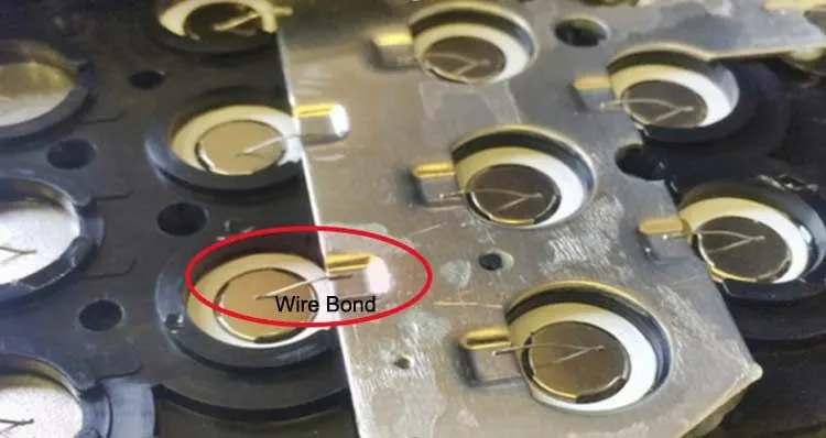
Advantages of Wire Bond Technique
- No heat is introduced to the cell during cell connection
- Wire act as a fuse
- If join fails, it doesn’t impact cells
- Improves manufacturability
Disadvantages of Wire Bond Technique
- Increases resistance due to additional wire
- It increases heat generation in the system
- Reducing operating efficiency
The specification of the battery module is given in the table below:
|
Parameter |
Specification |
|
Nominal voltage (Battery module) |
22.8V/Module |
|
Charge voltage cut-off(Battery module) |
25.2V/Module |
|
Discharging cut-off(Battery module) |
19.8/Module |
|
Maximum Discharging Current (10 sec.) |
750 Amps |
|
Height |
3.1 inch |
|
Width |
11.9 inch |
|
Length |
26.2 inch |
|
Weight |
55pounds |
Module’s Thermal Management
Li-ion cells are prone to heating under load and run the risk of a thermal runaway at high temperatures. The thermal runaway can increase the risk of fire hazards in a cell and subsequently initiate a chain reaction, thus, making the Li-ion battery pack and the EV unsafe to drive. The Thermal Management System is a very prominent safety feature that ensures that the temperature of the battery pack remains under a certain threshold by removing the heat from inside the battery pack. The below image shows the heat exchanger pipe which carries the cooling liquid inside the module.
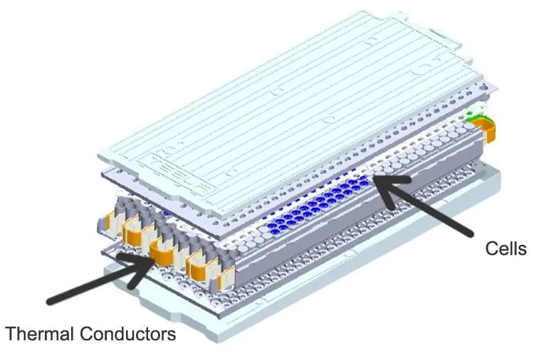
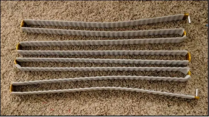
The cooling pipe is covered in thermally conductive and electrically insulative material which moderates the temperature inside the module while also isolating the cells from each other. At the bends, an orange insulating tape is used, this material is called Kapton tape and is used to improve the insulation. The coolant used in a Tesla’s battery pack is a solution of Water and glycol. The image below shows how the temperature of the solution increases as it flows through the battery pack.
●Pack
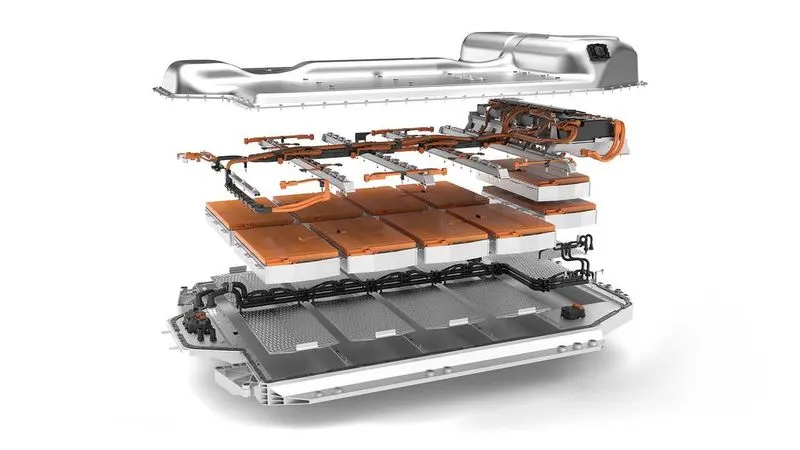
A pack is the final shape of an EV battery. It is composed of modules and various control systems, including the Battery Management System, thermal management system, etc.; these control systems are responsible for communications with the vehicle outside the battery pack.
The battery pack of Tesla model S also acts as a structural member and is placed at the underbelly of the car. It works as a foundation to the vehicle and provides rigidity and strength to the car and due to the positioning of such large weight in the lower part of the vehicle brings down the Center of Gravity of the car lower, thus increasing the balance and stability of the vehicle. The below image taken from the EV Tech Explained shows the structure of the empty battery pack.
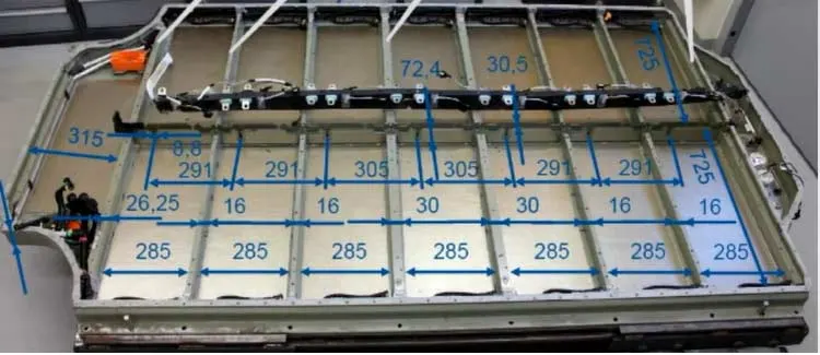
A total of 16 batteries can fit inside the base. Each niche accommodates a single battery module. The longitudinal members strengthen the chassis and provide resistance against longitudinal impact and side bending while the strength for the side is provided with the thick side members as they also provide protection against side impact. The internal members are used for making a grid for module placement but they also increase the strength and physical stiffness of the base while also isolating modules from each other in case of fires. The below image shows the placement of all 16 modules. On the right, the graphical illustration shows how the modules are connected with each other.
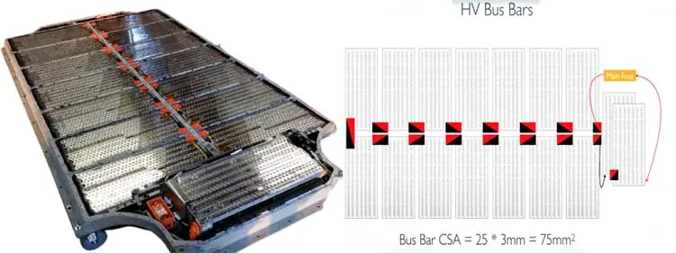
The HV bus bar is connected in the above orientation. The red points depict a positive connection while the black depicts the negative side of the connection in the battery pack. Busbars used in the battery pack are thick copper-coated tin plates.
An EV battery pack should be reliable and address issues that relate to impact resistance, thermal stability, and vibration isolation. While packaging a battery pack, there should be minimized mechanical and thermal interactions between the different units of a battery pack system to reduce the probability of the battery failing. There are critical factors and systems within a battery that have to be considered during packaging. These include the battery cell, gas exhaust nozzles, cell spacer type, insulation coating thickness, and the battery cooling system. These factors are crucial as they are the systems that make an EV operate safely and efficiently.
Enclosures:
The complete customization of a battery pack plastic enclosures is available right down to the plastic grade itself. It is important to understand what type of environment the application will be primarily used in and whether it will be used in extreme or mild conditions. The plastic grade will have to be selected to accommodate the appropriate environment. ABS plastic for an example is less expensive however it becomes very brittle when exposed to certain cold temperatures. There are a lot of plastic grades available and in some cases it is possible to create a Hybrid grade.
After the internal components have been secured, the enclosure has to be sealed. Take note that sealing the enclosure is part of the final assembly. Ultrasonic wielding is a method that uses high-frequency acoustic vibrations to generate heat. The heat melts the material voiding any need for screws or bolts.
Ultrasonic wielding is a robust and economically sound solution. Using screws or bolts are still a viable option. However, having access to surface screws or bolts may be good for repair but also easy access for end users to alter the application. Lastly, glue is another adequate sealing solution, typically used in lower quantities.
Concerns with internal components shifting during use have options to ensure parts stay in place. The actual product and how it will be used, handled, and stored determines how the enclosure will be created. Once there is an understanding on the actual product details, the enclosure would be designed internally. Procedures for securing internal parts include RTVs, designing ribs, combination of glues, and in most cases foam spacing - all of which help hold parts in place and minimize any shifting.
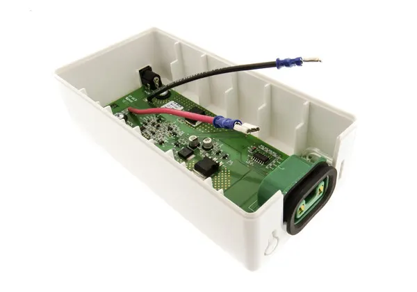
lithium batteries installed in a battery enclosure are required to have a safety PCB (Printed circuit boards) connected due to the transportation certification. In some cases anickel hydride battery will have a safety circuit installed. The basic functionality of having a safety circuit in place is to protect the battery from overcharging, short circuiting, over-discharging, and cell balancing.
If there are multiple battery cells within a battery pack, they need to operate in sequence. If the cells don't function in sequence they will continue to drift out of balance – ultimately causing expediential reduced battery cycle life.
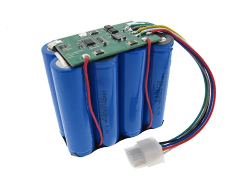
Figure: Lithium battery pack with safety circuitry.
Calculating the mechanical design parameters for the battery pack capacity of 18kWh
Cell Specifications: ANR26650M1-B
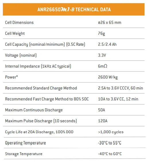
Cell Calculations:
Nominal voltage (Vc) = 3.3V
Nominal cell capacity (Cc) = 2.5A
Cell energy = nominal voltage * cell capacity
= 3.3 * 2.5
= 8.25 wh
Cell energy density = cell energy / cell volume
= 8.25 / 0.0003
= 27.5 kwh/ m^3
Battery voltage (Vb) = 240 V
Total number of cells
ct = sc * pc
where,
Sc = cells in series combination
Pc = cells in parallel combination
ct = total cells
Sc = vb/ vc
= 240 / 3.3
= 73 cells
Pc = Cb/Cc
Cb = battery capacity
= 18000/240
= 75 Ah/hr
Pc = 75 / 2.5
= 30 cells
Ct = total no. of cells
= Sc * Pc
= 73 * 30
= 2190 cell required
Battery pack is 73S30P
Total cell volume = Cell volume * total no. of cells
= 0.000034 * 2190
= 0.0744 m^3
Energy density = Battery pack energy / volume
= 18/ 0.0744
= 241.74 Kwh/m^3
Weight = Total number of cells * cell weight
= 2190 * 76
= 166440 grams
Weight = 164 kg.
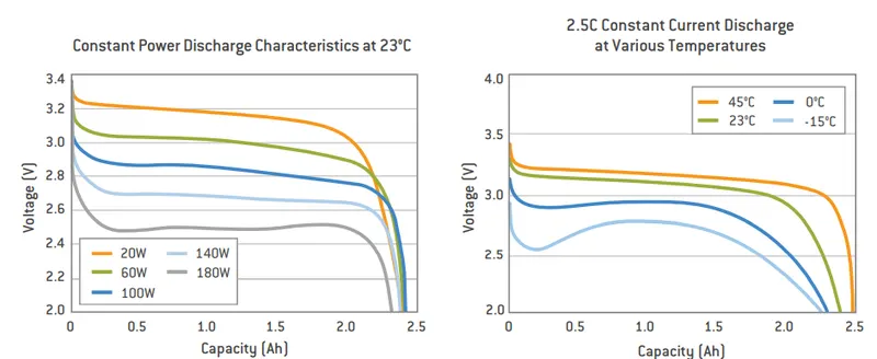
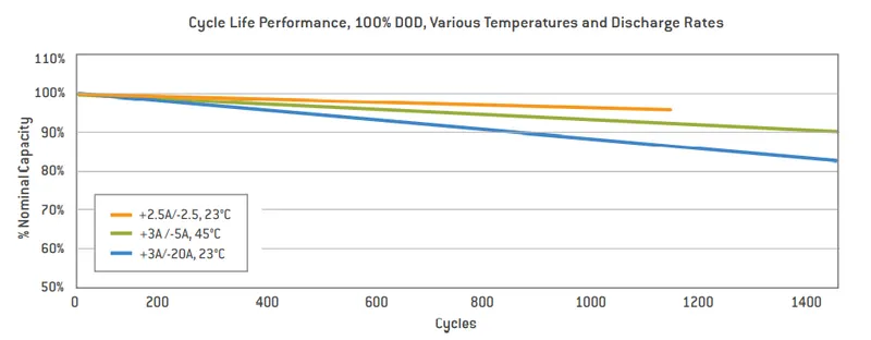
Plot Cell:
Applications:
COMMERCIAL SOLUTIONS
Advanced lead acid replacement batteries for:
1. Datacenter UPS
2.Telecom backup
3.IT backup
4.Autonomously guided vehicles (AGVs)
5. Industrial robotics and material handling equipment
GOVERNMENT SOLUTIONS
1. Military vehicles
2. Military power grids
3.Soldier power
4. Directed energy.