Week -2
AIM:
To make a simulink model of doorell using solenoid block.
SOLENOID:
A solenoid is a type of electromagnet. In electromagnet technology, a solenoid is a actuator assembly with a sliding ferromagnetic plunger inside the coil.Without power, the plunger extends for part of its length outside the coil; applying power pulls the plunger into the coil. Electromagnets with fixed cores are not considered solenoids. In simple terms, a solenoid converts electrical energy into mechanical work. The helix generates a controlled magnetic field. The coil can produce a uniform magnetic field in a volume of space when a electric current passed through it. Such solenoids provide magnetic focusing of electrons in vaccums, notably in television camera tubes such as vidicons and image orthicons. Electrons take helical paths within the magnetic fields. These solenoids focus coils, focus coils, surround nearly the whole length of the tube. The term solenoid was coined in 1823 by Andre-marie ampere to designate a helical coil. In the study of electromagnetism, a solenoid is a coil whose length is substantially greater than its diameter. The helical coil of a solenoid does not necessaarily need to revolve around a straight-line axis, for example william sturgeon's electromagnet of 1824 consisted of a solenoid bent into a horseshoe shape. In term solenoid also often reffers to a solenoid valve, integrating device containing an electromechanical solnenoid which actuates either a penumatic or hydraulic valve or a solenoid switch, which is specific type of relay that internally uses an electromechanical solenoid to operate an electric switch, for example, an automatic stater solenoid or linear solenoid. solenoid bolts, a type of electromechanical locking mechanism.
The simple doorbell circuit is:
GIVEN CONDITION: In the arrangement, when the switch is closed the electromagnet receives electric power from the battery and pulls the metal arm to hit the bell producing sound by creaing a situation where the switch is closed by 2 secs and then realesed.
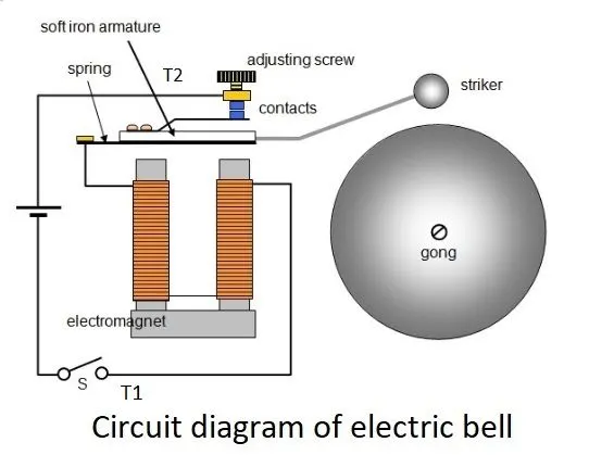
The following block in the model:
1. pulse generator
2. solenoid
3. scope
4. simulink-ps converter
5. ps-simulink converter
6. switch
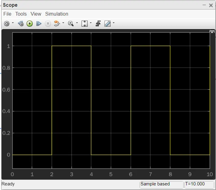
7. battery
8. electrical reference block
9. solver configuration
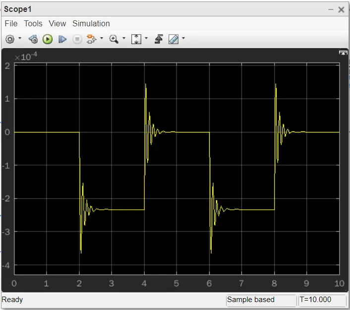
10. mechanical translation reference block
11. ideal translation motion sensor block
SIMULINK MODEL:
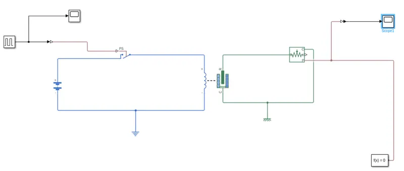
EXPLANATION:
1. From the above circuit of a doorbell, we know that we need a switch,battery,solenoid and plunger.
2. The connection of solenoid is connected across the switch,battery and electrical reference model.
3. The pulse generator is connected to switch through simulink to physical signal converter, to provide physical signal should be greater than the threshold of the switch for switch begin close or else it will be open.
4.The electrical reference block is connected to negetive side of the battery and to solenoid.
5. Electrical reference block is a earthing of the circuit.
6. Pulse generator block is connected to a scope to view the output graph.
7. The ideal translation motion sensor block is connected across the solenoid block.
8. In ideal translation motion sensor block the output are given as V and P which represent the velocity and position of the plunger. Now we are interested in change of position of the plunger, so we are taking the output of P.
9. The ideal translation motion sensor block of R terminal is connected to R terminal of the solenoid and the C terminal is connected C terminal of the solenoid through mechanical translation reference.
10. The P terminal of the ideal translation motion sensor block is connected to physical signal to simulink converter and that to a scope to run the output result.
11. The P terminal of the ideal translation motion sensor block is also connected to a slover configuration.
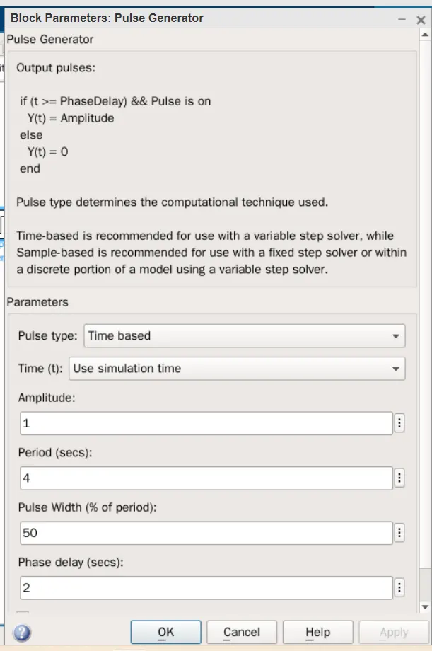
12. The pulse generator period value is 4 secs and the pulse width is 50% and phase delay is 2 secs and the amplitude is by default 1 we have not change it.
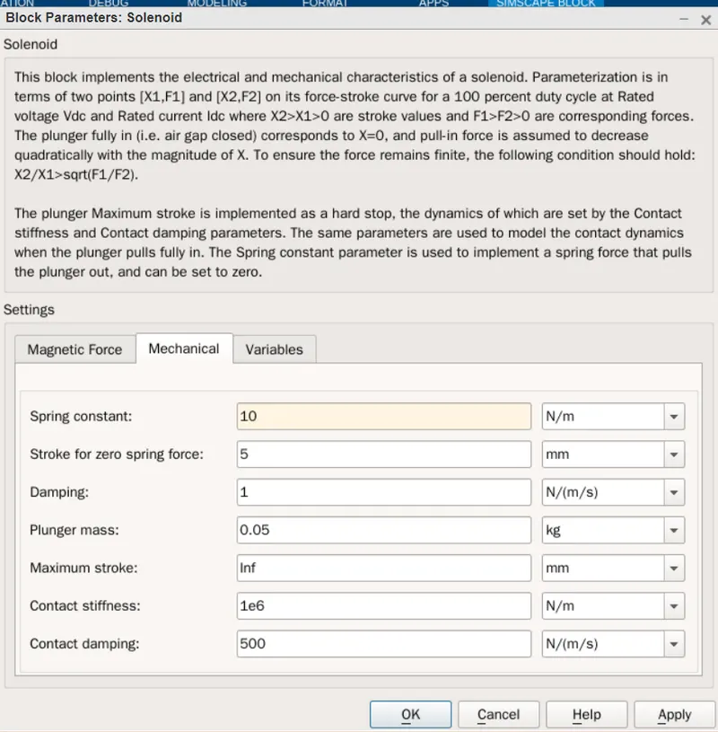
13. In the above figure is a smoother graph. This was done by changing the value of spring constant and damping coefficient in the solenoid block.
14. To this pulse generator a scope block is connected to see how the pulse is generated.
15. By double clicking the scope block the pulse is generated in the graph. The x-axis is the time and the y-axis is the amplitude. The pulse is generated as shown in above figure. The time period of pulse is 2secs.
16. Since the pulse that is coming from pluse genereted block is a simulink value, so to convert this value into physical value we have used the simulink-PS converter block, Since switch only take physical value as input.
17. The above shown figure is scope block1 which is connected from ideal translation motion sensor through PS-Simulink converter.
18.The ideal translation motion sensor block in that P is connected to scope to get the result. The P is also connected to the slover configuration this path generates the equation and solves the whole model internally to give the results of the whole simulink model output.
19.Now run the model and double click on the scope block1 which is connected to the ideal translation motion sensor block to get the result.
20. we will get the above graph that shows X-axis is represents the time and Y-axis is represents the amplitude of the plunger in mm.
21. The amplitude of pulse become zero, the plunger returns to the original position back again and as the pulse cycle goes on, plunger is also at same position after the change from initial position.
22. The simulink model of doorbell using solenoid block is obtained.
CONCLUSION:
The physicial movement of plunger of solenoid was observerd when switch is closed for 2 secs.
Simulink particularly helps to improve the performance by analyzing it on plot and changing the suitable configuration, as in above case of solenoid operated bell spring constant and damping was varied as shown above.
2. AIM: To create a simulink model of a thermister to sense the temperature of a heater and turn on and turn off the fan.
CONDITION: Temperature source: 20°c from 0 to 10 seconds, 27°c from 10 to 30 seconds, 23°c from 30 to 50 seconds
Fan conditions: ON if the temperature above 25°c, OFF otherwise.
BLOCKS USED IN THE MODEL:
1. switch
2. scope
3.Thermistor
4. Resistor
5. Battery
6. Voltage source
7. Display
8. Repeating sequence stair
9. Controlled temperature source
10. Lamp
11. Solver configuration
12. PS-Simulink converter
13. Simulink-PS converter
SIMULINK MODEL:
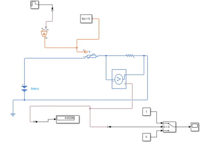
MODEL EXPLANATION:
A repeating sequence stair is given as input to the thermistor through a controlled temperature source. The definition of repeating sequence stair is shown in below.
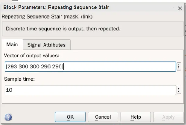
The condition of the temperature source is defined inside the above window. The sample time was taken as 10sec.
The battery and resistor is connected to the thermistor circuit. The resistance of resistor can be set to any value. The voltage sensor was connected to the across the resistor to measure the voltage change during different temperatures. The threshold temperature was given as 25 degree celsius and the corresponding the voltage over the resistor was found out, through a display connected to the voltage sensor. At this time the repeating sequence stair given only one value that is 25 degree celsius or 298k. The output from the voltage was also given into a switch which is given to lamp which displays different colours based on logical condition. The lamp colour was set to change if the temperature was below 298k and also changes if the temperature was above 298k.
CONCLUSION:
The simulink model of a thermistor to sence the temperature of a heater and turn on and off the fan, temperature source and fan condition is obtained by the above simulink model.