Project 1 Mechanical design of battery pack
Battery pack capacity: 18 kWh
Cell: ANR26650M1-B
Prepare a detailed battery pack drawing along with its enclosure. State your assumptions.
Objective: For the cell model of ANR2665031-B,
- To calculate the all necessary parameters required to design a battery pack.
- To make a report of all calculated parameters.
- To prepare a detailed battery pack drawing along with its enclosure.
The cell which is given for the design of battery pack is designed and manufactured by A123 systems. It is a high performance Nanophasphate Lithium iron phosphate (LiFePO4) battery technology which delivers high power and energy density combined with excellent safety performance and extensive life cycling in a lighter weight, more compact package. The cells manufactured by this company have low capacity loss and impedence growth over time as well as high usable enrgy over a wide SOC range, allowing our systems to meet end of life power and energy requirements with minimal pack oversizing.
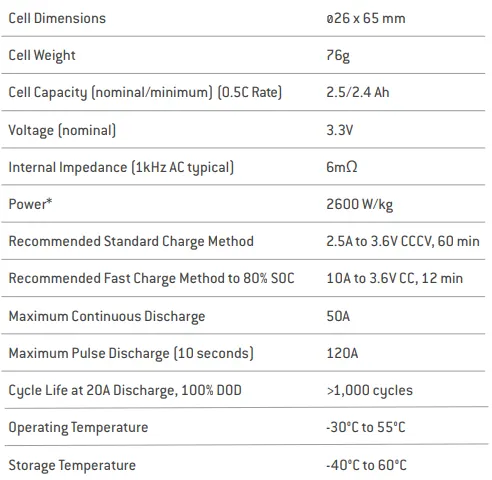
To calculate all the parameters, we need the data of the cell ANR2665031-B, for that we have to check the datsheet of the cell. The following figure shows the basic charactersitics of the cell given in its datasheet.
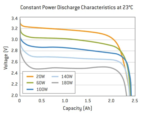
The following are the constant power discharge characteristics of the cell at 23°C temperature. This characteristics are drawn for different power ratings of the cell. If we observe the plot, as the power of the cell increases the voltage and its discharging characteristics are decreasing.
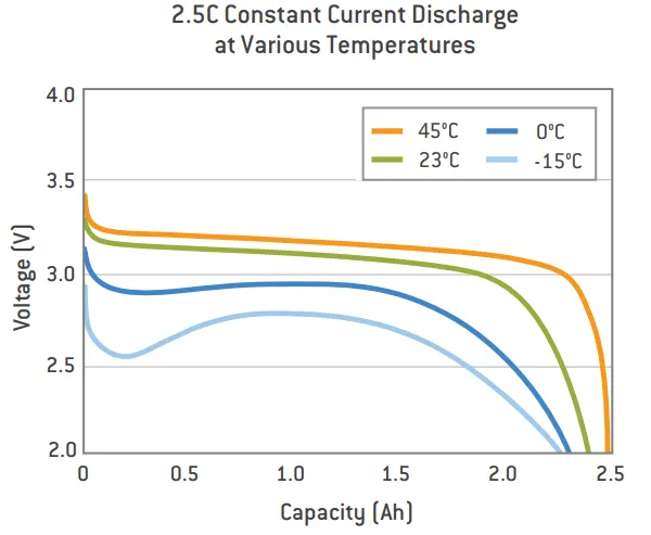
The following figure shows the 2.5C rate Constant current discharge charactersistics at different temperatures, If we observe the plot it can be say that, the cell characteristics are varies with respect to the temperature changes. So we have to operate the cells within its nomial temperature zone.
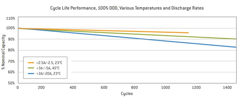
The following figure shows the cycle life performance, 100% DOD (Depth Of Discharge), various temperatures and discharge rates of the cell.
The battery parameters have a significant influence on other components and atributes of the vehicle, like: Maximum traction motor torque, Maximum regeneration brake torque, Vehicle range, Vehicle total weight, Vehicle price. So based on all these parameters we have to design a battery pack. All major aspects of a pure electric vehicle depend on the parameters of the high voltage battery.
A battery pack consists of one or moe electrochemical cells which are converting chemical energy into electrical energy during discharging and electricall energy into chemical energy during charging. There are several types of batteries used in hybrid and electric vehicle propulsion systems but we are going to consider only Lithium-ion cells. The main reason is that Li-ion batteries have higher specific energy (Wh/kg) and specific power (W/kg) compared with other types. The following plot shows the Ragone chart of different cells. The Li-ion shows its best characteristics compared to other cells.

The voltage level of the battery determines the maximum electrical power which can be delivered continuously. As power is the product of voltage and current. The higher the current, te bigger the diameter of the high voltage wire and higher the thermal losses. For this reason the current should be limited to a maximum and the nomial power obtained by having a higher voltage. For our modelling of pack, considering the nominal voltage of 264V. All high voltage battery packs are made up from battery cells arranged in strings and modules. A battery cell can be regarded as the smallest divison of the voltage.
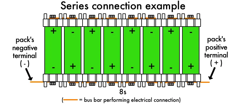
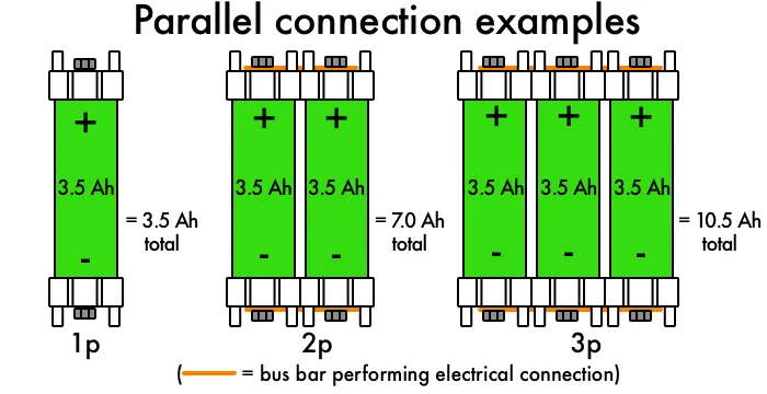
Individual battery cells may be grouped in parallel and/or series as modules. Further, battery modules can be connected in parallel and/or series to create a battery pack. Depending on the battery parameters there may be several vlevels of modularity. The total battery pack voltage is dertermined by the number of cells connected in series. The current capcity of the battery pack is determined by the number of cells connected in parallel. Following figures gives the information of series and parallel connections.
Based on the cell parameters provided by the manufacturers, we can calculate the energy content, volume, gravimetric density and volumetric density for each cell. The following figure shows the dimentions of the ANR2665031-B cell.
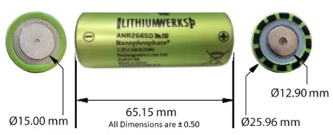
CALCULATION OF PARAMETERS: By using the data from the datsheet of ANR2665031-B cell, and by making the required assumptions the following parameters are caluculated.
From the datasheet, the following parameters are considered for the calculation.
Cell dimensions = 26mm×65mm (diameter of cell×height of cell)
Cell weight = 76g
Nominal cell capacity = 2.5Ah
Nominal voltage = 3.3V
Power = 2600W/kg
Continuous C-Rate = 10
Peak C-Rate = 24
Volume of Cell (For cylindrical) = πr²h
Radius of a cell = Diameter/2 = 26/2 = 13mm = 0.013m
Height of a cell = 65mm = 0.065m
Volume of a Cell = πr²h = 3.14×0.013²×0.065 = 3.45×10^-5 m³
Volume of Cell = 3.45×10^-5 m³
Now will calculate the energy of each cell,
Cell energy = Cel capacity × Cell voltage
Cell energy = 2.5 × 3.3 = 8.25
Cell Energy = 8.25Wh
Now we canculate total energy of cell by using each cell energy,
Battery pack energy density = Cell energy ÷ Volume of a cell
Battery energy = 8.25 ÷ 3.45×10^-5 = 239130.435
Battery pack energy density = 239130.435 Wh/m³.
Gravimetric Energy = Cell Energy ÷ Weight of cell
Weight of cell = 76g = 0.076kg
Gravimetric Energy = 8.25÷0.076 = 108.55
Gravimetric Energy = 108.55Wh/kg.
In our challenge we have to make a battery pack capacity of 18kWh = 18000Wh
Number of cells connected in series = Battery pack voltage ÷ Voltage of each battery cell
Let us assume the battery pack voltage required is 264V.
No. of cells connected in series = 264÷3.3 = 80
Number of cells connected in series = 80 cells.
Energy of a string = No. of cells connected in series × Energy of a battery pack
Energy of a string = 80×8.25 = 660
Energy of a string in series = 660Wh.
Number of cells connected in Parallel = Battery pack Capacity ÷ Energy of a string in series
No. of cells connected in Parallell = 18000÷660 = 27.27
Number of cells connected in Parallel = 28 cells.
Battery pack capacity = Number of cells connected in Parallel × Capacity of a cell
Battery pack capacity = 28×2.5 = 70
Battery pack capacity = 70Ah.
Total number of cells in a battery pack = Number of cells connected in series × Number of cells connected in Parallel
Total number of cells in a battery pack = 80×28 = 2240
Total number of cells in a battery pack = 2240 cells.
Weight of the battery pack = Total number of cells in a battery pack × Weight of a cell
Weight of the battery pack = 2240×0.076 = 170.24
Weight of the battery pack = 170.24kg.
Volume of the battery pack = Total number of cells in a battery pack × Volume of a cell
Volume of the battery pack = 2240×3.45×10^-5 = 0.07728
Volume of the battery pack = 0.07728 m³.
String peak current = Peak C-Rate of a cell × Cell capacity
String peak current = 24×2.5 = 60
String peak current = 60A.
Battery pack peak current = String peak current × Number of cells connected in Parallel
Battery pack peak current = 60×28 = 1680
Battery pack peak current = 1680A.
Battery pack Peak power = Battery pack peak current × Battery pack voltage
Battery pack Peak power = 1680×264 = 443520W = 443.5kW
Battery pack Peak power = 443.5kW.
String continuous current = Continuous C-Rate of a cell × Capacity oof a cell
String continuous current = 10×2.5 = 25
String continuous current = 25A.
Battery pack continuous current = String continuous current × Number of cells connected in Parallel
Battery pack continuous current = 25×28 = 700
Battery pack continuous current = 700A.
Battery pack continuous power = Battery pack continuous current × Battery pack voltage
Battery pack continuous power = 700×264 = 182700W = 182.7kW
Battery pack continuous power = 182.7kW.
Report of Calculated parameters: All calculated parameters all listed below in the table.
| Parameter Name | Parameter Value |
| Volume of Cell | 3.45×10^-5 m³ |
| Volume of the battery pack | 0.07728 m³ |
| Weight of the battery pack | 170.24kg |
| Cell Energy | 8.25Wh |
| Battery pack energy density | 239130.435 Wh/m³ |
| Gravimetric Energy | 108.55Wh/kg |
| Number of cells connected in series | 80 cells |
| Number of cells connected in Parallel | 28 cells |
| Energy of a string in series | 660Wh |
| Battery pack capacity | 70Ah |
| Total number of cells in a battery pack | 2240cells |
| String peak current | 60A |
| Battery pack peak current | 1680A |
| Battery pack Peak power | 443.5kW |
| String continuous current | 25A |
| Battery pack continuous current | 700A |
| Battery pack continuous power | 182.7kW |
Before moving to the enclosure procedure we have to know the few steps for making a battery pack that is Cell → Battery module → Battery pack.
- Battery cell is basic unit of a Li-ion battery that exerts electric energy by charging and discharging. Made by inserting cathode, anode, seperator and electrolyte into a rectangular aluminium case.
- Battery module is a battery assembly put into a frame by combining a fixed umber of cells to protect the cells from external shocks, heat or vibration.
- Battery pack is the final shape of the battery system installed to an electric vehicle. Composed of modules and various control/protection systems including a BMS (Battery Management System), a cooling system etc.
ENCLOSURE PROCEDURE:
The number of cells are connected in series or parallel according to the battery capacity. After making the required connections we have to assemble the cells in the holders. The cell holder normally consists of a hollow cylindrical brass block with an outside diameter of 50-80mm and an inside diameter of 10-20mm, which matches the ouside diameter of the scattering cell. These battery holders are designed to maximize the packaging density of an battery pack. That means we can fit more cells into less space, while still maintaining air gaps between cells. The following figure shows the holding of different battery cells according to their connection type(series and parallel).
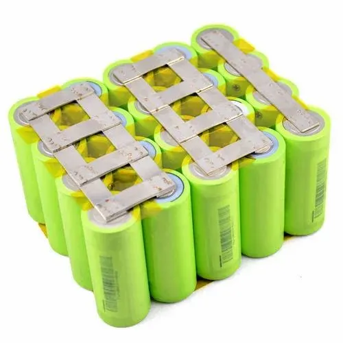
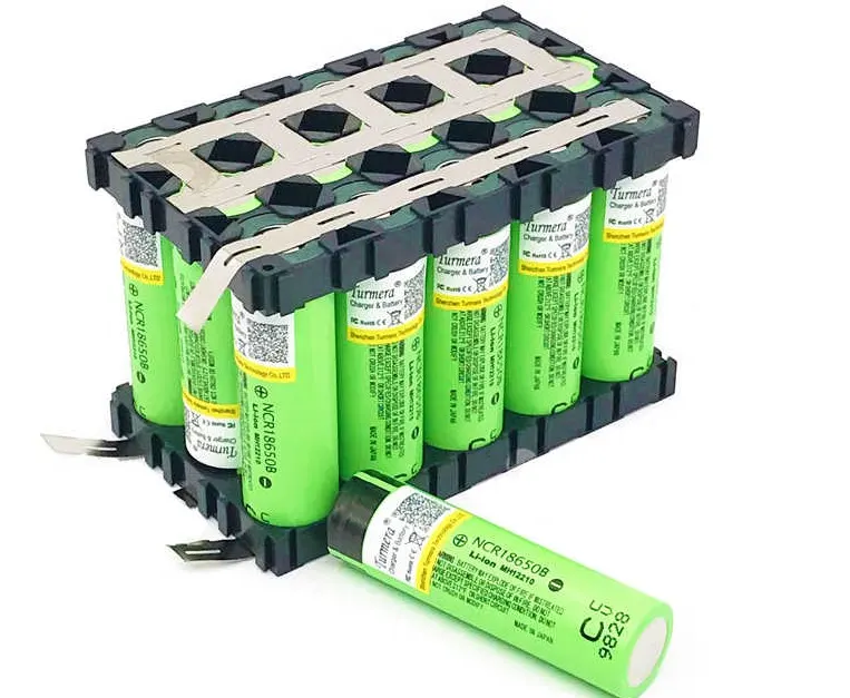
By using the Nickle strips will connect the cells in parallel or series as per our capacity and voltage requirements. Nickle strip is generally used in battery building. Its due to its efficiency of usage in spot welding and soldering as well as its high corrosion resistance over time. It has good properties and excellent resistance to many corrosive environments. The following figure shows that how the nickle strips are connected to the battery cells. If both ends are connected it is parallel connections and if only oe ends are connected it is series connection, we can observe this in the below image. The second image shows the holders with the connection made by using nickle strips.
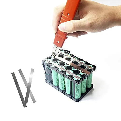
To connect the Nickle strips will use spot welding technique. Spot welding works by applying pressure and heat to the weld area using copper alloy electrodes. These electrodes transport an electrical current through the weld segments. As the material melts the parts are fused. At this point, the current is turned off and pressure from the elctrodes is upheld. This can be done through manually or by using machinery. The following figure shows the spot welding of the battery cells.
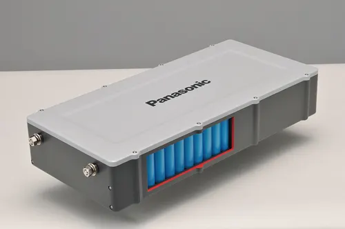
Now we have to make the group of cells connected together into a module. The battery module means a set of battery cells that are connected together or encapsulated within an outer casing to protect the cells against external impact, and wich is meant to be used either stand alone or combination with other modules. For the purpose of this regulation, a battery module that is place on the market ready to be used or to be assembled has to be considered as a battery. The following figure shows the arrangement of battery cells inside of battery module.
Module Testing: In this stage we test all modules individually to measure the capacity and wuality of each module. BMS contains common circuitary as well as discrete circuitry and plays a vital role in managing the cut off of the battery pack while charging, discharging, over temeprature, low temperature, short circuit conditions. This circuitry also balances the strings of the battery pack. BMS tester machine is used to check the every BMS fuction. Around 35such parameters are checked in this process.
BMS and Power Wiring: Checking each string of cells in the module before and after conecting in series is very important. Next, we will connect the BMS control wires into the battery pack in order. Battery pack positive terminal is directly connected to the output. BMS negative and Battery pack negative will connect to the battery pack. The following figure shows the connection of BMS.
Assembly: In this stage we connect the BMS, assemble the packs check the sensing voltages and all connections by quality check using a multimeter. If any of the battery pack's strings and modules show irregularities in the expected voltage, resistance or capacity range, it can be found here and rectified. After wiring the semi finished battery pack, we go for capacity testing using the indivisual battery capacity testing machine.
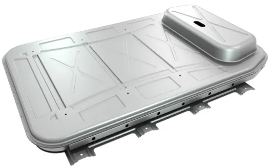
Using an advanced computer software, each process will be programmed before connecting the machine with semi finished battery pack. Here we observe and compare the final outcome of the battery pack with what we expected from the very beginning: checking the malfunction, temeperature rise in the battery pack, capacity, steady current flow, current carrying capacity of the nickle strip and power cable etc. After this process, the battery pack will go for final completion of casing and then to finished goods area. The following figure shows the completely finished battery module.
This battery modules are further used for different applications. We can connect number of modules according to the requirement of capacity. The following figure shows the diagram of multi module pack, which consists of battery modules, cooling system, BMS, housing and interfaces etc.
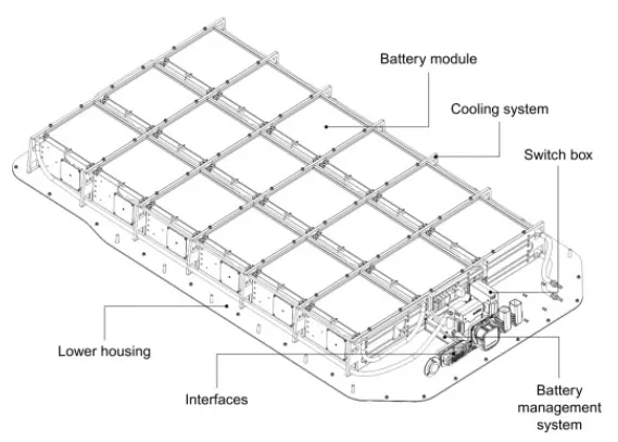
In the following figure we can see the arrangement of modules in an Electric vehicle. In this will model the battery pack and perform few tests to check all the parameters and physical characteristics of the number of cells and modules.
Conclusion: For the given cell model of ANR2665031-B, we have calculated all the parameters required to make a battery pack. The parameters which are calculated has ben tabulated. And the enclosure procedure is also explained with the respective figures