Project 1 Mechanical design of battery pack
Aim: To design a battery pack with the help of ANR26650M1-B cell.
Study:
What is a cell?
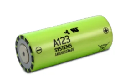
A cell is the smallest unit of a battery, comprised of 4 key components including cathode, anode, electrolyte and separator. The characteristics of a battery cell play a pivotal role in the overall performance of electrified vehicles.
What is battery?
An electric battery is a source of electric power consisting of one or more electrochemical cells with external connections for powering electrical devices.
When a battery is supplying power, its positive terminal is the cathode and its negative terminal is the anode. The terminal marked negative is the source of electrons that will flow through an external electric circuit to the positive terminal. When a battery is connected to an external electric load, a redox reaction converts high-energy reactants to lower-energy products, and the free-energy difference is delivered to the external circuit as electrical energy
Now for the Cell ANR26650M1-B:
A123’s high-performance Nanophosphate® lithium iron phosphate (LiFePO4) battery technology delivers high power and energy density combined with excellent safety performance and extensive life cycling in a lighter weight, more compact package. Our cells have low capacity loss and impedance growth over time as well as high usable energy over a wide state of charge (SOC) range, allowing our systems to meet end-of-life power and energy requirements with minimal pack oversizing.
This cell is used in many different applications such as:
- COMMERCIAL SOLUTIONS
- Advanced lead acid replacement batteries for:
+ Datacenter UPS
+Telecom backup
+IT backup
+Autonomously guided vehicles (AGVs)
+ Industrial robotics and material handling equipment
- GOVERNMENT SOLUTIONS
+ Military vehicles
+ Military power grids
+Soldier power
+ Directed energy
- GRID SOLUTIONS
+ Frequency regulation
+ Renewables integration
+ Reserve capacity
+ Transmission and distribution
- TRANSPORTATION SOLUTIONS
- Hybrid, plug-in hybrid and electric vehicle battery systems for: +Commercial vehicles
+ Off-highway vehicles
+Passenger vehicles
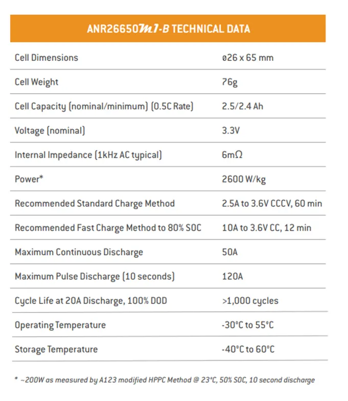
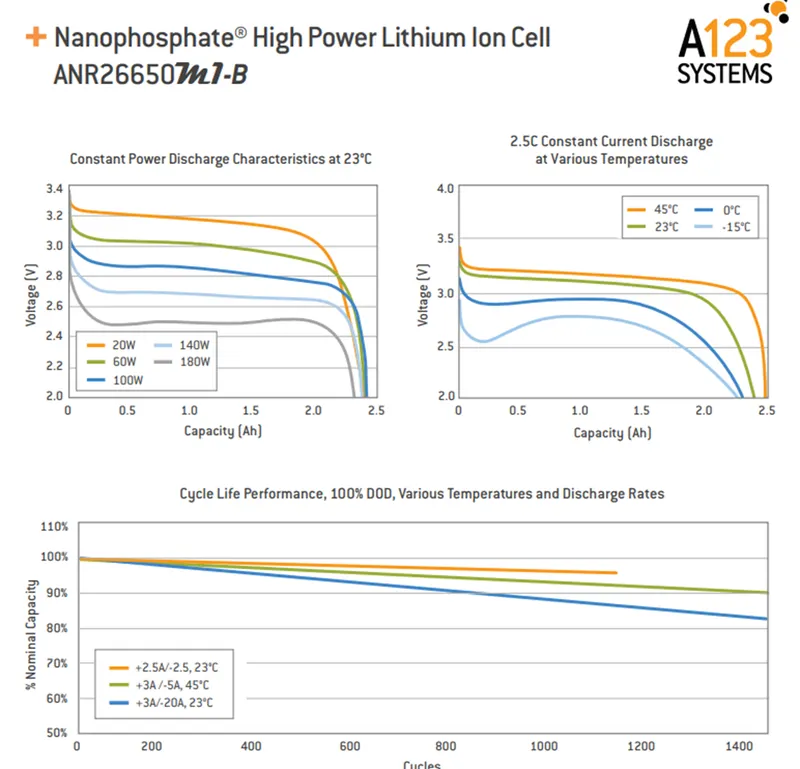
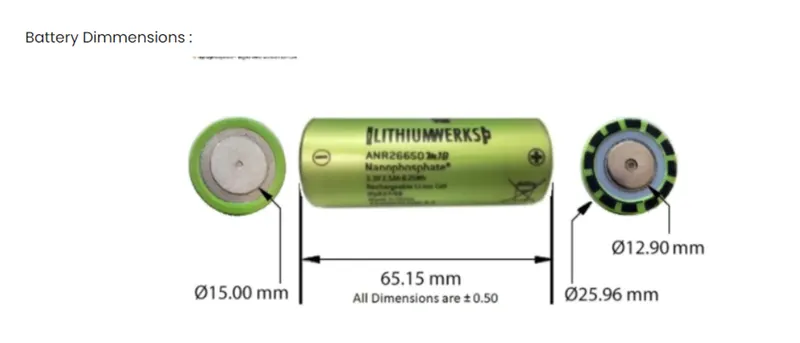
The specifications of this cells are given as follows:
Now to design a battery pack of 18kW with this cell, we take a combination of 80S and 30P.
For a single cell,
Nominal voltage = 3.3V
Nominal current = 2.4Ah
Capacity of a single cell = 3.3*2.5 = 7.92V
For 80 series = 80 * 3.3 = 264Vign
For 30 parallel = 30 * 2.4 = 72Ah
Capacity = 264 * 72 = 19.008kWh
Design overview:
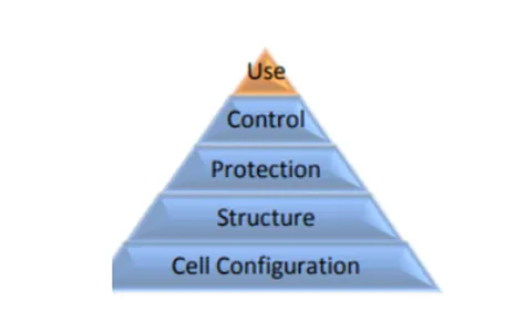
A battery pack is a system of multiple components and functions and its design involves the application of knowledge and practice in the electrochemical, electrical, mechanical, thermodynamic and control fields. The followings sections summarize the various stages of a battery pack design, covering specific aspects of A123 cells which may be unique from the other cells.
- The first step in the design of the pack is to determine the configuration of cells, i.e. how many cells overall, how many are in series and in parallel.
- The second step is to design a mechanical structure around the cells to support and protect them.
- The third step is to design the protection of the cells, particularly electrical protection. The pack must be protected from the short circuits internal and external to the packs.
- The fourth step is the design the Battery management system for the battery that manages and monitors the cells.
- Finally, a pack performs best when it is used properly.
Mechanical connections:
Design mechanical connects so that it prevents the short circuits among the cells. The circuits ae expected to carry the rated current and even the double of the rated current for a short amount of time.
Cell interconnects:
A123 systems recommends either pure nickel tabs or nickel-clad copper tabs. In addition, other alloys afford both weildability strength and low resistance which are desirable function for a good connection.
Gaps:
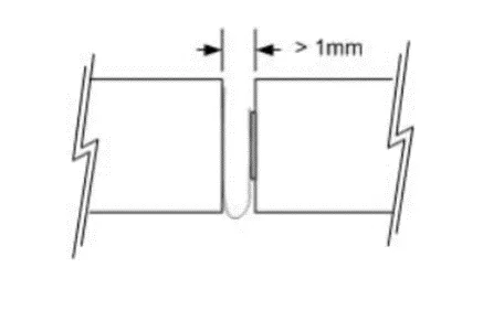
The cell vent located on the end caps of the cells should not be blocked by any mechanical means. Blocking the cells vents and abusing the cell so as to build up the pressure in the cell prevents the cell from properly venting. An ESS designed to installed cells end-to-end needs atleast 1mm of space between the cells to allow venting.
Series Strings:
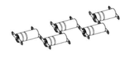
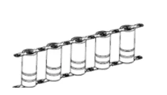
Cells combined in series strings can achieve higher operating capabilities by connecting like polarity terminals of the adjacent cells to each other. Connect strings of series connected cells using their current collection tabs in a manner similar to that illustrated in the figure.
Parallel Strings:
Cells combined in parallel strings can achieve higher operating capabilities by connecting like polarity terminals of the adjacent cells to each other. Connect strings of parallel connected cells using their current collection tabs in a manner similar to that illustrated in the figure.
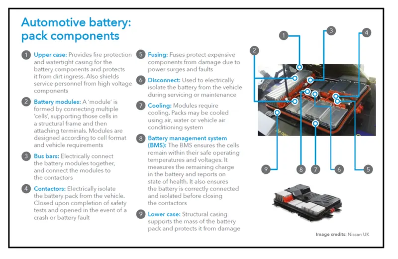
Components of Automotive battery packs: