Project 1 Mechanical design of battery pack
Aim: To Prepare a battery back with the given cell having a power capacity of 18kWh.
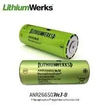
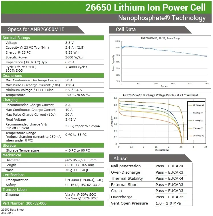
Here are the details of the Cell
ANR26650M1-B
Step 1: Determining the number of cells required
From the data sheet, we can see that the capacity of one cell is 8.25 Wh.
Therefore, In order to have battery capacity of 18kWh we will need `18000/8.25~~2182`
Assuming This car to be a Hybrid ELectric Vehicle:
The voltage level required by it will be 48V
In order to have 48V as battery output, we need the following number of cells in series:
No of series cells= Battery Pack voltage/Single cell voltage=`48/3.3=14.54~~15`
Hence we require 15 cells in series
So, the power capacity of one series leg will be 15*8.25Ah=123.75Wh
Therefore the number of parallel cells will be= `18000/123.75=145.45~~146`
Hence, total number of cells will be=15*146=2190
This number matches with our first step which was based on power requirements.
The battery pack will be 15S146P configuration
Step 2: Mining of Lithium
The light metal is generally found either in underground deposits of clay, in mineral ore or underground pockets of water. Commonly, extracting lithium from these deposits involves two methods. One is building a mine, extracting the clay or ore, and separating the metal through a complex process. The second is to pump underground water deposits to the surface. The resulting pools of briny liquid are left to evaporate, and lithium is removed from the dried salts that remain.
The first process has often involved displacing thousands of acres of dirt and rock (known as overburden material), disrupting nearby land and eradicating plant life. The second process may consume huge quantities of fresh water — often sourced from wells, streams or aquifers that are also used for farming or drinking water, itself a precious resource in the arid regions where lithium deposits are found.
In addition to environmental concerns there is the impact on local communities. Large earth-moving equipment has invaded quiet, out-of-the-way towns, and sprawling cattle farms have had new mountains of clay and dirt impede their livestock grazing area and water supply.
Step 3: Manufacturing
First, the active material (AM), conductive additive, and binder are mixed to form a uniform slurry with the solvent. For the cathode, N-methyl pyrrolidone (NMP) is normally used to dissolve the binder, polyvinylidene fluoride (PVDF), and for the anode, the styrene-butadiene rubber (SBR) binder is dissolved in water with carboxymethyl cellulose (CMC). The slurry is then pumped into a slot die, coated on both sides of the current collector (Al foil for cathode and Cu foil for the anode), and delivered to drying equipment to evaporate the solvent. The common organic solvent (NMP) for cathode slurry is toxic and has strict emission regulations. Thus a solvent recovery process is necessary for the cathode production during drying and the recovered NMP is reused in battery manufacturing with 20%–30% loss (Ahmed et al., 2016). For the water-based anode slurry, the harmless vapor can be exhausted to the ambient environment directly. The following calendering process can help adjust the physical properties (bonding, conductivity, density, porosity, etc.) of the electrodes. After all these processes, the finished electrodes are stamped and slitted to the required dimension to fit the cell design. The electrodes are then sent to the vacuum oven to remove the excess water. The moisture level of the electrodes will be checked after drying to ensure the side reaction and corrosion in the cell are minimized.
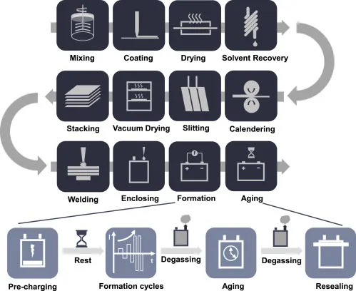
Figure 1. Schematic of LIB manufacturing processes
After the electrodes are well prepared, they are sent to the dry room with dried separators for cell production. The electrodes and separator are winded or stacked layer by layer to form the internal structure of a cell. The aluminum and copper tabs are welded on the cathode and anode current collector, respectively. The most common welding method is ultrasonic welding, and some manufacturers may choose resistance welding for their cell design. The cell stack is then transferred to the designed enclosure, which does not have a consistent standard currently. Each manufacturer has their preference depending on the purpose of the cells. The enclosure is filled with electrolyte before the final sealing and completes the cell production.
Before delivering the cells to the end product manufacturers, the electrochemistry activation steps are applied to these cells to enable operation stability. A stable solid-electrolyte interface (SEI) layer can prevent the irreversible consumption of electrolyte and protect the anode from overpotential during fast charging, which can result in forming Li dendrites (Li et al., 2019). The formation and aging process starts from charging the cells to a relatively low voltage (e.g., 1.5V) to protect the copper current collector from corrosion, followed by a rest session for electrolyte wetting. The cells are charged/discharged under a low rate such as C/20, and then the rate will be gradually increased to ensure a stable SEI layer on the surface of the anode (Wood et al., 2019). The gas generated from the formation process needs to be discharged for safety concerns. After or during formation cycles, the cells are stored on the aging shelves for complete electrolyte wetting and SEI stabilization. Another degassing step is arranged before the cells are finally sealed for future applications. Depending on the formation protocol and aging temperature, this step normally lasts several weeks.
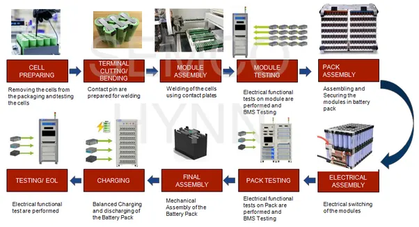
Step 4: Battery pack assembly
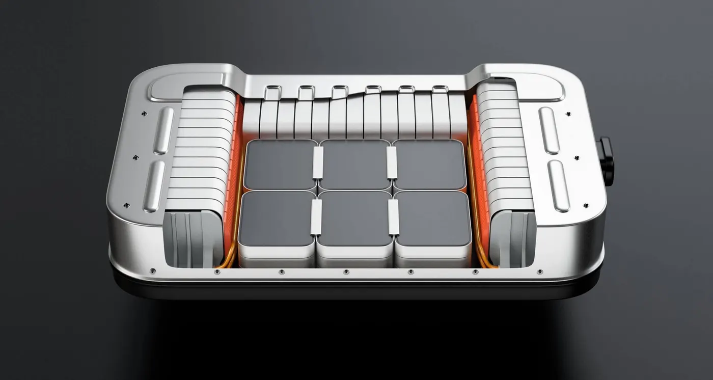
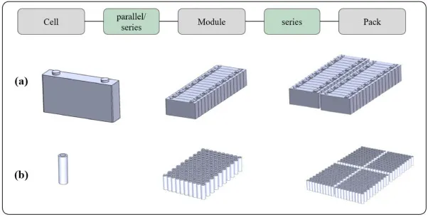
These battery cells are assembled together in frames to form Battery Modules. These modules are then linked together via a myriad of electrical connections and enclosed in the Battery Pack which is assembled directly to the automobile frame. The following arrow diagram below is a compass to understand the process terminology.
Battery Cells -> Battery Modules -> Battery Pack
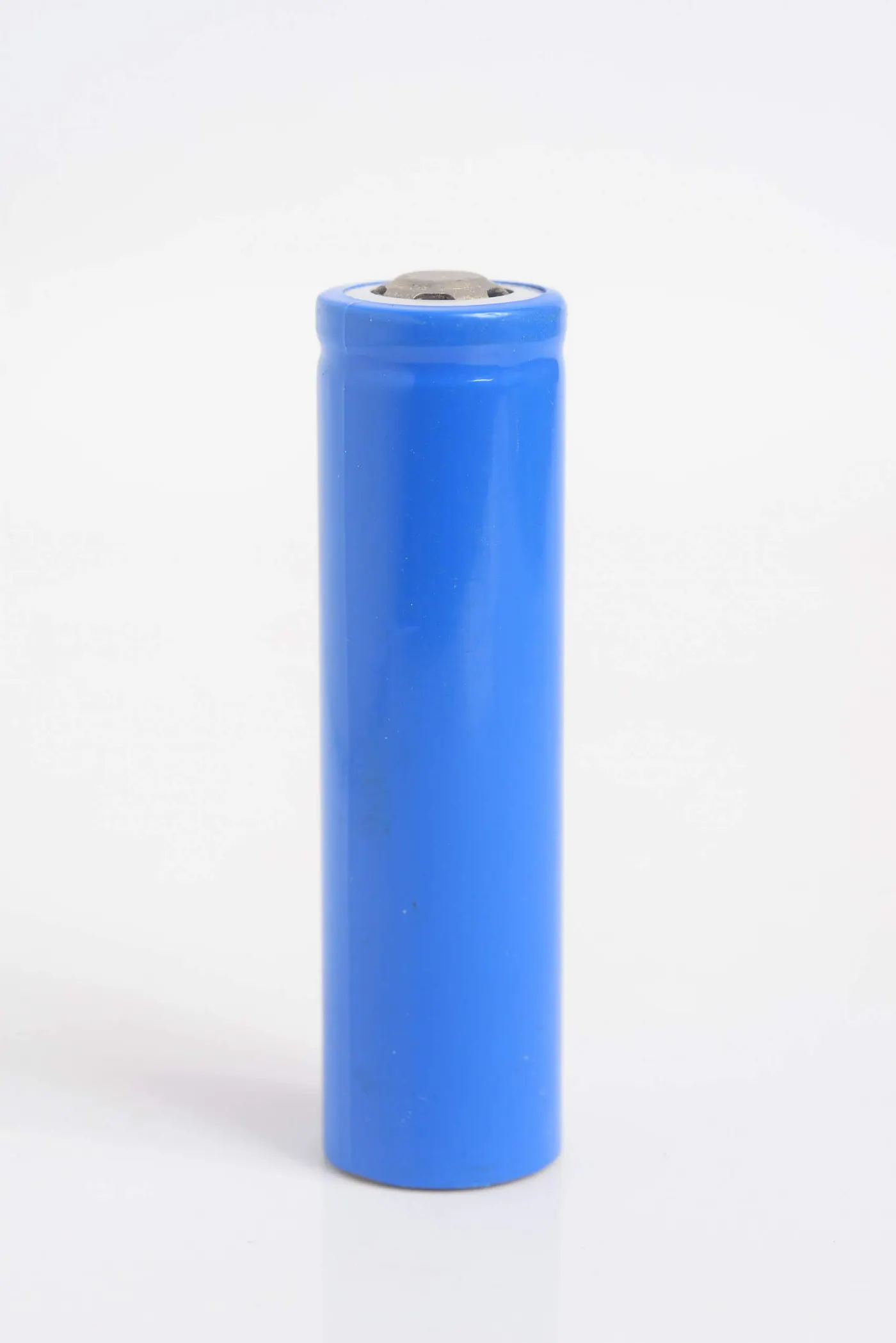
Battery Modules


Before the cells can be assembled into modules, each cell undergoes checks within a specialized fixture. This process is essentially a “leak check” process to ensure that the electrolyte isn’t leaking from the cell and to ensure that no moisture intrusion occurs over the entire operational life of the battery. This step is vitally important to ensure that the cells are properly functioning, and future battery capacity won’t be compromised.
The last step in battery pack fabrication is assembling the modules into the battery pack housing. This step involves a significant number of electrical hookups and fine-tuning. For example, the Nissan Leaf EV contains 48 battery modules which are all connected together via electrical monitoring equipment. These modules are typically picked and placed by an automated robotic assembly arm into the battery pack housing. After all the modules are placed into the housing they are manually connected together by an automotive technician. After all connections have been made, the battery pack housing cover is placed manually; finally, an automated robot arm is typically used to drill all screws thus completing the battery pack fabrication process.
Quality criteria
In order to assess the suitability of a joining technology for battery interconnections appropriately, it is necessary to deduce interdisciplinary requirements. Here, four categories can be defined in accordance with Das et al. (Das et al., 2018):
•Electrical and thermal requirements
○Resulting joints should have low electrical resistance with a narrow scattering range
○Thermal input during manufacturing should be as small possible
○High thermal fatigue resistance of created joints
•Material and metallurgical requirements
○Low corrosion risk
○Joining of dissimilar materials
○Adaptability to a variety of surface conditions and materials
•Mechanical requirements
○Strong interconnections
○Good fatigue and creep resistance
○Low pre-stress level
○Avoid mechanical or vibrational damage during joining
•Economic requirements
○Suitability for mass production
○Low acquisition costs
○Good possibility to be stabilised and standardised
Generally, batteries being connected in parallel or in series are interconnected by means of joining them to an interconnector, i.e. an electric conductor. The latter may also be found designated as collector bar or busbar.
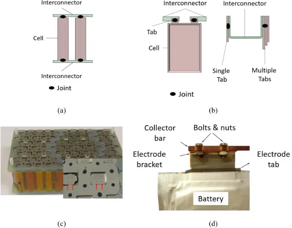
The most commonly deployed joining technologies are ultrasonic welding, wire bonding, force fitting/mechanical assembly, soldering and brazing, laser and resistance spot welding. Besides those, the work at hand also considers friction stir welding, tungsten inert gas welding, joining by forming and adhesive bonding. Those technologies will be presented in the following with focus on scientific literature assessing the suitability for battery joining tasks.
After this process the battery pack is placed in proper containers and it's cooling techniques are decided.
Mechanical Assembly:
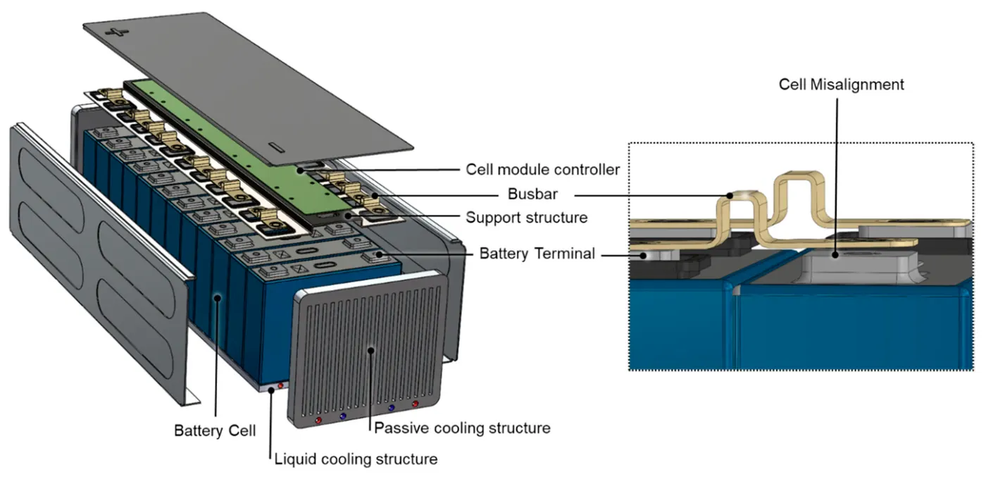
After this the testing is done to check for specifications and quality parameters. After this the Battery pack is shipped and stored.