Project 1 Mechanical design of battery pack
AIM:
Battery capacity: 18 KWh
Cell: ANR26650M1-B
Prepare a detailed battery pack drawing along with its enclosure. State your assumptions.
- Battery capacity: 18 KWh
Cell: ANR26650M1-B
Prepare a detailed battery pack drawing along with its enclosure. State your assumptions.
One of the basic components of an electric powertrain is the battery pack and is the major source of energy for vehicles and for high performance vehicles. It must supply energy to the vehicles at very high power. The battery of an electric vehicle must achieve the following:
- Provide maximum motor torque
- Vehicle range in terms of kilometer
- To achieve proper life cycle of the battery.
Thermal considerations must be kept in mind for the safety and performance of the battery pack as a result of increased heat generation in batteries at high charge and discharge rates which are necessary for high power output. Mechanical robustness is also a critical challenge, the battery pack should not only be able to withstand vibrations and loads from normal driving conditions and acceleration and decelerations, but also maintain structural integrity in crash scenarios. One important safety for lithium ion batteries is that when they are impacted they could be extremely dangerous and cause catastrophic failures for the entire battery pack.
In this project, we will be using the cell ANR26650M1-B for our battery pack so as to calculate the parameters which are required to build the electric vehicle battery pack. The parameters which will be considered are the electrical aspects such as the temperature, depth of discharge, energy density, battery capacity, and state of charge, state of health and ampere hour capacity. We will also be calculating the geometrical considerations like size, weight, volume and area. We would also be considering enclosure models for the battery pack.
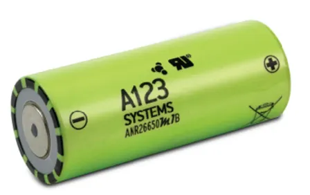
Lithium iron phosphate cell (LiFePO4)
Lithium ion cells are capable of delivering very high power. Lithium ion cells are used in various applications such as electric vehicles, mobile devices and other electronic devices. The battery pack is installed on the lower floor of the electric vehicle so that the weight is equally distributed and the center of gravity is maintained properly.
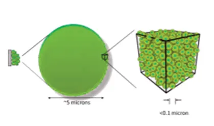
Lithium werks 26650 cells are capable of delivering very high power due to patented Nano phosphate battery technology. Based on the chemistry of lithium ion phosphate (LiFePO4) the cells are safe over wide range of temperature and conditions. Nano phosphate battery technology provides stable chemistry, fast charging consistent output, excellent life cycle and superior cost performance. It provides the base for safe system that meets the demanding customer requirement. Many layers of protections are employed at the chemistry, cell and system level so as to achieve a solution for energy storage with superior safety and abuse tolerance as compared to metal oxide lithium ion chemistries.
The advantages of Lithium iron phosphate cell (LiFePO4) [ANR26650M1-B] are:
- High power and energy density.
- Excellent safety performance and extensive life cycling.
- Light weight and compact.
- Low capacity loss and impedance growth over time.
- High usable energy over a wide range of SOC.
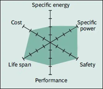
CHARACTERISTICS OF LITHIUM IRON PHOSPAHTE
Lithium iron phosphate uses lithium iron phosphate as cathode as it has good electrochemical performance with low resistance because of nano – scale phosphate cathode material. Lithium iron phosphate is often replaced by lead acid batteries as it has moderate specific energy, low tolerance and drastically reduced life cycle. These batteries are used in electric motorcycles and also in applications that require long lifecycle and significant safety. Cold temperatures reduce the performance of lithium ion and this could affect in cracking ability in extreme condition.
ADVANTAGES
- High specific power and provides a high level of safety
- It has a high lifespan and comes at a low cost
DISADVANTAGES
- High energy density causes the battery to be unstable. It heats up faster during charging which results in increase in temperature.
- The battery is unable to charge at temperatures below freezing.
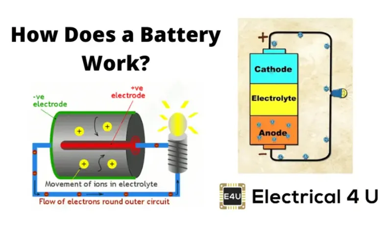
Battery is a device that stores chemical energy and converts into electrical energy. A battery is made up of one or more electrochemical cells with external connections for powering electrical devices such as flashlight, mobile phones and electric cars. When the battery is supplying electric power, the positive terminal is cathode and negative terminal is anode. The chemical reactions in a battery involve the flow of electrons from one electrode to another via an external circuit. The flow of electrons implies that there is flow of electric current that can be used to do work. To balance the flow of electrons charged ions also flow through the electrolyte solution which is in contact with both the electrodes. Depending upon the electrodes and electrolytes different chemical reactions are produced that affects how the battery works, how much energy it can store and its voltage. The difference in potential difference between the electrodes indicates the force with which the electrons will travel between the two electrodes. This is also known as electrochemical potential which determines the cells voltage. Greater the difference greater will be the electrochemical potential and higher the voltage will be.
BASIC TERMINOLOGIES OF BATTERY
- VOLTAGE, CUT OFF : Voltage at the end of useful discharge
- VOLTAGE , NOMINAL : Voltage of a fully charged cell when delivering rated current
- DEPTH OF DISCHARGE: The amount of energy which is removed from the battery. It is usually expressed in terms of percentage of the total capacity of the battery. For example: if 80% is depth of discharge means that 80% of the battery has been discharged and 20% charge is remaining in the battery.
- STATE OF CHARGE: It is expressed as percentage of energy when fully charged and measured under the same discharge conditions. If the battery is fully charged it indicates that is 100%.
- VOLT : Potential difference between the electrodes that causes the current of 1 ampere to flow through a resistance of 1 ohm
- DISCHARGE RATE: Rate at which electrical current is removed from the battery. It is usually measured in mill amperes.
CALCULATING MECHANICAL DESIGN PARAMETERS FOR BATTERY PACK OF 18KWH
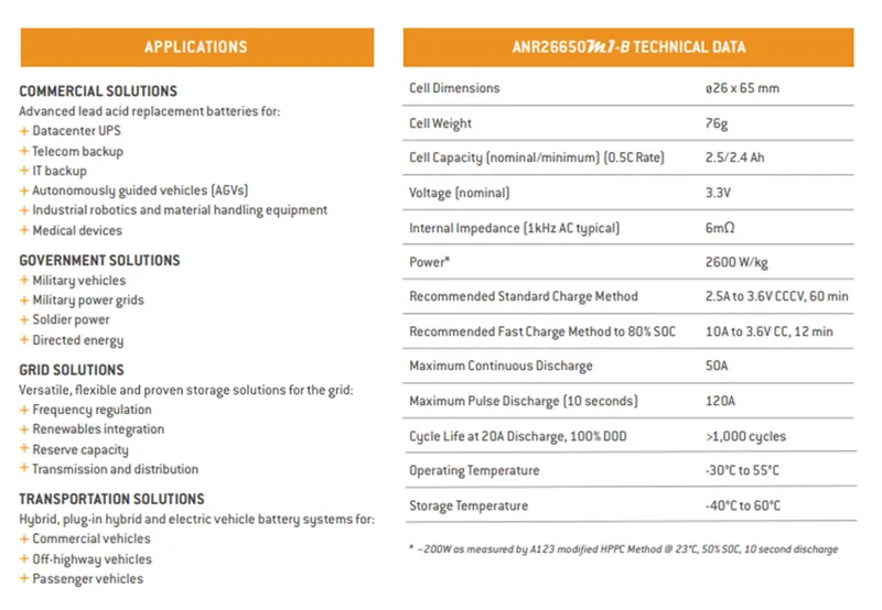
CELL SPECIFICATIONS: ANR26650M1-B
SPECIFICATIONS
NORMAL RATINGS:
Energy @ 25° C = 8.25 Wh
Specific power @ 25° C, 2 sec pulse > 4000 W/kg
Impedance (1 KHz AC) Typ = 6mΩ
Cycle life at 1C/1C, 100% DOD > 4000 cycles
DISCHARGING
Minimum voltage /HPPC Pulse = 2V / 1.6V
CHARGING
Recommended charge current = 3A
Maximum continuous charge current = 10A
Maximum pulse charge current = 20A
Float voltage = 3.45V
Recommended charge V and cut – off current = 3.6V, taper to 125mA
Temperature range (reduce charging current to 250mA when under 0°C) = 0°C to 55°C
MECHANICAL
Diameter = Ø 25.96 +/- 0.5mm
Length = 65.15 +/- 0.5mm
Mass = 76g +/- 1.0g
CERTIFICATIONS
Transportation = UN 3480 (UN 38.3) ,CIQ
Safety = UL 1642, IEC 62133-2
TRANSPORTATIONS
Shipping = Via Air @30%SOC
Via Sea @50%SOC
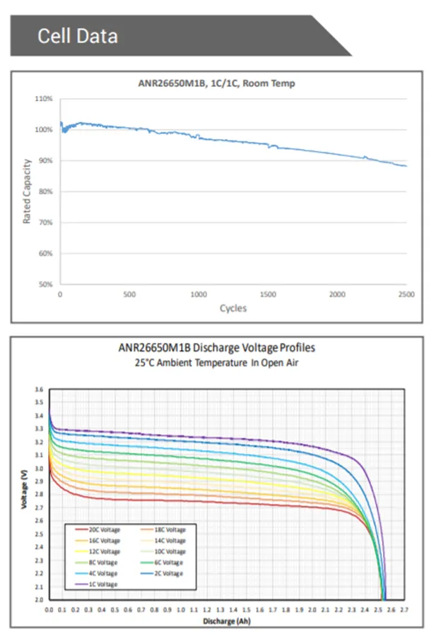
PLOT OF CELL BEHAVIOUR
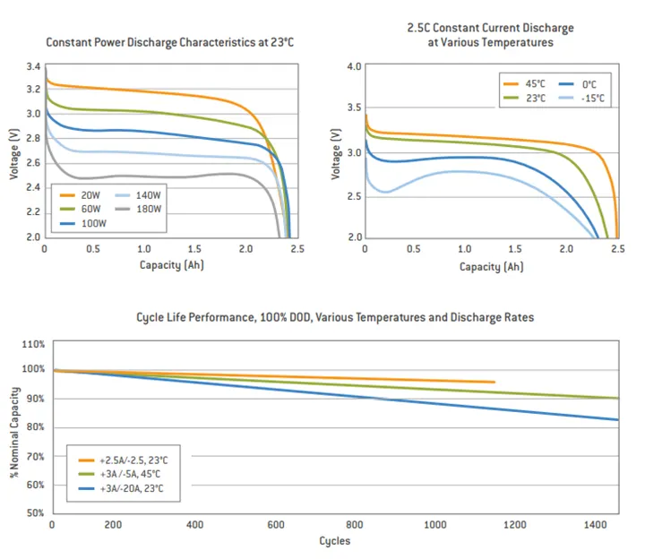
BATTERY CALCULATION:
Battery energy = 18Kwh
Voltage = 500V
Number of cells = energy / nominal voltage * capacity)
N = 18000 / (3.3 * 2.5)
N = 18000 / 8.25
N = 2182
We need minimum 2182 cells to get 18 Kwh energy, based on this we will decide how many cells should be in series and parallel.
In series configuration current remains the same and the voltage increases whereas in parallel configuration the voltage remains the same and the current increases.
We have assumed that 500V is needed to run the vehicle and nominal voltage of one cell is 3.3
So number of cells = voltage / nominal voltage
N = 500 / 3.3
N = 152
So 152 is the number of cells in series which is required to generate 500V
Now, to find out the number of cells in parallel
Cells in parallel = total no of cells / no of cells in series
= 2182 / 152
= 15
So the number of cells in parallel is 15
The cell architecture is 152S15P
Battery capacity
Capacity = number of cells in parallel * capacity of each cell
= 15 * 2.5
= 37.5 Ah
BATTERY DIMENSIONS
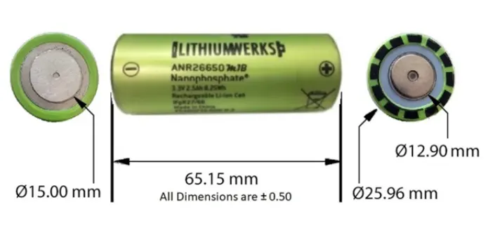
Length of the casing = 152 * 28 + 2 (cell diameter = 26 and assuming the gap between the cells is 2 mm)
= 4256 + 2
= 4258 mm
Breadth of casing = 15 * 28 + 2
= 420 + 2
= 422 mm
Height of the casing = 65 + 35 (height of the cell + margin for cell holder metal strips and wiring)
= 100 mm
Volume of the enclosure = l * b * h
= 4.258 * 0.422 * 0.100
= 0.1796 m 3
WEIGHT OF THE BATTERY PACK:
Cell weight = 76 g
Number of cells = 2182
Battery pack weight = cell weight * number of cells + weight of accessories (weight of the accessories include battery management system, battery holders, interconnects that provide electrical conductivity between them and cutoff switches)
= 76 * 2182 + 4.5
= 170.3 Kg
CELL CALCULATIONS
Cell volume = π r 2 h * no of cells
= 3.14 * 0.013 * 0.013 * 0.065 * 2182
= 0.0752m3
Cell energy = Nominal voltage * Nominal cell capacity
= 3.3 * 2.5
= 8.25 Wh
Cell energy density = cell energy / cell volume
= 8.25 / 0.0752
= 109.70Wh/m3
Specific energy density = Energy capacity of the battery pack / weight of the battery pack
= 18000 / 170.3
= 105.69 Wh/Kg
Battery pack is defined as a set of identical batteries which can be configured in series, parallel or a combination of both so as to achieve the desired voltage and capacity. The term battery pack is used in various applications like cordless tools, remote control cars and battery electric vehicles. Components of battery pack include individual batteries and interconnects provide electrical conductivity between them.
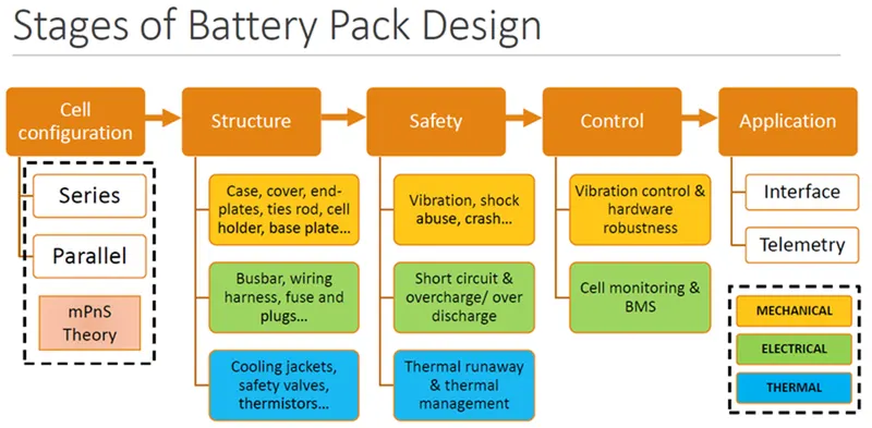
To make the battery pack durable and less prone to damages mechanical design of the battery pack should be taken care of. As shown in the block diagram below a typical battery pack design procedures in which the blocks in golden yellow are part of the mechanical design.
ADVANTAGES OF BATTERY PACK
- Easy to recycle and reduces wastage
- Flexibility of design and implementation is easier
Safety and reliability are the two main factors for large battery packs while designing the battery pack some technical criteria should be followed:
- Better cooling to prevent thermal runaway.
- Reduce Mechanical vibration.
- Serviceability and recyclability.
CELL CONFIGURATION
There are two types of cell configuration
- Series configuration
- Parallel configuration
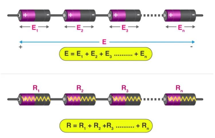
- SERIES CONFIGURATION
In series configuration the positive terminal of one cell is connected to the negative terminal of the next cell. Series connection involves connecting of two or more batteries together so as to increase the voltage of the battery pack keeping the current constant.
- PARALLEL CONFIGURATION
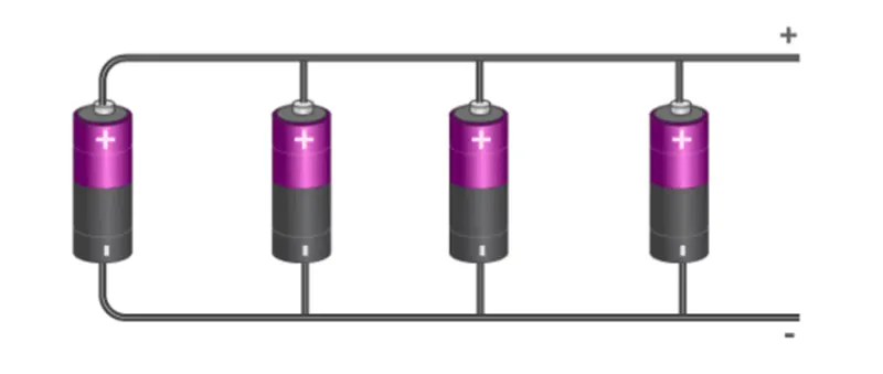
In parallel configuration the positive terminal of the cell are connected together and similarly the negative terminal of the cells are connected together. Parallel connection involves connecting of two or more batteries together so as to increase the current of the battery pack keeping the voltage the same.
COMPONENTS OF BATTERY PACK
- Cells
- Battery management system
- Connection system ( connector , wires)
- Housing ( sheet metal , shrink )
- CELLS
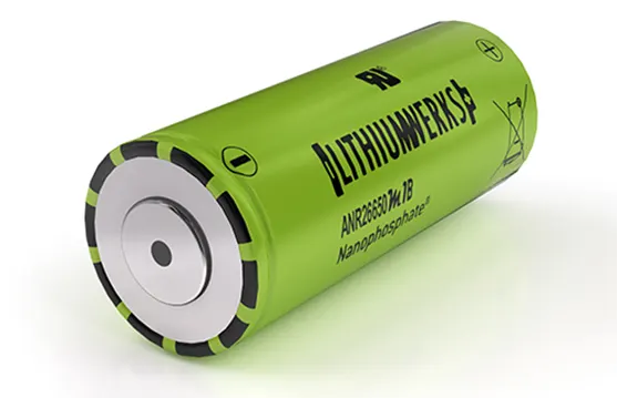
A cell refers to single anode and cathode separated by an electrolyte so as to produce the voltage and current. A battery is a source of electric power which consists of one or more electrochemical cells that stores chemical energy and converts into electrical energy. The individual cells can be configured in series or parallel connection so as to obtain the desired configuration of the battery.
- BATTERY MANAGEMENT SYSTEM
Battery management system is designed in such a way so as to monitor the parameters associated with battery pack and its individual cells, apply collected data to reduce the risk and increase the battery performance.
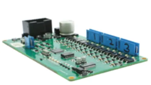
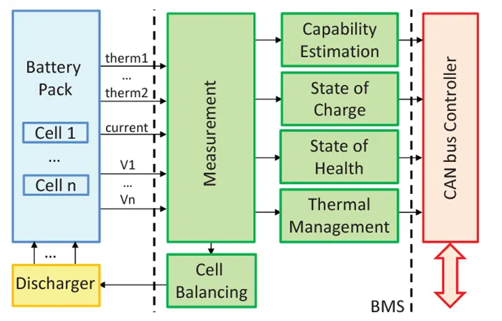
The above flow chart gives information of the battery management system working in synchronous with the battery pack. The inputs which are given to BMS from the battery pack are current, voltage and temperature. Based on the inputs which are fed to the battery pack the battery management system will give outputs such as SOC, SOH, Thermal management and capability of total battery pack. The outputs of the BMS are given to the CAN bus controller to communicate with the dashboard of the vehicle. Cell balancing is done to make sure that the maximum battery pack is fully utilized while charging and discharging.
- CONNECTION SYSTEM
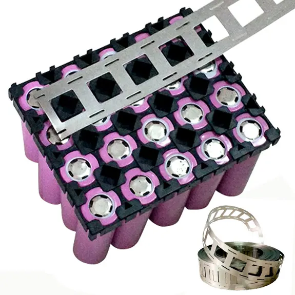
Connection system is what makes the cells connected together to form a battery pack using nickel strips. Nickel strips is used in battery building due to its efficiency in spot wielding and soldering and prevents corrosion over period of time. It is resistant to many corrosive environments. Nickel never gets rusted after it is applied to battery packs and won’t affect the transfer of current between batteries.
- HOUSING
These components are packaged so that the battery pack can be installed into a device. These components are placed and connected to one and another and are sealed with shrink wrap or hard case. They provide protection to the battery pack and make sure there is less damage occurred when impacted.

THERMAL MANAGEMENT
Thermal management system controls the temperature of the battery by cooling, heating, insulation and ventilation. A cooling function should be installed in battery to prevent thermal run away and keep the battery temperature in control. A good insulation should be used that can slow down the fall or rise in battery temperature especially when the vehicle is parked outdoors to protect it against extreme cold conditions or extreme hot conditions. The cells should be placed in such a way that the temperature can be controlled.
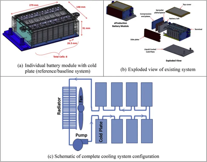
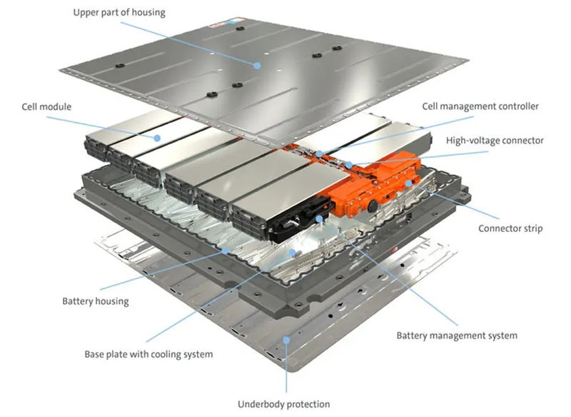
In the diagram below the modules are connected as required and the battery pack along with other necessary systems are enclosed.
STEPS IN DESIGNING THE CONSTRUCTION OF THE BATTERY PACK
- Choosing the right cells for the battery pack
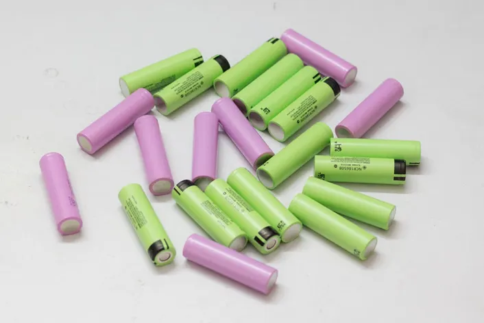
A wide variety of cells are available in the market. But it is important to stick to a particular cell with same chemistry and capacity so as to avoid any complications. We must make sure that all cells are balanced before making the battery pack, otherwise it would disrupt the performance of battery pack.
- Choose the right battery strips

The right battery strips should be used for connecting the cells together. Two types of strips are available in the market. One is pure nickel and the other is nickel plated over steel. Pure nickel is expensive but the resistance is low. Hence less heat generation leading to longer life of battery pack so preferred.
- Spot welding vs soldering
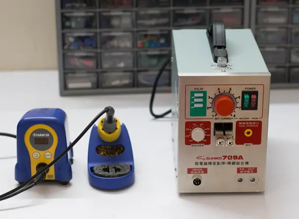
Spot welding securely joins the cells together without adding much heat to them. Spot welding is preferred over soldering because while soldering a lot of heat is applied to the cell which does not dissipate quickly. This will increase the chemical reaction in the cell and damage the performance of the cell and would result in reduction in capacity and life span of the cells.
- Checking the cell voltage
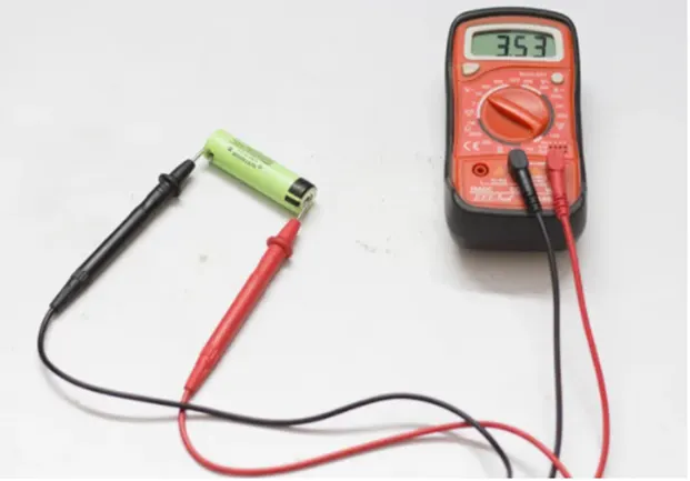
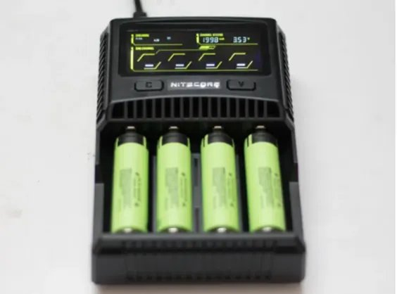
The individual voltage of each cell must be checked before connecting the cells in parallel. For parallel configuration the voltage of each cell must be the same if not high amount of current will flow from high voltage cell to lower voltage cell. This could damage the cells and could also result in fire on certain occasions.
- Battery capacity and voltage
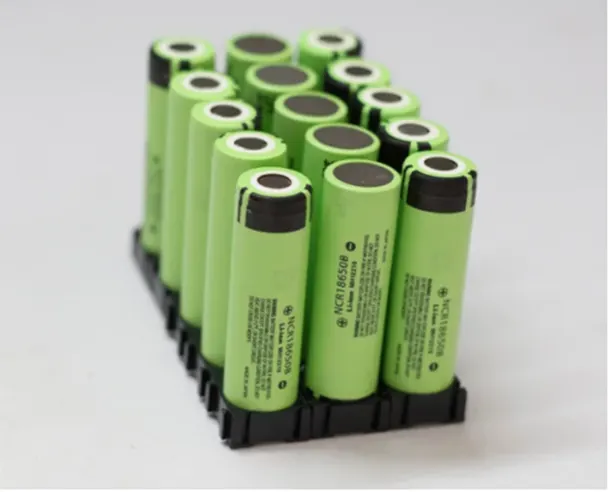
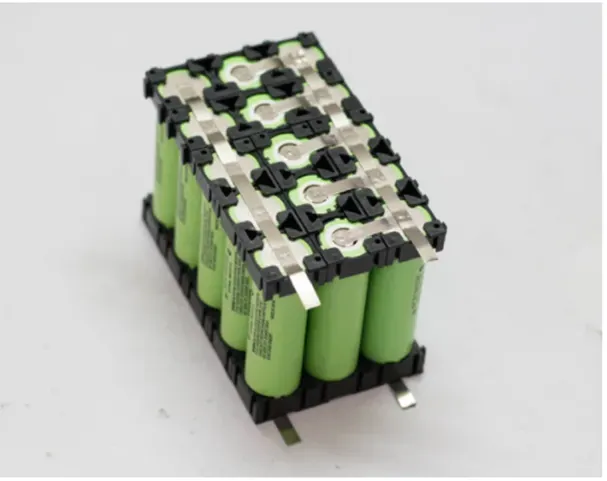
To construct the battery pack we must ensure the voltage and ampere hour of the battery pack. Cells must be connected in parallel so as to achieve the desired capacity (Ah) and such parallel groups are connected in series so as to achieve the desired voltage (V).
- Assemble the 18650 cells
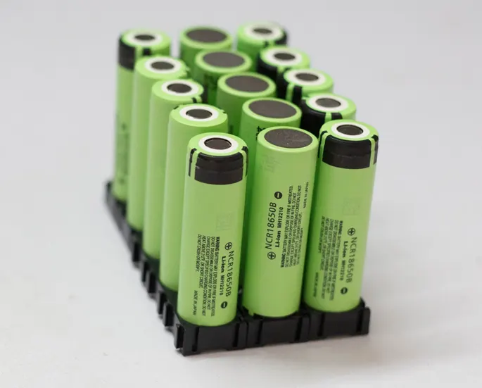
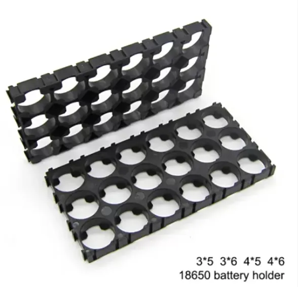
Firstly the parallel group of cells are placed with positive side up and then the second group of parallel cells with negative side up and lastly the parallel group of cells with positive side up.
The cells can be assembled together to make a pack by using a plastic 26650 battery holder. The advantages of using cell holders are:
- Holder provides support to the battery making it solid and reliable
- The holders provides space between the cells which makes the air to pass through it so as to easily cool the battery pack.
- Holders helps in preventing vibration of the battery pack.
- Spot welding the nickel strips
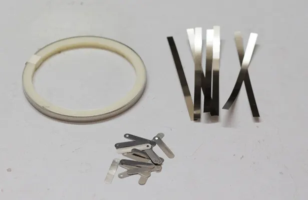
The nickel strips are cut and layed on top of the cells which are connected in parallel and should be ensured that it covers the cell terminals. Leave 10mm excess strips for connecting it to the BMS and then cut it. For series connection small nickel strips are cut as shown in the above figure. Connect the first parallel group of cells (negative terminal) to the positive terminal of the second group and then the negative terminal of the second group to the positive terminal of the third group. Make sure the quality of weld is good and it does not peel of easily.
- Adding the battery management system to the battery pack
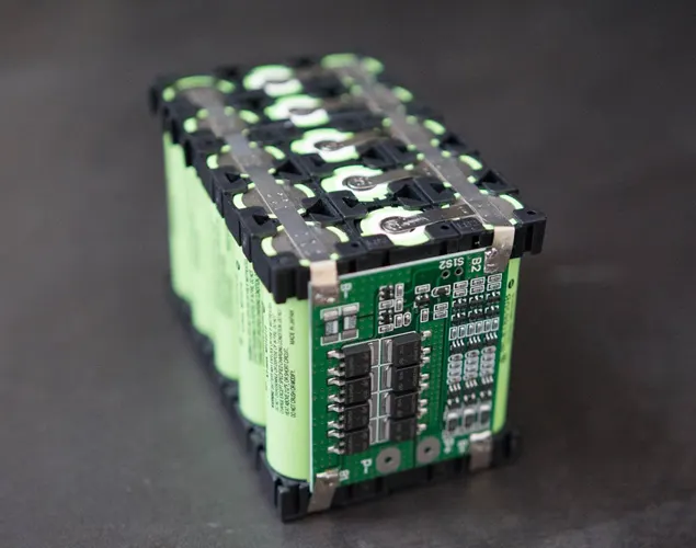
Finally the battery management system is added to the battery pack and its main functions are :
- Balances all the voltages of the cell equally
- BMS does not allow the battery pack to get over discharged.
- Monitors all the cells in the parallel group of the battery pack and disconnects it from the input source when it is fully charged.
The other alternative method to create a pack casing is to use shrink wrapping. Shrink wrap is a plastic film that can be wrapped around the battery pack irrespective of the shape and size. When heat is applied to the surface which causes the plastic to shrink. As the plastic shrinks it forms the shape of the pack and seals itself. It can even protect heavy battery packs.

ADVANATGES OF SHRINK WRAPPING
- PROTECTION: When heat is applied to the shrink wrap a tight seal is created which fully protects the battery pack. Once they are sealed it protects the battery pack from dust, dirt and moisture.
- DURABLITY: Shrink wrap is made from a durable plastic. It is difficult to tear and does not become fragile under extreme conditions. Once shrink wrap is heated and the object is sealed it does not become loose.
- AFFORDABILITY: In comparison to other packaging materials shrink wrap is very affordable it is designed in such a way that it reduces space and keeps the items close together without use of heavy materials like boxes.
For large arrangement of cells shrink wrapping is not an option. The battery pack is protected with metal or plastic housing. Usually Aluminum and high strength steel is used. An efficient battery housing has many features that help in passenger and battery safety, controlling the temperature of the battery pack and also protecting the battery from harsh environmental conditions and also form an accident. The battery box consists of four primary structural pieces top cover, bottom cover, internal structure and side impact protection structure.
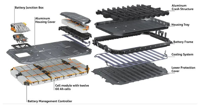
BATTERY HOUSING OF AUDI E-TRON
High strength steel is preferred over Aluminum.
- A high strength steel plate of minimum thickness of 1.2mm can protect the pack if there is any collision with a foreign object under the vehicle.
- Battery housing with multi chamber profiles made from high strength steel supports high load in the advent of side collision.
- There is reduction in manufacturing cost of 50% as compared to aluminum housing of the same dimensions.
- Through the help of high strength steel slim and thin walled crash structures are made which saves packaging space and also frees up room for large batteries.
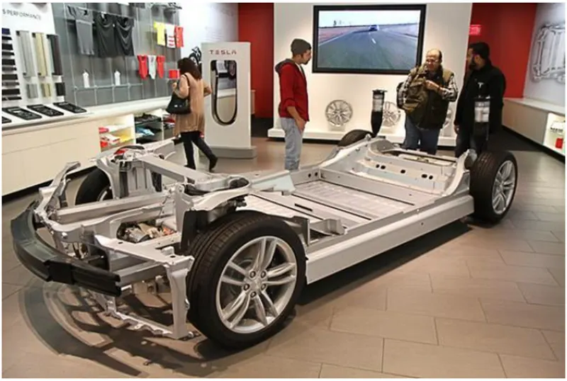
Placement of Battery Pack and Powertrain
CONSLUSIONS
The battery Pack designing should be carried out in an efficient manner and the utilization of it should be done in a precise way so as to increase the battery life and increase the range of the vehicle. Quick charging must be avoided as far as possible or it may reduce the life span of the battery.