Project 1 Mechanical design of battery pack
Cell: ANR26650M1-B
Intoduction:
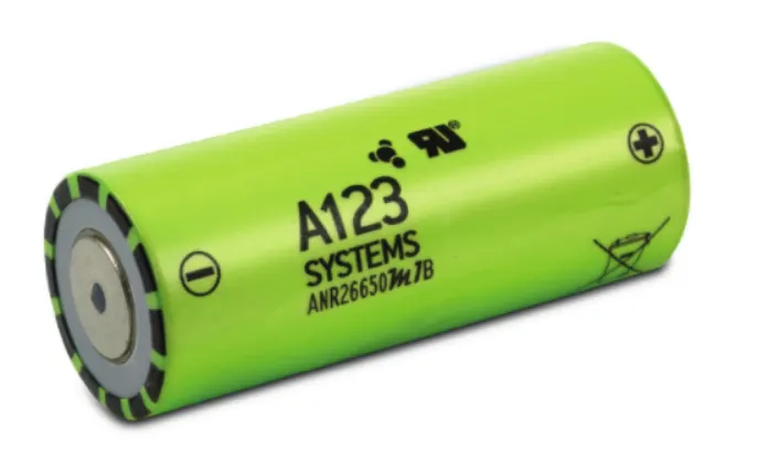
A123’s Nanophosphate lithium iron phosphate (LiFePO4) battery delivers high power and energy density along with excellent safety performance and extensive life cycling within a lighter weight and compact package. These cells have low capacity loss and impedance growth and also high usable energy over a wide state of charge (SOC) range and energy. This cell is suitable for a wide variety of applications in the toughest conditions, combining durability, reliability, and safety.
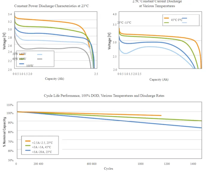
Cell Specifications:
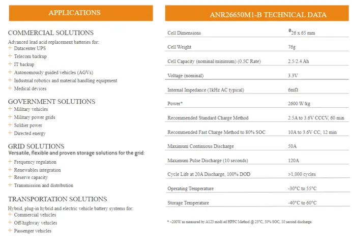
Appilications:
- Portable high power devices
- Battery backup systems
- Communication tachnologies
- Industrial equipment
- Electric vehicles (EVs)
Battery pack:
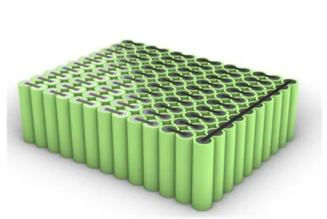
A battery pack is perferablly a set of batteries either configured in series, parallel or a mixture of both accordingly to deliver desired voltage, capacity or power density. These battery packs are more oftenly used in BEV's. In electric vehicles these battery packs are enclosed in casing for casing for ensuring safety.
Steps to Construct a Battery pack:
- Intially it is required to know the energy requirement.
- Then with that information, number of cells required to be calculated.
- Then configure the cells in series and parallel according to desired voltage and capacity.
- Calculate the pack dimensions and weight for preparing the casing pr cell holder to the pack.
- Then Battery pack assembly by placing them in cell holder according to the configuration.
- And then connecting the cells in series and parallel with the help of nickel strips by spot welding.
- Connect the BMS to the pack.
- Set a suitable thermal management technique to the battery pack.
- Placing in a enclosure for protection
Battery Pack Calculations:
- Energy:
given = 18000Wh
- Number of cells required:
Number of cells(N) = energy/(nominal voltage*capacity)
N=18000/(3.3*2.5) = 2182
So we need 2182 cells to get the required energy of 18KWh and these ceels should be configured in series and parallel for desired volatge and capacity.
- Series, parallel configuration:
Series configuration:
Let us assume 330V is required.
Then number of cells in series Ns = voltage required/nominal voltage of one cell
Ns=330/3.3 =100
Thus number of cells to be connected in series are 100 cells.
Parallel configuration:
The number of cells in parallel Np = total no. of cells(N) / no. of cells in sereis (Ns)
Np = 2182/100
Np = 21.82
= Approx 22 cells
So the configuration of the pack is 100S 22P.
As we know the number of cell in parallel we can know find the battery pack capacity.
Battery pack capacity = Np * cell capacity
= 22 * 2.5
= 55Ah
- Battery pack dimensions and Weight for casing:
Weight of pack:
Given weight of cell = 76g
Weight of battery pack = number of cells* weight of cell
= 2182*76 = 165.8Kg
Dimensions of casing:

From the cell specifications the height and diameter of the cell are 65mm and 26mm respectively. So from this specification the casing dimension must be calculated.
Let the margin or seperation of 2 cells be 4mm and the height of margin for wiring and cell holders be 35mm.
Here as series connected cell are more, so the length is decided by series connected cells and breadth is decided by parallel connected cells.
Length of casing = number of series cells * (cell diameter + margin of cells)
= 100 * (26+4)
= 3000mm
Breadth of casing = number of parallel cells * (cell dia + margin)
= 22 * (26+4)
= 660mm
Height of casing = height of the cell + height of margin
= 65 +35 =100mm
- Battery pack aasembly:
Cell holders:
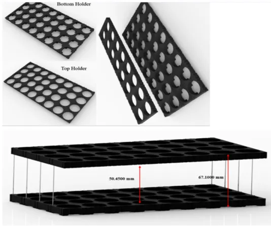
Here a cell holder is taken or prepared to place the cells according to the configuration i.e., here all the 2182 cells can be place in a single holder with 100*22 blocks or can be sub divided or configured into small matrices without change in desired specifications so that the size of holders can be reduced.
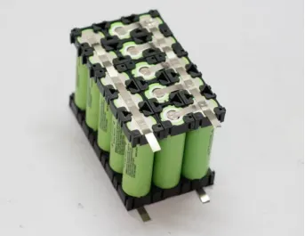
These cells are assembled in series and parallel in this way as shown
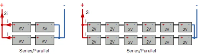
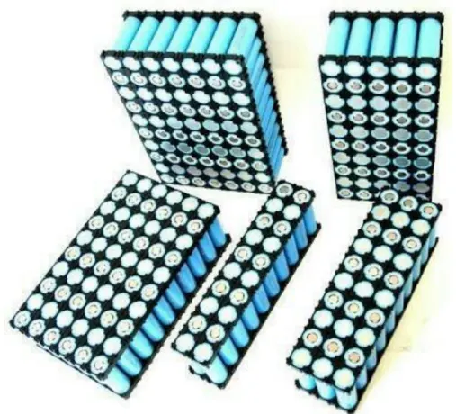
If in parallel all cell placed in same manner, and if in series cells are placed upside down in alternative blocks.
Soldering / Spot Welding:
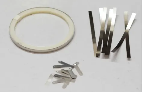
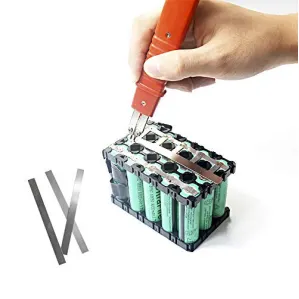
Most of the battery packs are spot welded using nickel strip for the contacts. Soldering directly to the cells is dangerous for the cells. This causes melting or disturb the safety vent or cause internal shorting if the heat is too high. Nut the reason for using soldering is not everyone will have a capacitive discharge spot welder.
Here in this nickel strips are used to connect the cells either in series or parallel by spot welding.
Wiring and Installation of BMS to pack:
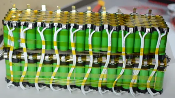
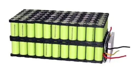
Connect wires to the battery pack at necessary places and then connect them to the BMS reuired pins. Then glue the BMS to any side of the battery pack.
Wiring
BMS installation
Installation of Thermal management:
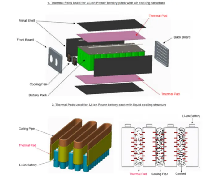
Here installation of thermal management tecnique like Air cooling or liquid cooling is placed to the battery pack as shown below.
Enclose and Heat shrink wrapping:
Then enclose the battery pack which is made of plastic or any metal like alluminium or the battery pack can either be wrapped by a plastic sheet.
Heat shrink tubing is a electrical insulation that activates and shrinks when heat applied. And the main reason for using this in the battery pack is to protect the batteries from metal to metal contact i.e., this wrapping ensures from no contact of postive and negative terminal of battery which result in short circuit battery.

Heat Shrink wrapping
Conclusion:
Thus the procedure of mechanical design of a battery pack is discussed and understood.