Project 1 - Loss calculation for a DC/DC converter-MATLAB
1.LOSSES CALCULATION
- Extending the learned lessons in previous module, you will be diving into another power electronics concept on your own.
- Design of boost converter, and calculating the loss of different components including power switching device and deriving efficiency of boost converter. This is applicable in power supply industry, electric vehicles etc where DC-DC converter is required to boost the voltage from DC source. All the aspects of this project with loss calculation, device selection, simulation etc are industry relevant.
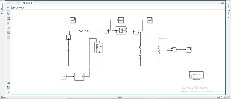
Simulation of boost converter:
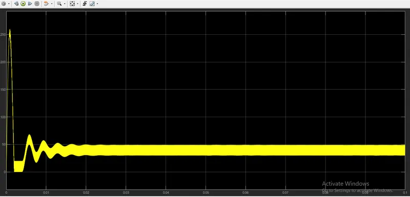
Current across inductance:
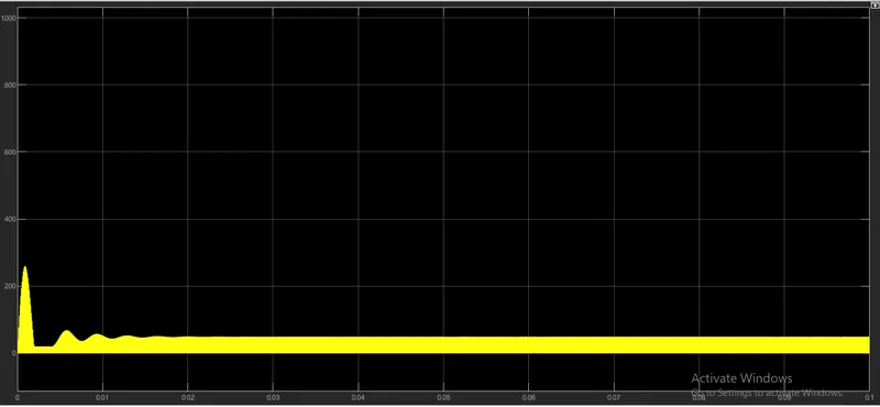
Current across diode:
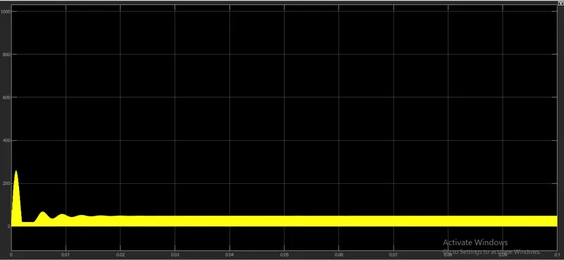
Current across capacitance:
Formula and calculation:
Losses in the MOSFET:
The transistor dissipates energy during the firing phase , the conduction phase , and the blocking phase corresponding to a Total energy : per switching period. For a MOSFET, the behavior in conduction regime is similar to that of a resistor, the powers dissipated during this phase and during the switching phases are defined according to the following equations:
Swirching loss = I^2*Rs*D
I = 50
Rs = 3.5 mOhms
D = 0.5
= 50^2*3.5*10^-3*0.5
Swirching loss = 4.37W
Losses in the diode:
When the diode is blocked, it behaves like a perfect capacitor because there is virtually no current flowing through it and only the voltage across it varies. When it is on, the voltage and the current vary. The other losses of the diode have been taken into account in the switching losses of the MOSFET, only the conduction losses are considered here. These are in the form of:
PF=(1−D) [Rd⋅I^2in+Iin⋅VF]
= (1-0.5)(0.001*50^2+50*1.2)
= 0.5*2.5+60
= 0.5+62.5
PF = 31.25W
Losses in the capacitor:
In most cases, a capacitor is a simple capacitance C expressed in Farad but as a component the capacitor is not limited to its simple capacity:
Pcap= Rc*I^2
= 2*10^-3*50^2
Pcap = 5W
Losses in the inductor:
The equivalent electrical model of a wound inductor can be reduced to an ideal inductor in series with a resistor . The presence of the latter generates direct losses by Joule effect linked to the conductors and to the losses induced in the magnetic core (losses by hysteresis and by eddy currents) which depend on the frequency and the variation of the flux.
Pind= RL*I^2
Pind=RL*I^2in+(RL/12)*(D∗Vin/f∗L)
= 0.01*50^2+(0.01/12)*(0.5*100/50*0.0002)
= 25+0.00083(5000)
= 25+4.15
Pind = 29.15W
Total power loss = switching loss + PF + Pcap + Pind
= 4.375 + 31.25 + 5 + 29.15
Total power loss = 69.7W
Power = Voltage(V) * Current(I)
= 100 * 50
Power = 5000W
Global study of the losses for a static converter:
As described in the previous section, the constituents of the Boost converter are: MOSFET, Diode, Inductance and Capacitance. The conversion efficiency can be written as:
ηConversion= Pout/Pin
=Pin−Plosses/Pin
= (5000 - 69.7)/5000
= 4930.3 / 5000
ηConversion = 0.986
= 0.986*100
ηConversion = 98.6%