Project 1 - Interfacing a 16*2 LCD with Arduino using I2C protocol
Overview of the Project:
In this project implementing the Code for “Interfacing a 16*2 LCD with two Arduino’s (one for Master and one for Slave) using Inter-Integrated Circuit (I2C) communication protocol” by sending the message to LCD using I2C communication protocol and display the message on LCD screen.
Goals:
- Communication between Arduino and 16*2 LCD using I2C protocol.
- Displaying the message sent by Master and received by slave i.e. LCD display.
Key Highlights of the Project:
- Using the inter-integrated circuit communication protocol, transferring the data i.e. the message we want to display is sent to the LCD.
- Two Arduino’s connected to the LCD display and the communication is executed using I2C protocol between Arduino and the LDC display.
Deliverables of this project:
- Communication between the Arduino’s and LCD using I2C.
- The message passed from master to slave and displayed on the 16*2 LCD.
Expected Outcomes:
- Students will get the Knowledge of I2C communication Protocol and the Arduino.
- The Hardware connection of all components used in this project.
- Displaying the message sent by master (Arduino) and received by the slave (16*2 LCD display).
I2C Communication
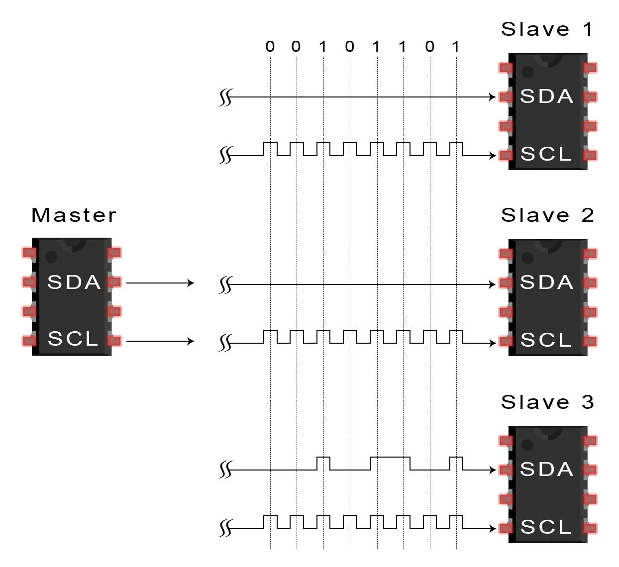
I2C is short for Inter-IC. And it is a type of BUS. This is designed by Philips semiconductors. I2C is a synchronous, multi slave, multi master packet switched, single-ended serial bus. ie. multiple chips can be connect to the same bus.I2C uses only two bidirectional open collector or open drain lines, Serial Data Line (SDA) and Serial Clock Line (SCL), pulled up with resistors. Typical voltages used are +5 V or +3.3 V, although systems with other voltages are permitted.
I2C Serial Interface Adapter
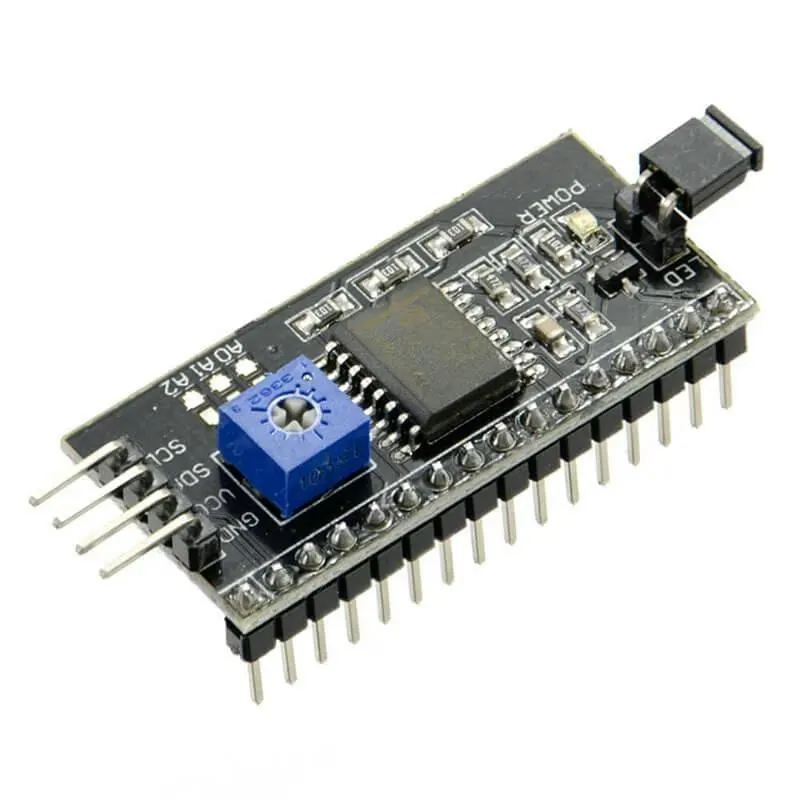
It is also known as I2C Module. It has total of 20 male pins. 16 pins are faced to rear side and 4 pins faced towards front side. The 16 pins for connect to 16x2 LCD and the 2 pins out of 4 pins are SDA and SCL. SDA is the serial data pin and SCL is the clock pin. The rest 2 pins for power supply (Vcc and ground).There is a POT on the I2C Module. We can control the contrast of the LCD display by rotating this POT. And there is a jumber fixed on the module. When we remove the jumber, the backlight of the LCD display will go OFF.
Address of I2C LCD
Before starting we need to know about addressing of I2C devices. Every device which can attached to MCU have an address. We need to know this address for communicate with that particular device.
You can see three solder pads on the I2C module. which is labeled as A0, A1 and A2. This is Address selectors. ie, each solder pads have one upper potion and a one lower potion. if, there is a connection between upper potion with lower connection it is called "Connected" otherwise it is called "Not connected". When A0, A1, A2 are in "Not Connected" condition ( A0 = 0, A1 = 0, A2 = 0) the address would be 0x27. In default the A0, A1, A2 are in "Not connected" condition. And some time default address is 0x3F. There is no need to change the address of the I2C module when we use only one LCD. But when we use more than one LCD, need to change the address. Because two or more different device can't communicate with the same address. For more address see the table given below.
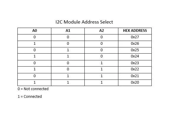
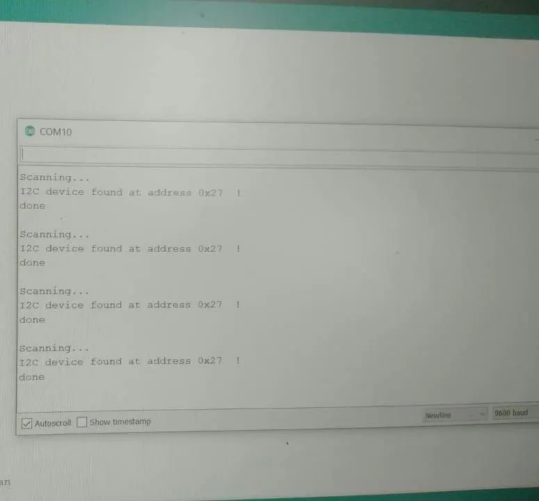
In some cases A0, A1, A2 are "Not connected" state, but the address is not 0x27. We can't communicate with this address. So we need to find the original address of that device. For that we need to run the Arduino with "I2C Scanner" code.
I2C Scanner Code
I2C Scanner code is used for find the number of I2C devices and address of I2C devices. First add the header file for include "Wire.h" library. Then in setup part, begin the "Wire" library by "Wire.begin()". Then begin the serial monitor as the baud rate of 9600 by "Serial.begin()". Next in loop part, define two variables with the datatype "byte" named "error" and "address". Then define another variable with the "Integer ( int)" datatype named as "Devices". And set initial value as 0. Next start a for loop with minimum value of 1 and maximum of 127. "address" used as loop variable. Next input the address to wire with the function "Wire.beginTransmission()". The i2c_scanner uses the return value of the "Write.endTransmisstion()" to see if a device did acknowledge to the address. This return value store the value to the variable "error". The return value become 0, if a device acknowledge to the address. Otherwise, the return value become 4. Next use a if. And the condition is "error==0". Then print the particular address to the serial monitor only if the address<16. Here we print the address in Hexadecimal. The printing instruction is "Serial.print(address, HEX)". And count the Device. The complete I2C Scanner code is given below.
#include <Wire.h>
void setup()
{
Wire.begin();
Serial.begin(9600);
Serial.println("\nI2C Scanner");
}
void loop()
{
byte error, address;
int Devices;
Serial.println("Scanning...");
Devices = 0;
for(address = 1; address < 127; address++ )
{

Wire.beginTransmission(address);
error = Wire.endTransmission();
if (error == 0)
{
Serial.print("I2C device found at address 0x");
if (address<16)
Serial.print("0");
Serial.print(address,HEX);
Serial.println("  !");
Devices++;
}
else if (error==4)
{
Serial.print("Unknown error at address 0x");
if (address<16)
Serial.print("0");
Serial.println(address,HEX);
}
}
if (Devices == 0)
Serial.println("No I2C devices found\n");
else
Serial.println("done\n");
delay(5000);
}
Connection
First solder the I2C Module. There is no label on the I2C Module for connecting to 16x2 LCD. So solder it with the help of the image given below
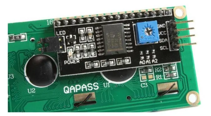
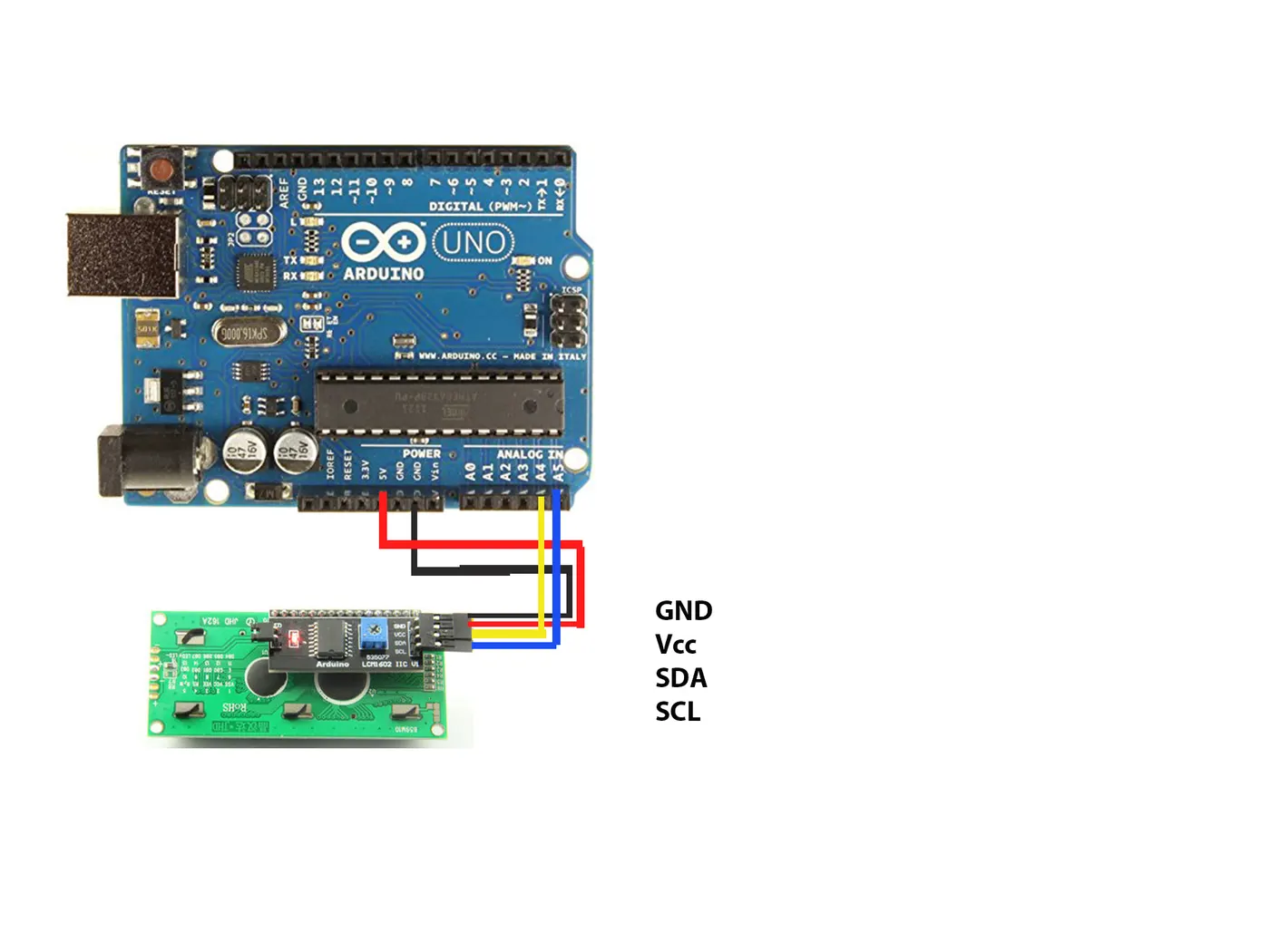
After soldering connect the I2C Module to Arduino Uno.
Arduino Uno I2C module
Analog Pin 4 - SDA
Analog pin 5 - SCL
5V - Vcc
GND - GND
Connect the Arduino to computer.
Next open Serial monitor from the icon on top right corner of Arduino IDE. And set the baud rate as 9600. Please ensure the correct port. Then you can see the address of LCD in serial monitor like shown below
Next I am going to display a text on our I2C LCD.
Before that need to add a library to Arduino IDE. Go to the link and download the library Arduino-LiquidCrystal-I2C-library. Then open Arduino IDE and go to Sketch>Include Library> Add.ZIP Library. Next select the downloaded ZIP file and click open.
Next create a sketch. First I include the header "Wire.h". This library help to communicate with I2C device. Then include "LiquidCrystal_I2C.h" for better communication with display.
Next set the address, number of column and number of rows using the function "LiquidCrystal_I2C lcd(). The address is 0x27 (discovered using the I2C Scanner Code). Number of columns is 16 and number of rows is 2. After this, we can call the display using "lcd". You can also use multiple I2C LCDs with Arduino Uno. But set different addresses and variable for each display.
Next code the setup part. First initialize the display using the function "lcd.begin()". If you have another display initialize them.
Next turn on the backlight using the function "lcd.backlight()".
Next clear the lcd using the instruction "lcd.clear()". Then set the cursor to the position (4, 0).
Now the LCD is ready to print. The cursor is at 4th column(count from 0), and 0th row(count from 0). Then print the Message "Hackster" by the function "lcd.print()".
Then leave the loop part as empty.
The programming is completed. Upload the sketch to Arduino and see the message on LCD.
//sketch created by Akshay Joseph
#include <Wire.h>
#include <LiquidCrystal_I2C.h>

LiquidCrystal_I2C lcd(0x27, 16, 2);

void setup()
{

	lcd.begin();


	lcd.backlight();
	lcd.clear();
	lcd.setCursor(4,0);
	lcd.print("Hackster");
}

void loop()
{
}
SCHEMATICS