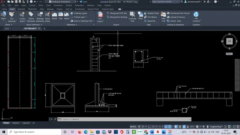
Project 1 _Creating an Architectural plan for the provided plot size and develop relevant basic structural drawings
Aim: - To create an Architectural plan for the provided plot size of 20’ x 60’ and develop relevant basic structural drawings.
Procedure: -
Given data: -
- Plot size is 20’x60’.
- Orientation is east facing.
Floor plan: -
- Units- Engineering.
- Limits- 200’x 200’
- Zoom; enter a; enter.
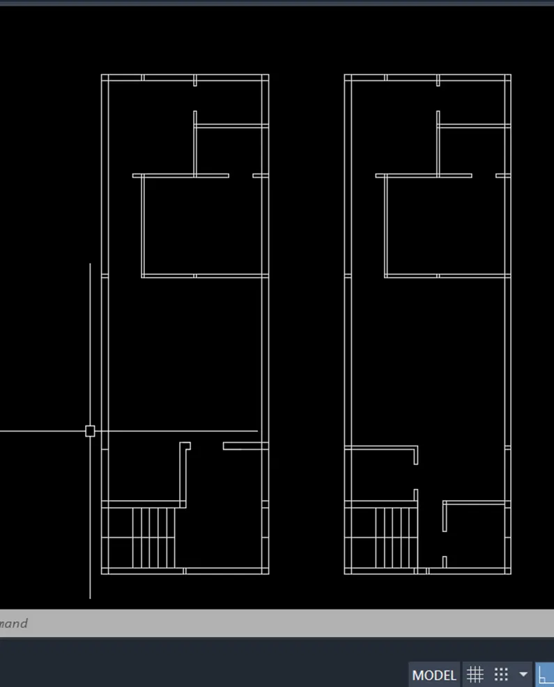
- Use xline command and draw horizontal and vertical line.
- Give offsets of 9” for external walls and room dimensions.
- Use line command to draw stairs.
- Trim the excess lines.
- Make a copy of the plan for first floor drawing.
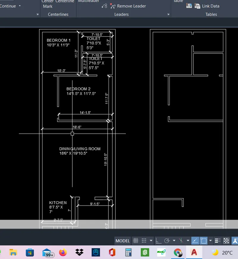
- Use dimlinear command to give dimensions.
- And Dtext command to give annotations.
- Make doors and windows using line and circle command.
- Copy paste doors and windows wherever required.
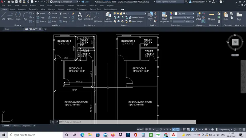
- Floor plan is created.
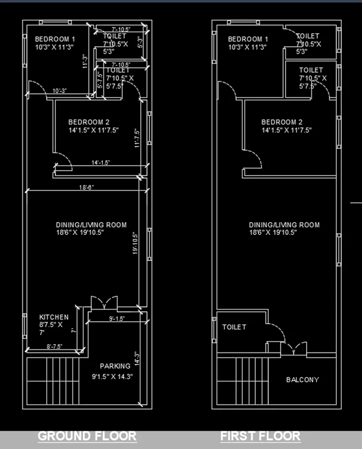
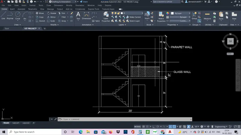
Front elevation: -
- Use xline command for projection of the front elevation.
- Draw vertical lines to show column, door, windows placements.
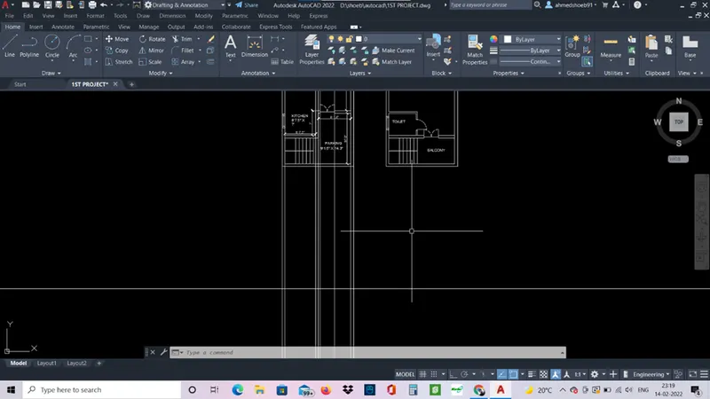
- Draw a horizontal xline and trim the excess lines.
- Horizontal line would be ground level.
- Give offsets of floor hieghts, slab thickness and parapet wall.
- Use line command and draw stairs for till one landing, mirror it for the next landing. Copy paste till for the next floor.
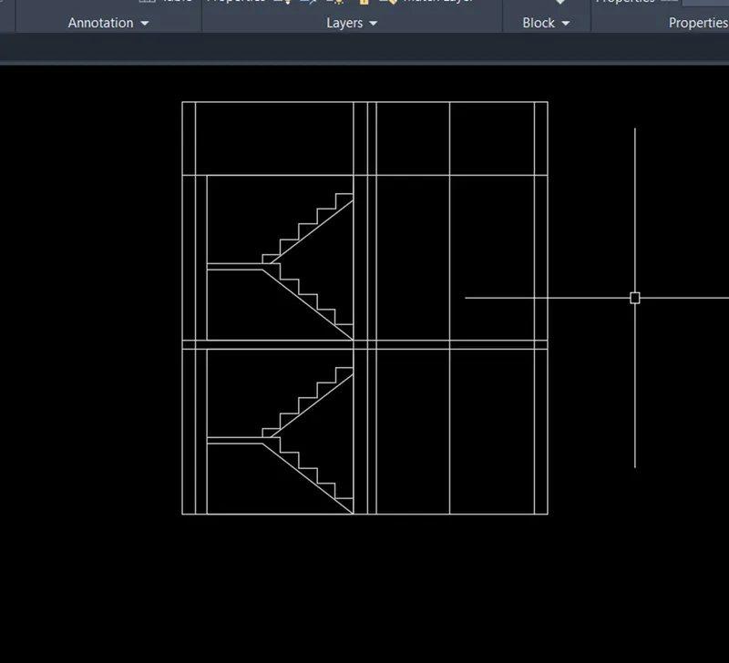
- Trim the excess lines.
- Use line command to draw doors, circle command for handle.
- Draw a 4’ glass wall for the balcony on first floor.
- Qleader command is used to give annotation.
- Dimlinear and dimcontinue command is used to give dimensions.
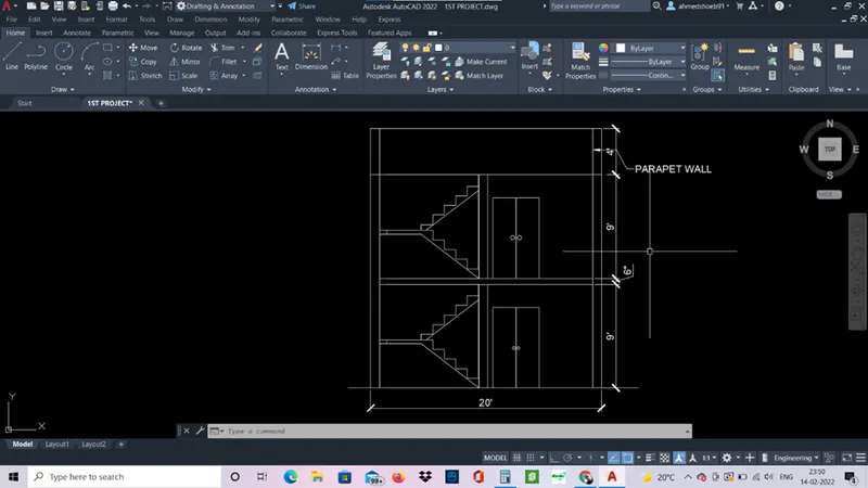
- Hatch command can be used to show the glass shade.
- Front elevation is created.
Side elevation: -
- Rotate the floor plan drawing @0.
- Same xline command is used for projections.
- Give offsets same as front elevation.
- Trim the excess lines.
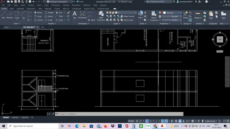
- Use line command to draw stairs.
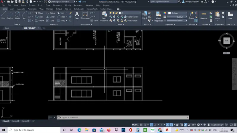
- Windows and vents are drawn accordingly.
- Dimensions and annotations are given.
- Side elevation is created.
Layout plan: -
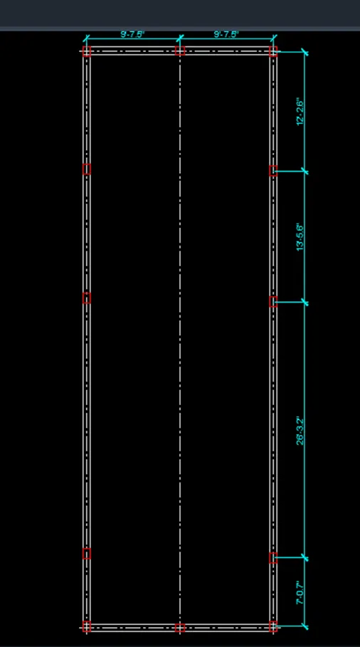
- Xline, offsets and trim command is used to draw 20’ x 60’ layout.
- Use rectangle command to 9”x12” columns.
- Use centreline command and set centrelines.
- Copy paste columns in required position.
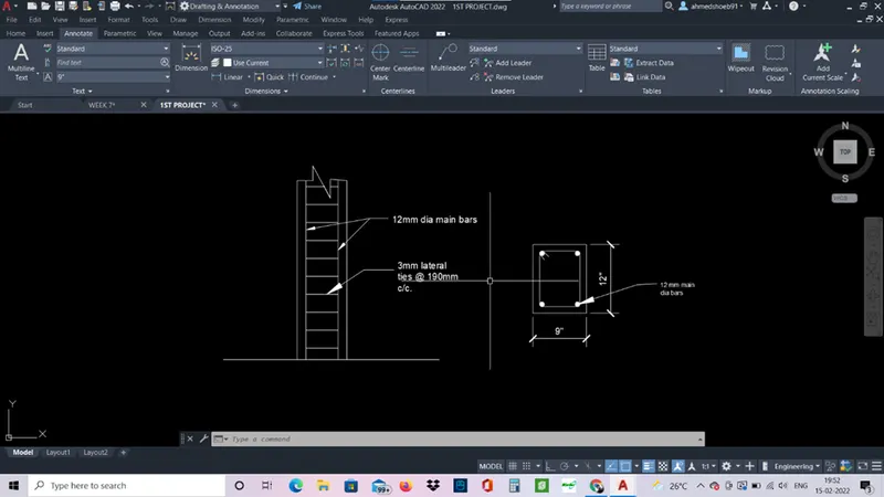
Column plan: -
- Columns 9”x12”
- Circle and donut command is used to show rebars from top.
- Qleader is used to show the main bars.
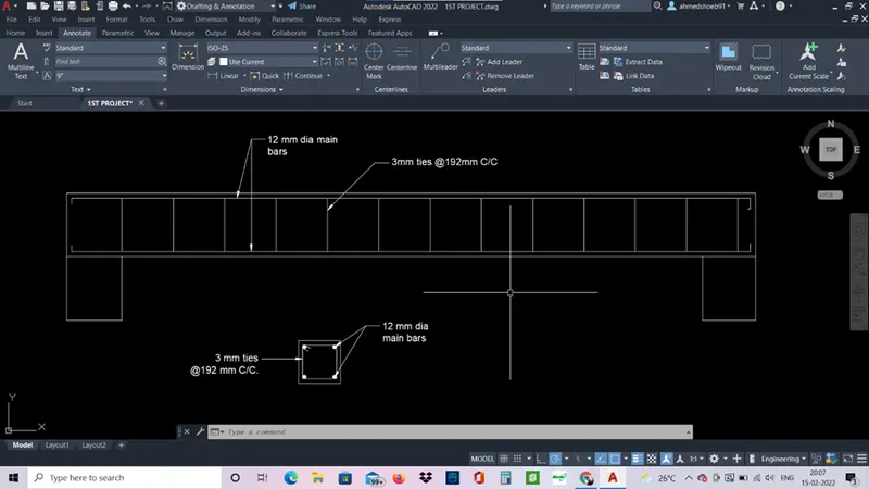
Beam plan: -
- Beam 9”x9”
- Drawn same as columns plan.
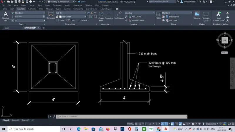
Footing plan: -
- Sloped footing is used.
- Footing bed is 4’x4’.
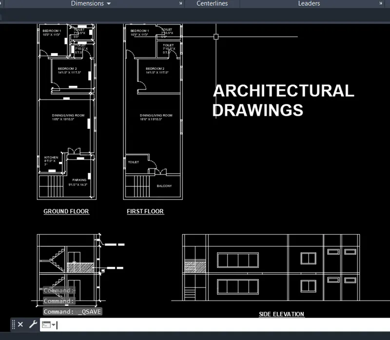
Result: -
Architectural drawings are done.
Structural drawing.
Drawing lines are scaled for viewing purposes.