Project 1 _Creating an Architectural plan for the provided plot size and develop relevant basic structural drawings
AIM- To Design and Draft a layout of a residential building
INTRODUCTION-
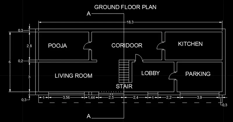
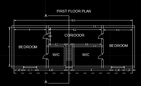
- floor plan- or house plan is a simple two-dimensional (2D) line drawing showing a structure's walls and rooms as though seen from above
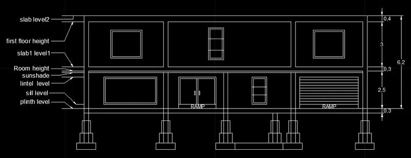
- elevation- refers to an orthographic projection of the exterior (or sometimes the interior) faces of a building that is a two-dimensional drawing of the building’s
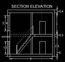
- sectional elevation- of a building is a elevation when seen through a vertical plane cutting through the part of the building
- beam- is a horizontal structural element that withstand vertical loads, shear forces and bending moments. The loads applied to the beam result in reaction forces at the support points of the beam.
- Column- is a vertical structural member that carry loads mainly in compression
- Footings- are structural elements that transmit load of entire superstructure to the underlying soil below the structure
GIVEN- a. Plot Size: 60’x20’(18.3m x6m)
b. Orientation- Facing East
PROCEDURE-
- Using command window open UNITS and select decimal and meter
- using rectangle tool create the plot of dimension 18.3mx6m
- select line command and draw the plan for (ground floor and first floor) and also draw the elevation as per the desired dimenion within the limits(18.3mx6m)
- cut the section and draw the section elevation using line tool
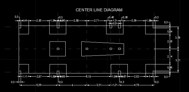
- draw the center line diagram for representing the footings locations
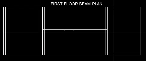
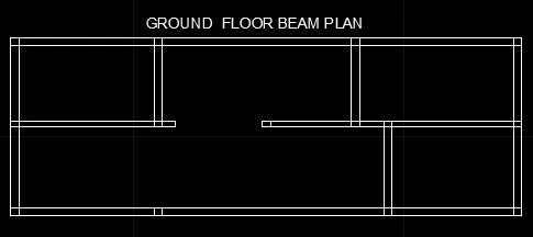
- using line tool draw the beams plan for ground floor and first floor
- select the dimension tool and give the dimensions to the drawing
- select multileader for representing diffrent levels in elevation
- select single line text and give the nomenclature where it is needed
RESULT