Creation of Multiple viewports, Scaling the drawing and setting in Template in AutoCad
Creation of Multiple viewports, Scaling the drawing and setting in Template in AutoCad
1.Aim : To Create a layout of the Plan and Section A of the project in Challenges 7, using the template TutorialmArch.dwt in a scale as given in the Figure
Introduction:
The layout templates are identified with a .dwg or .dwt extension.A layout template or layout from any drawing can be imported into the current drawing.
COMMANDS USED:
- Units
- Limits
- Xref
- Layout
- ATTEDIT
- Multiple viewports
- Model Space
- Paper Space
Procedure
Step 1 :
- Create a new AutoCAD file with imperial settings.
- Command D - units type as "Decimal" (dimension - mm) and set the precision also
- Set the limits with command "LIMITS" and enter zoom all.
- Command - UNITS to change the unit option as "Decimal" and set the precision.
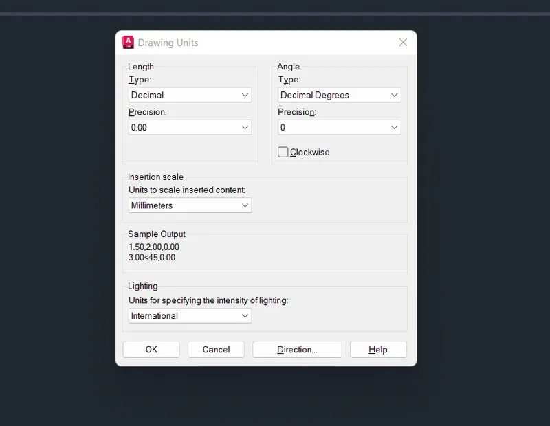
Step 2 :
- Command - XREF
- Select the attach the DWG file and choose the challenge 7 that was created
- Select the DWG file and Set the Reference type as "Attachment"
- Specify the scale as "Specify on the screen" and Insertion point as "SPecify on the screen"
- Select ok
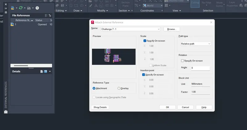
Step 3 :
- From the Xref option, select the drawing
- Right click and selct the bind option and press ok
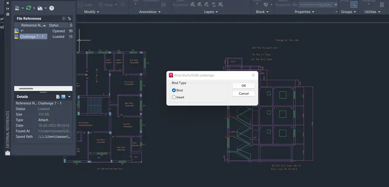
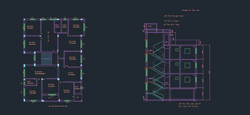
Step 4 :
- Command - Layout, to open the new Layout
- Type New in the command box and rename it as Plan & Section
- Right-click the plan and section from the layout tab
- Select the option called from the template option
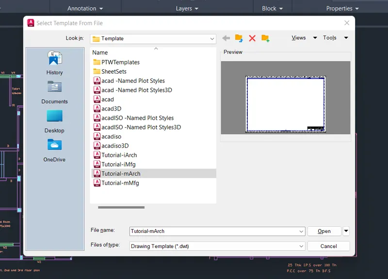
Step 5 :
- After inserting the Layout in the drawing,change the attributes
- Command - ATTEDIT and Edit Attributes dialog box appears
- Rename the title blocks
- After completing changes select ok
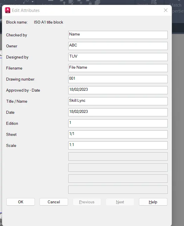
Step 6 :
- Command - MV
- Select the Viewports as Two: Vertical as shown in the figure below
- Adjust the Viewports according to the requirement.
- Command - MS to switch the mode into Model Space
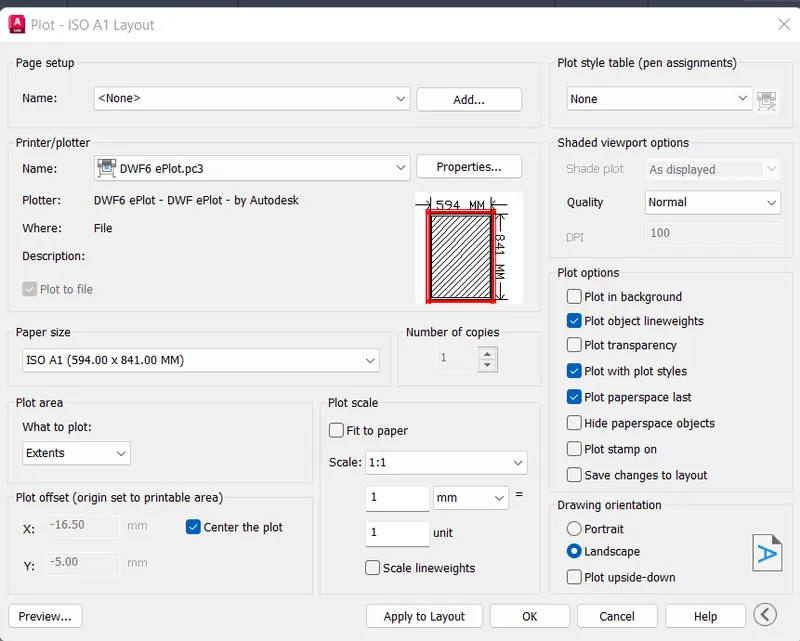
- Command - Plot to open the Plot and a print dialog box
- Select the Plot type as DWFx plot.pc3 and paper size as ISO A1
- Select the Plot area as Extents and Scale as 1:1 as per the given requirement
- Selct the preview button to preview the layout
- Click Ok to save the drawing.
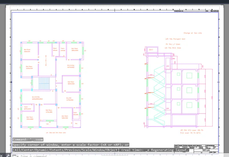
Result : The Layout of the Plan and Section-A has been Plotted Successfully using the Viewports.
***************
2. Aim : To Create a layout of the Kitchen drawn in Challenge 9 as shown in Figure
Commands Used:
- Viewports
- Multiple views
- Model Space
- Paper Space
- Pan
- Rectangle
- ATTEDIT
Procedure :
Step 1:
- Open the Autocad Application
- On the Autocad homepage, Click on Open drawing
- Open the Kitchen layout drawing that has been created in the challenge 10
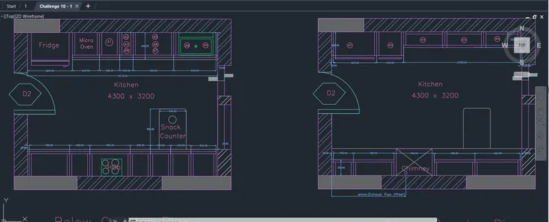
Step 2 :
- Now create the various views of the kitchen layout from the view tab
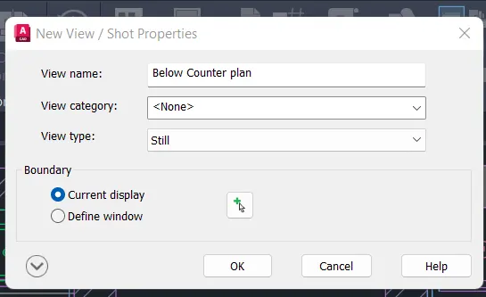
- Go to view tab and select the option - New View
- After selecting it a New view dialog box will appear
- Create the view name and Boundary as the "Current display"
- After making changes, click ok
- Similarly Create the other views of the kitchen layout using the view tab
Step 3 :
- Command - Layout to open the new Layout
- Type New in the command box and rename it as Kitchen plan
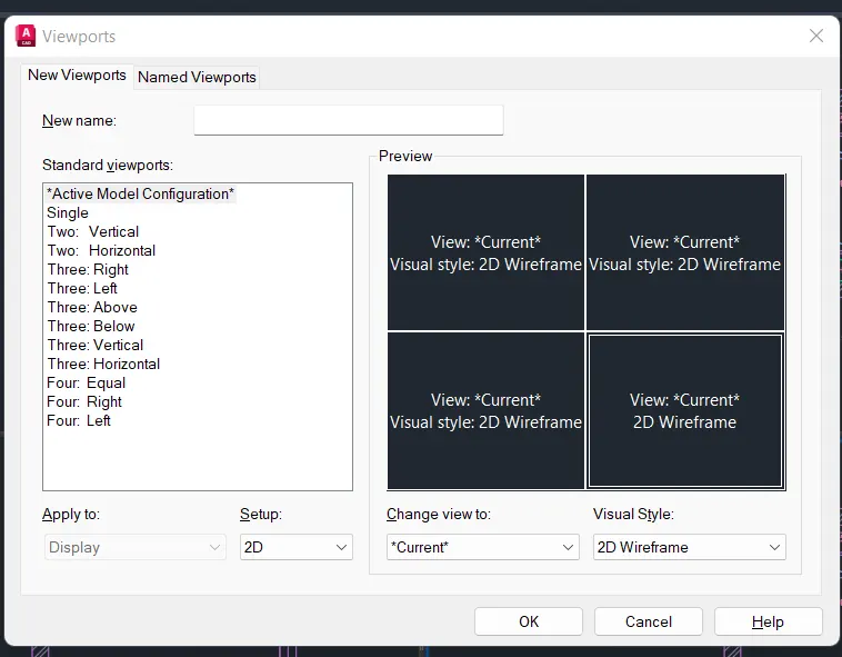
- Command - Viewport
- Select the Viewports as Four: Equal
- Adjust the Viewports spacing according to the requirement.
Step 4 :
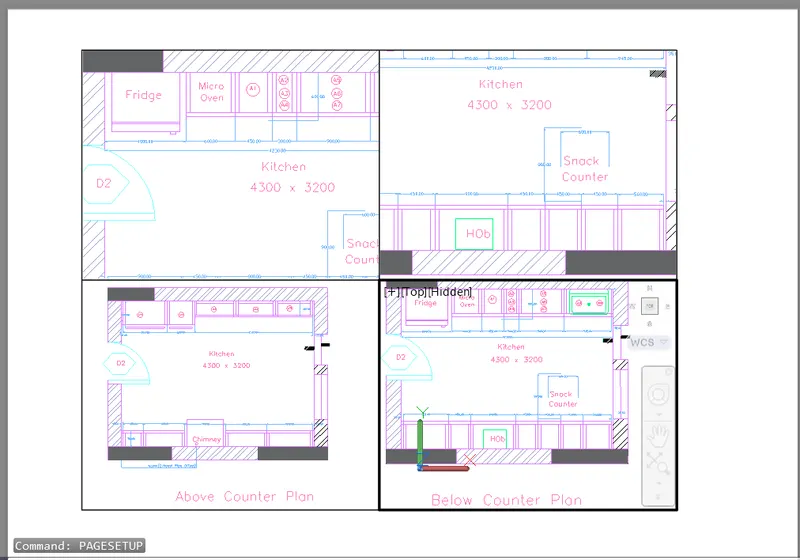
- After Creating the multiple viewports, adjust the drawing
- Command - MS to switch the mode into Model Space
Step 5 :
- Command - Plot to open the Plot dialog box
- Select the Plot type as DWG to PDF.pc3 and paper size as ISO full bleed A4
- Select the Plot and Scale as per the given requirement
- Click Preview and ok
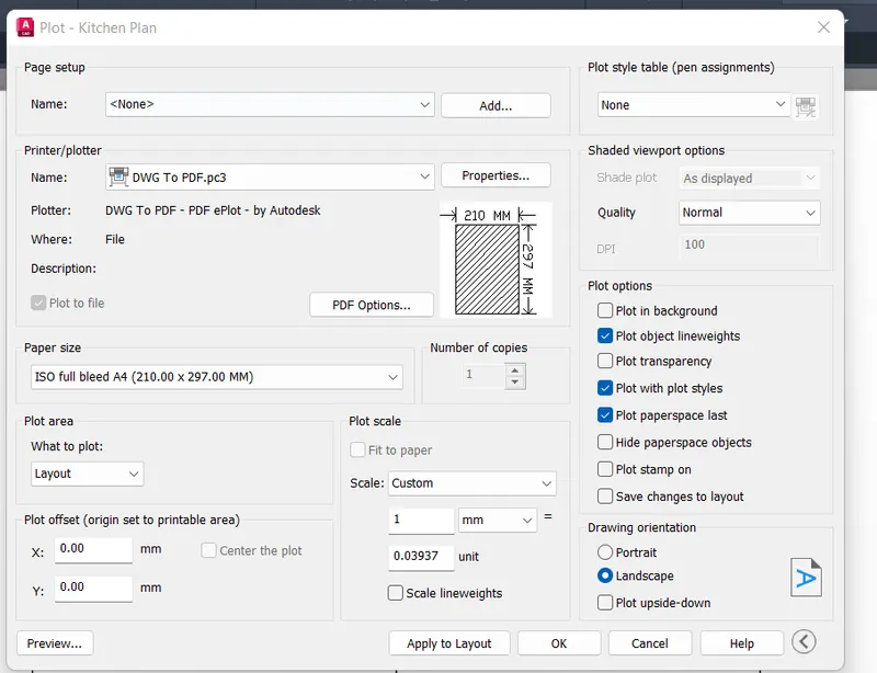
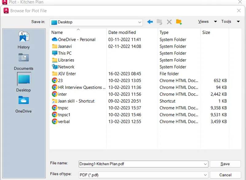
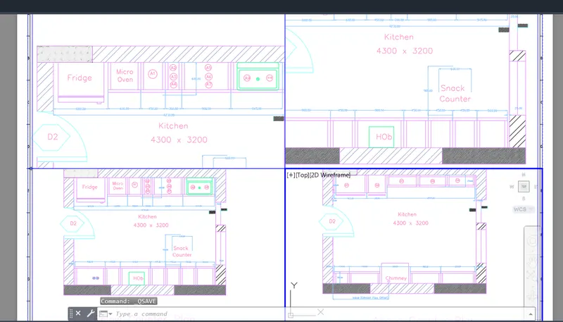
Result : The different views of the kitchen layout have been plotted using appropriate scaling in an A4 Sheet.
***************
3. Aim : Create a layout of the section created in Challenges 9.
Commands Used:
- Viewports
- Multiple views
- Model Space
- Paper Space
- Pan
- ATTEDIT
- Pagesetup
- Plot
Procedure :
Step 1:
- Open the Autocad Application
- On the Autocad homepage, Click on Open drawing
- Open the Kitchen layout drawing that has been created in the challenge 10
Step 2 :
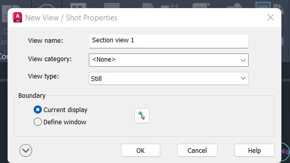
- Now create the various views of the Industrial layout from the view tab
- Go to view tab and select the option - New View
- After selecting it a New view dialog box will appear
- Create the view name and Boundary as the "Current display"
- After making changes, click ok
- Similarly Create the other views of the kitchen layout using the view tab
Step 3 :
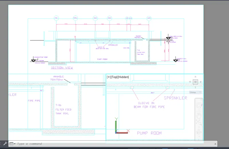
- Command - Layout to open the new Layout
- Type New in the command box and rename it as Industrial plan
- Command - Viewport
- Select the Viewports as Three: Above
- Adjust the Viewports spacing according to the requirement.
Step 4 :
- After Creating the multiple viewports, adjust the drawing
- Command - MS to switch the mode into Model Space
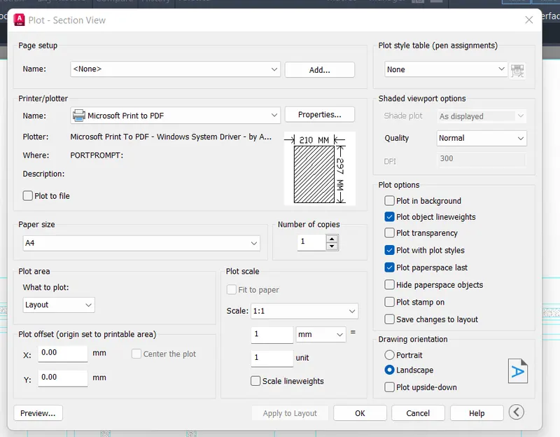
- Command - Plot to open the Plot dialog box
- Select the Plot type as Print to PDF and paper size as A4
- Select the Plot and Scale as per the given requirement
- Click Preview and ok
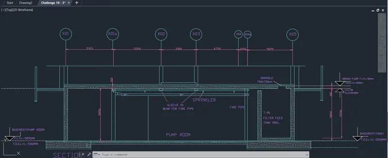
Result : The Different views of the Sectional industrial building have been plotted successfully using multiple viewport.