Project 1 _Creating an Architectural plan for the provided plot size and develop relevant basic structural drawings
Aim: To design and draft a layout of a residential building with following details
a. Plot size: 60'*20'(18.3m*6m)
b. Orientation: East facing
c. Develop
i. Architectural drawing (Floor plan, Elevations and Sections)
ii. Structural drawing (Column, Beam, Footing plan)
Introduction: Residential building will be drafted using AutoCAD drafting tools with given plot size of East facing.
- Plan is drafted within the area
- Assume all the dimensions
- East and North side elevation is drawn with help of plan projections
- Section AA & Section BB is also drafted with projections
- Column, Beam, Footing plan are to be drafted
Commands Used:
- Units
- Limmax
- Zoom
- Xline
- Line
- Command
- Offset
- Trim
- Dimensions
- Single line text
- Arc
- Ellipse
- Fillet
- Hatch
- Centreline
- Layer properties
Procedure:
- Open AutoCAD software
- Start new drawing
- Type UN in the command line and click enter
- Select Engineering or Architectural as drawing units
- Type LIMMAX in the command line and click enter
- Set the max limits as 100',100'
- Type Z in the command line and click enter
- Select All and click enter
- Type REC in command line and click enter
- The dimensions of rectangle are 60'*20'
- Make offset distance at 9"
- Draw interior walls with offset distance of 4.5"
- Draw doors using line and arc
- Draw windows, ventilators using line tool
- Staircase is drafted by using lines
- Plot the dimensions using Dimlinear command
- Use text command to type and place it
- Create layers for all by using layer properties and choose colours for it
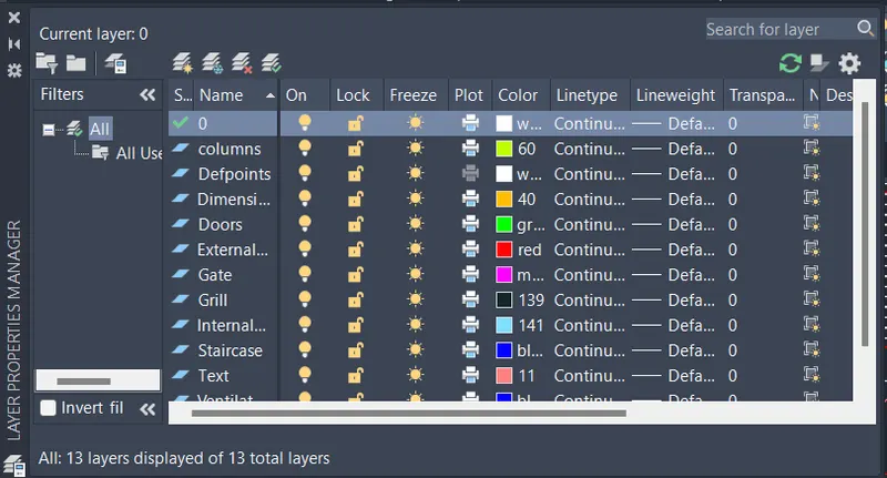
- The final image of drafted floor plan is as follows
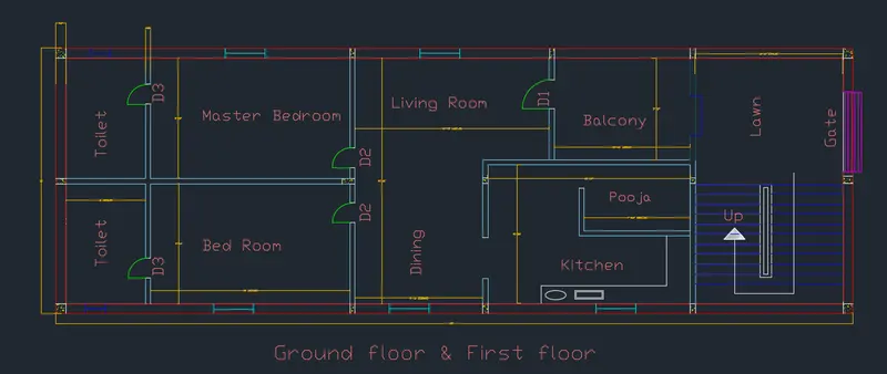
- Draw the elevation diagrams from the plan
- Draw the projections from plan on east direction
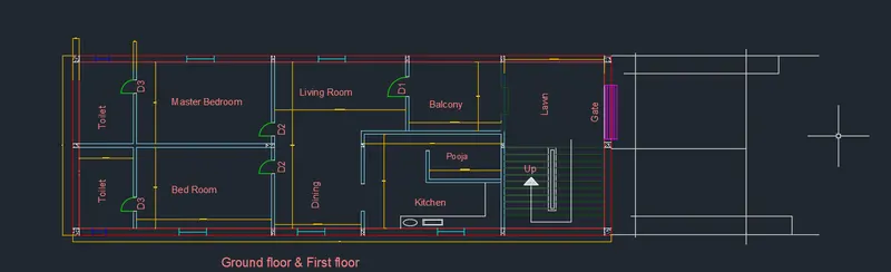
- Using trim, line commands draft the diagram
- Hatch it and the final image is as follows
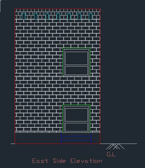
- Projections are drawn in north direction and final image is as follows
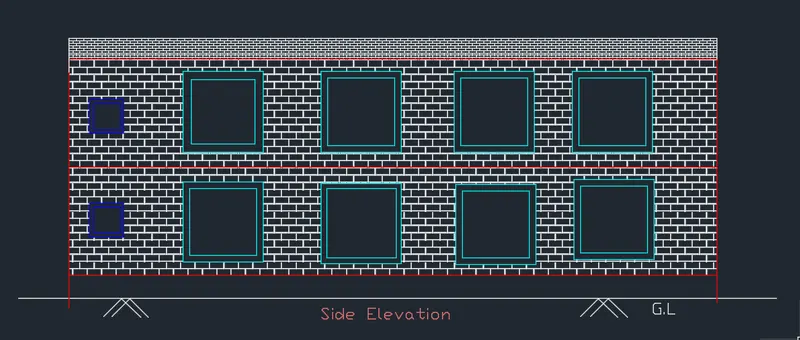
- Project the outer line for the sections in both East and North directions
- Make offsets and draw parapet wall of 2'
- Trim unwanted lines
- The final image of Section AA is as follows
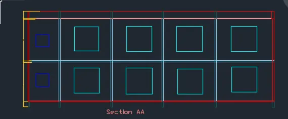
- The lines are projected in east direction
- Draw staircase using drafting tools
- Trim unwanted lines
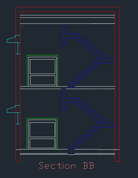
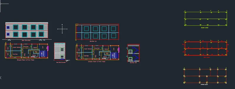
- The final image of Architectural drawing (Plan, Elevation, Section) are as follows
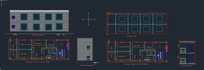
- To draft structural drawing we need to freeze remaining all the elements
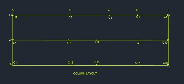
- Freeze all elements except Columns and name the column numbers
- The final image of Column layout are as follows
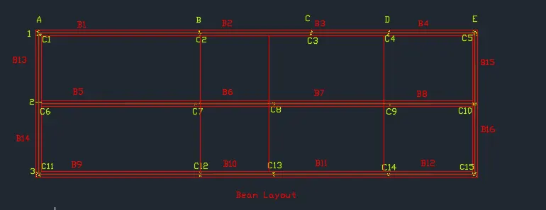
- Freeze all elements except external lines and centreline
- Name the beam numbers for it
- The final image of beam layout are as follows
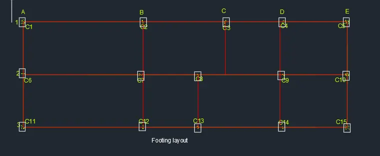
- Freeze all elements except centreline
- Draw a rectangle on the column
- The final image of footing layout are as follows
Result: Residential building was designed and drafted with given specifacations and with East facing orientation.
Architectural drawing and structural drawing was designed using drafting tools in the AutoCAD software.
The final image of Residential building are as follows
https://web.autocad.com/acad/me/sid/shares/drawings/92f910d9-3163-47a4-aed8-e6e28b5cdd39/editor
CHALLENGE ACCOMPLISHED