Project 1 _Creating an Architectural plan for the provided plot size and develop relevant basic structural drawings
QUE:-
Design and Draft a layout of a residential building with the following details:
a. Plot Size: 60’x20’(18.3m x6m)
b. Orientation- Facing East
c. Develop the following: 1. Architectural Drawing (Floor Plan, Elevations, and Sections) 2. Structural Drawing (Column, Bean, Footing Plan)
AIM:- TO CREATE ARCHITECTURAL DRAWINGS AND STRUCTURAL DRAWINGS IN GIVEN PLOT SIZE.
FLOOR PLAN ,ELEVATION AND SECTIONS ARE INCLUDED IN ARCHITECTURAL DRAWING. COLUMN ,BEAM ,FOOTING PLAN
ARE INCLUDED IN STRUCTURAL DRAWING.
COMMAND USED IN DRAWING:-
- line
- offset
- layer
- qleader
- copy
- move
- trim
- limits
- dimstyle
- style
- divid
- extend
PROSEDURE FOR ARCHITECTURAL DRAWING :-
- first we have to open autocad and set the limits and units to architectural .
- in the que they give plot size of 60'x20'.
- so we have to draw plot with this dimension using line command.
- draw plot area and give dimension to them with diferent layer and colour.
- on upper side give direction to the north.
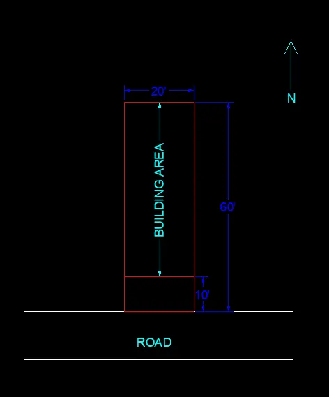
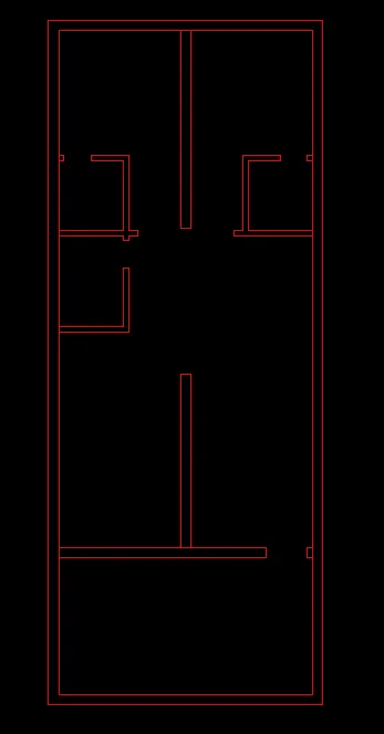
- now we have to draw a floor plan.
- for the floor plan we have to give offset to outer wall of 9".
- now we draw bedroom on the top of both side with the dimension of 8'11"x14'8" .
- all the inner wall are with the 4.5" thickness.
- now we have to draw two toilet in two bedroom.
- dimension of that two toilet is 4'8"x5'1".
- now draw the kitchen 8'11"x15'9".
- remove all unnecesary part by using trim command.
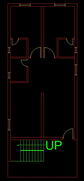
- now its time for doors ,windowsand stairs
- for doors and windoes assume the size andgive diferent layer to them.
- same for stairs assume the size .
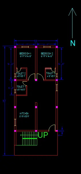
- for the column size all column are 9'x9'.
- now using proper dimension method give dimension to plan and write all required text in the drawing.
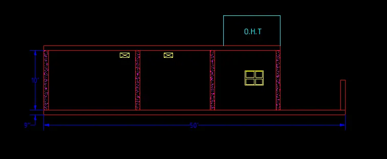
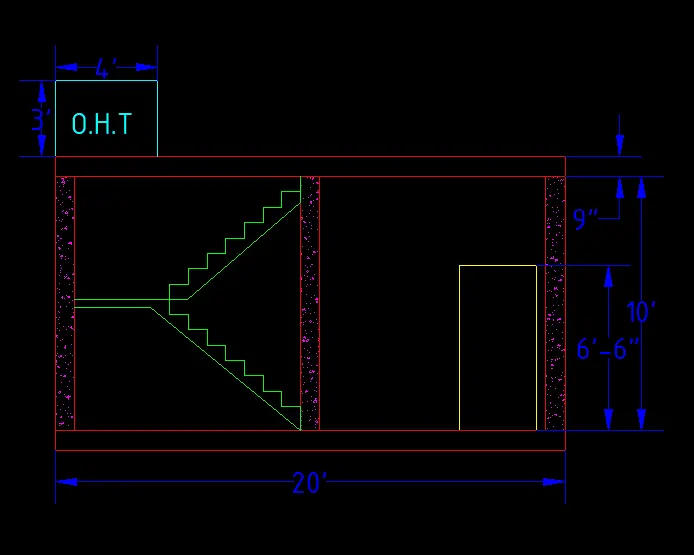
- now we have to give side elevation from the left side and from the front side.
- using xline command take a reference point from the plan and give the side elevation.
- size of column is 10'.
- on the top draw O.H.T of 6x4x3.
- same as above method draw front elevation using xline coomand.
PROSEDURE FOR STRUCTURAL DRAWING :-
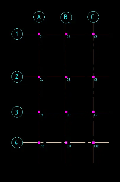
- in the structural drawing we have to draw column plan,beam plan and footing plan.
- first for the column plan take xline command and take point from the architectal plan.
- using diferent layer and diferent line tipe we draw all center line as we required.
- using text command give name to every column by its layer.
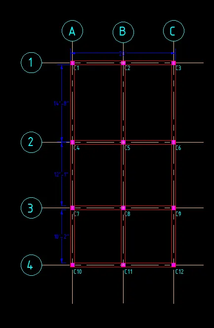
- now for beam plan we have to just connect the column plan with line.
- give the dimension using dimension tool.
- now for footing plan draw footing around the column with the dimension of 4'6"x4'6".
- draw every footing at every column nd give diferent layer tho them.
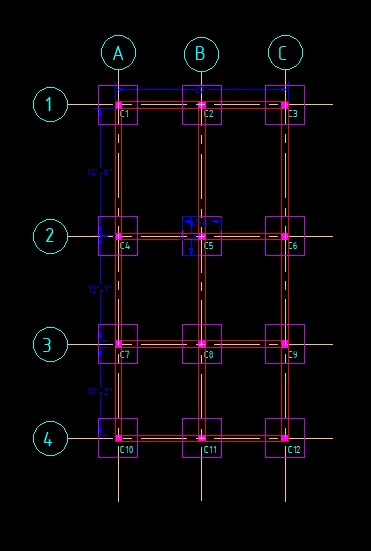
RESULT :- ALL ARCHITECTURAL AND STRUCTURAL DRAWINGS ARE DRAWEN ON AUTOCAD.