Project 1 _Creating an Architectural plan for the provided plot size and develop relevant basic structural drawings
1.
Plot Size: 60’x20’(18.3m x6m)
Orientation- Facing East
Develop the following: 1. Architectural Drawing (Floor Plan, Elevations, and Sections) 2. Structural Drawing (Column, Bean, Footing Plan)
aim:
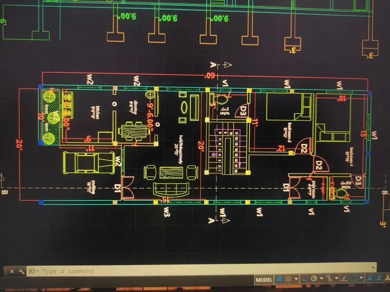
to draw floor plan for 20'*60'
tools were used :
- Line
- Circle
- Rectangle
- Polyline
- Trim
- Extend
- Copy
- Mirror
- Rotate
- Erase
- Offset
- Move
- Array
Scale,Fillet
explode
procedure :
draw the rec for x=20'
draw the rec for x=60'
to make the area of the resident building
and take offset to create the room area based on our assumption
doors:
D1-4' which is for main door and puja room
D2-3' which is for bedroom
D3-2'6" which is for bathroom
opening
O-3'which is for dinning/kitchen
make trim the unnecessary lines for door in particular area
create a door using line and start end direction arc , at 3'width and along with that panel is attached over there
and i attach the door where in particular gaps which have been i made
windows:
W1-5' which is for bedroom
W2-4' which is for kitchen
W3-6' which is for hall
ventilator:
V1- 2' which is for bathroom/puja
make the windows and venti using rec and line tool to attach the respected area
layer prop:
need to create the layaers for the each elements which is wall , int wall , window door etcc...
it is used for knowing the seperate element and we use this layer to hide the element , lock the element for the
editing purpose .
colour :
even though we can use layer pr to seperate the elements but colour is for visiblity purpose we could just see and
we ve just found out whatever element is it ..
tool pallet :
it is an architectural purpose we just attach some furniture by using this tool to make the drawing beautiful and for the client clarification
stair case
tread=1'
riser=6.7"
waist slab 5"
no of steps=18steps
no of tread=17 coz last one is consider as a landing so we wouldn't mention that.
column :
basic column C=9"*9"
first attach at four corner of the building after we could just attach column ,based on our structural experience to attach the rest columns
dimension :
linear dim is used to show the area s dim for clarification
make the section line on both x and y direction AA and BB including stair
these type of tools i been used here to make these 20*60' floor plan whereas the given below i ve been draft the
section column marking etc..
result :
aim :
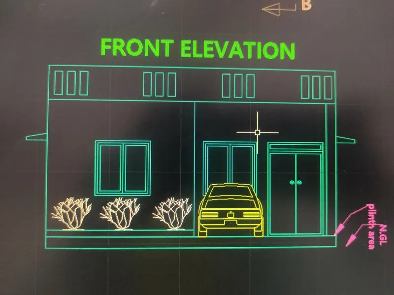
to draw the elevation for the respected floor plan
tools been used :
- Line
- Circle
- Rectangle
- Polyline
- Trim
- Extend
- Copy
- Mirror
- Rotate
- Erase
Offset
move
procedure:
draw x line which is a conctruction line which is work as a ref line to draw the section elevation etc..
first x line is drew through the floor plan to draw the elevation
first draw the door windo using rec tool
trim the unnecessaary line to make the drawing good
copy is used for create the same element
add tp for archi pusrpose
create the sunshade using line
aim :
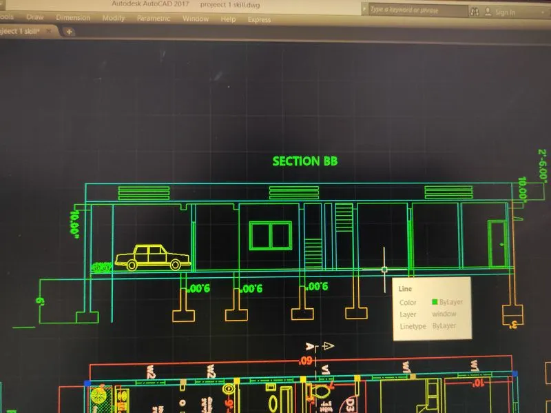
to draw the section BB for the respected floor plan
tools been used :
- Line
- Circle
- Rectangle
- Polyline
- Trim
- Extend
- Copy
- Mirror
- Rotate
- Erase
Offset
move
procedure:
draw the section for BB
here draw the ray line it is consider as a construction line
draw the ray as a ref line to draw the sec BB
first draw visible windows and doors next beam is attach on the column area
and footing should be drawn straight to the column footing is 3'6"
tp is attached for archs purpose
parapett is attached by using line tool which is 2'6"
copy to draw the same footing for all the straight column
m text is used to show the what kind of drawing it is
result:
aim :
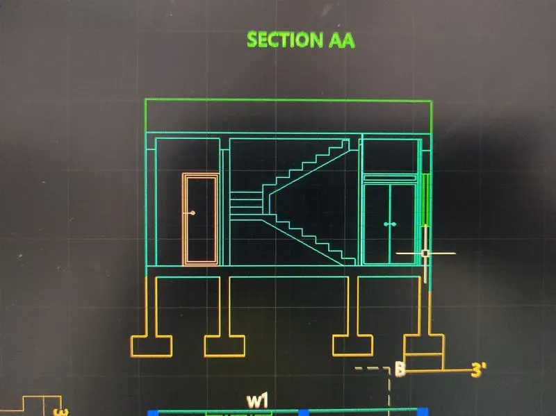
to draw the section AA for the respected floor plan
tools been used :
- Line
- Circle
- Rectangle
- Polyline
- Trim
- Extend
- Copy
- Mirror
- Rotate
- Erase
Offset
move
procedure:
draw the section for AA
here draw the ray line it is consider as a construction line
draw the ray as a ref line to draw the sec AA
first draw visible windows and doors next beam is attach on the column area
and footing should be drawn straight to the column footing is 3'6
parapett is attached by using line tool which is 2'6"
copy to draw the same footing for all the straight column
m text is used to show the what kind of drawing it is
aim :
to draw the section footing plan for the respected floor plan
tools been used :
- Line
- Circle
- Rectangle
- Polyline
- Trim
- Extend
- Copy
- Mirror
- Rotate
- Erase
Offset
move
proceddure:
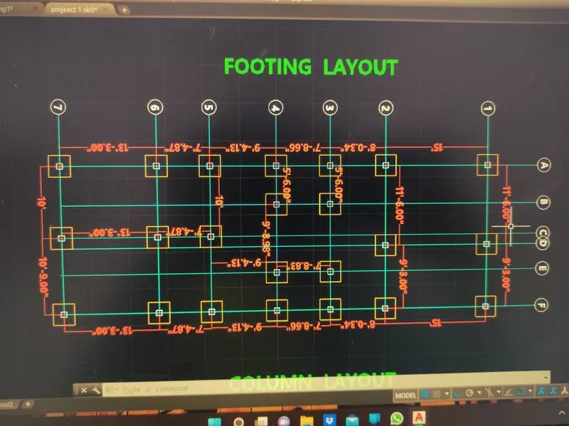
take xline as ref line to make grid line for mark footing
x is consider as abc whereas y is cons as a 123
footing - 3'*3'
the footing will attach on the intersect grid lines
attach all intersect lines I.E 1and a intersect line is a first footing
copy if the all footing is as same size
dim is used here to show the centre to centre between the each footing
aim :
to draw the section footing plan for the respected floor plan
tools been used :
- Line
- Circle
- Rectangle
- Polyline
- Trim
- Extend
- Copy
- Mirror
- Rotate
- Erase
Offset
move
procedure:
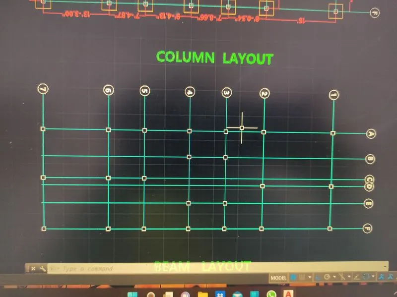
take xline as ref line to make grid line for mark footing
x is consider as abc whereas y is cons as a 123
column-9"*9"
the footing will attach on the intersect grid lines
attach all intersect lines I.E 1and a intersect line is a first column
copy if the all column is as same size
dim is used here to show the centre to centre between the each column
result:
aim :
to draw the section footing plan for the respected floor plan
tools been used :
- Line
- Circle
- Rectangle
- Polyline
- Trim
- Extend
- Copy
- Mirror
- Rotate
- Erase
Offset
move
procedure:
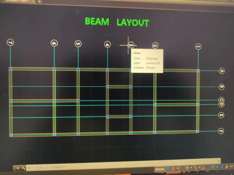
take xline as ref line to make grid line for mark footing
x is consider as abc whereas y is cons as a 123
roof beam-9"*10"
lintel beam-9"*9"
plinth beam -9"*10"
slab thick ness 5"
the beam will attach on the column top face
copy if the all beams are in same size
result:
conclusion: In the architectural and structural drawaing 20'*60' are face at the east and the arch draw and structural drawing is now completed