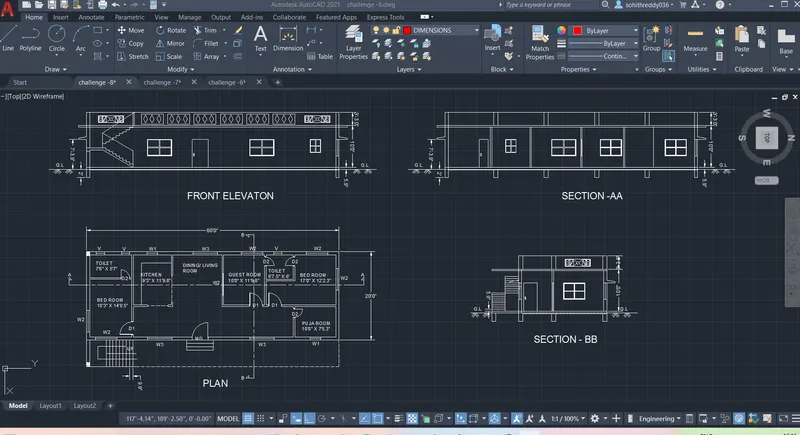
Project 1 _Creating an Architectural plan for the provided plot size and develop relevant basic structural drawings
AIM : To Design and Draft a layout of a residential building with the given details & to develop the architectural drawing ,structural drawings.
INTRODUCTION:
AutoCAD offers various tools to perform different tasks. The various tools which are used for drafting in this project are briefly described here. These draw tools include: - line,Construction line,rectangle,polygon,polyline,circle,elepse etc.
1. Rectangle - Command used is REC. It can also evoked from ribbon, toolbar, tool pallettes. Follow the commands in AutoCAD to complete the rectangle. Different ways by which rectangle can be drawn are:
- Drawing rectangle by specifying two opposite corners.
- Drawing rectangle by specifying area an one side length.
- Drawing rectangle by specifying their dimension.
- Drawing rectangle at an angle.
- Drawing using different options like chamfering, fillets, width, thickness, elevation.
2. Regular polygon - Command used is POL. Other ways of evoking the tool is through ribbon, tool bar and tool pallettes. This tool is used to make a polygon with minimum of 3 sides and a maximum of 1024 sides. Different ways of drawing polygon is:
- Drawing a polygon by specifying the centre of the polygon:
- Drawing an inscribed polygon using centre of polygon option.
- Drawing a circumscribed polygon using the centre of polygon option.
- Drawing a polygon by specifying the edge.
3. Polyline - Command used is PLINE or PL and is also evoked through ribbon, toolbar, tool pallettes. There are two types of polyline: 2D and 3D. Different options in polyline includes arc, halfwidth, length, width. It is possible to switch between an arc and line anytime in between the drawing.
Polyline is a very important tool in utility drawing like pipelines, sewage lines etc.
4.CONSTRUCTION LINE.
Construction lines (also known as xlines) are temporary line work entities that can be used as references when creating and positioning other objects or line work. Construction lines are either circles or straight lines that extend to infinity in both directions.
The following prompts are displayed.
Select line work under cursor
Specify the line on which we want to base our construction line.
Enter to select points
- Specify a point to define the root of the construction line.
- Specify a second point through which the construction line should pass.
5.LINE:
The command used is L. The line object is the most basic and common object in AutoCAD drawings of any discipline.Each segment is a line object that can be edited separately, assigning properties such as layer, linetype, and lineweight. The simplest method to draw a line is to click two locations in the drawing area.
6.CIRCLE:
Command used - CIRCLE or C.Creates a circle based on a center point and a radius or diameter value. It consist of different types of methods to draw as mention below.
- Center, Radius
- Center, Diameter
- 2 - Point
- 3 - Point
- Tan, Tan, Radius
- Tan, Tan, Tan
There are various modification tools in AutoCAD which are used to modify the sketched objects and these includes move, copy, offsetting, rotating, Scaling of sketched objects, filleting, chamfering etc.
Chamfer: A bevel or chamfer is-
- an angled line that meets the end-points of two straight 2D points.
- a sloped transition between two surfaces or adjacent faces on a 3D solid.
The distances and angles that we specify are applied in the order taht we select the objects.
Fillet: A round or fillet is-
- an arc that is created as tangent between two 2D objects.
- a curved transition between two surfaces or adjacent faces on a 3D solid.
Offset: It is used to create concentric circles, parallel lines and parallel curves.
Object Snap: Object snap provide a way specify precise locations, such as endpoint, mid-point etc., on objects whenever we are prompted for a point within a command.We can offset an object at a specified distance or through a point.
Rotate: This tool rotates object around a base point. An object can be rotated either by entering the angle of rotation, or drag the object around its base point and specifying a point location to which we want to rotate the object to. We can also enter c to create a copy of the selected objects, or enter r to rotate the selected objects from a specified reference angle to an absolute angle.
Copy: This command copies objects at a specified distance in a specified direction. With the COPYMODE system variable, we can control whether multiple copies are to be created automatically.
Move: It moves objects a specified distance in a specified direction. We can use coordinates, grid snaps, object snaps, and other tools to move objects with precision.
Mirror: This command is used to create a mirrored copy of selected objects. Using this command we can create objects that represent half of a drawing, select them, and mirror them across a specified line to create the other half.
Trim: It trims objects to meet the edges of other objects. There are two modes that can be used to trim objects, viz. Quick mode and Standard mode.
Extend: This command extends objects to meet the edges of other objects. To extend objects, we first need to select the boundaries, and then press Enter and select the objects that we want to extend. To use all objects as boundaries, we press Enter at the first Select Objects prompt.
Join: It joins the endpoints of linear and curved objects to create a single object. A series of finite linear and open curved objects at their common endpoints are combined to create a single 2D or 3D object. The resulting object depends on the types of objects selected, the type of object selected first, and whether the objects are coplanar
hatch : it is a command to fill the emty objects kind of any symbols of materials , masonrys etc.
ADC - architectural design center for furniture blocks and etc.
LAYERS
Use layers to control the visibility of objects and to assign properties such as colour and line type. Objects on a layer normally assume the properties of that layer. However, you can override any layer property of an object. For example, if an object’s colour property is set to BYLAYER, the object displays the colour of that layer. If the object’s colour is set to Red, the object displays as red, regardless of the colour assigned to that layer.
Command used- LAYER
SPECIFICATIONS :
a. Plot Size: 60’x20’(18.3m x6m)
b. Orientation- Facing East.
Assumed measurements :
- the column size as 9" x 12" mm & take beam size is also same,
- exterior wall thickness is 9",interior wall thickness is 4.5" and
- the staircase rise = 5.9" & thread = 9.9"
- Main door (MD) = 4' X 6'10"
- D1 = 3'3" X 6'10"
- D2 = 2'3" X 6'10"
- W1 = 2'7" X 3'3"
- W2 = 5'3" X 4'0"
- W3 = 6'0" X 4'0"
- V = 2'0" X 2'0"
PROCEDURE :
1.First open the auto cad software & create a template file in the folder.
2.prepare the drawing sheet as comfotable as like you by setting up & start up.
3.Before the start of drawing in auto cad, prepare the plan drawing in paper with line diagram . and also the plan was designed and followed by according to the vastu satra.
4. First we draw the architectural plan by create the wall lines in the plan with using the line ,x line,or polyline commands.
5.use off set command as per the assumed or given dimesions for easy drawing & trim the extra lines using trim command.
6.change the line type in the bylayer option, to ACAD_ISO03W100 type.set the line type scale as per drawing.
7.hatch the filled portions with hatch command.
8.use modification tools such as with trim,mirror,copy ,join ,explode ,fillet,multi leader commands.
9.Type the text with M text command ,and set the text Height of as per drawing.
10.draw the dimensions by using the dimension tool DIM .
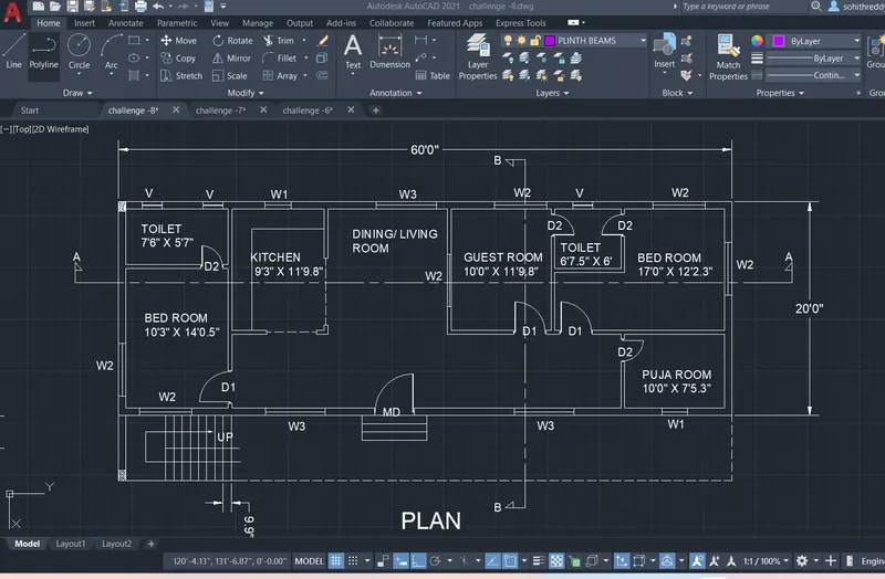
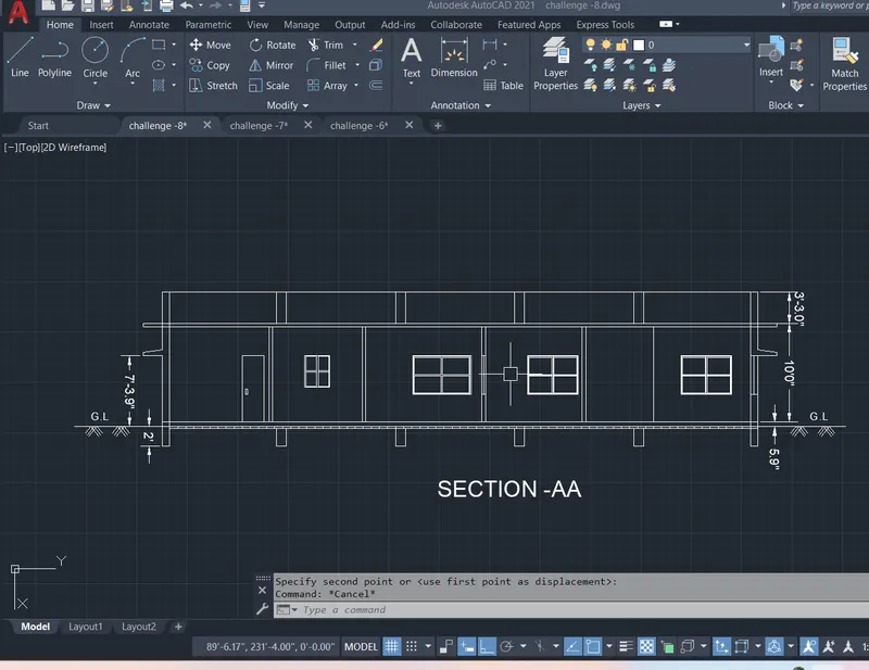
11. next we draw the section -AA , by extending the refarence lines from plan.
12.use off set command as per the given dimesions . for easy drawing & trim the extra lines using trim command.
13.change the line type of the stair railing in the bylayer option, to ACAD_ISO03W100 type.set the line type scale as per drawing.
14.use midification tools such as with trim,mirror,copy ,join ,explode ,fillet , multie leader commands.
15.Type the text with M text command ,and set the text Height of as per drawing.
16.draw the dimensions by using the dimension tool DIM .
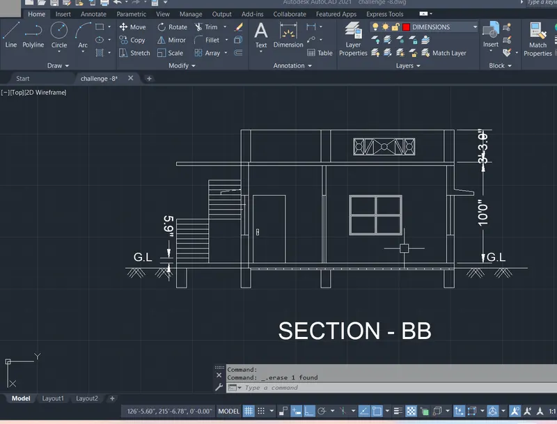
17. next we draw the section -BB ,by extending the refarence lines from plan.
18.use off set command as per the given dimesions . for easy drawing & trim the extra lines using trim command.
19.use midification tools such as with trim,mirror,copy ,join ,explode ,fillet,multie leader commands.
20.Type the text with M text command ,and set the text Height of as per drawing.
21.draw the dimensions by using the dimension tool DIM .
22. next we draw the elevation from the coy of section AA , by extending the refarence lines from plan.
23.use off set command as per the given dimesions for easy drawing & trim the extra lines using trim command.
24.change the line type of the stair railing in the bylayer option, to ACAD_ISO03W100 type.set the line type scale as per drawing.
25.use midification tools such as with trim,mirror,copy ,join ,explode ,fillet , multie leader commands.
26.Type the text with M text command ,and set the text Height of as per drawing.
27.draw the dimensions by using the dimension tool DIM .
28. create the blocks bt block command & insert the blocks from insert command.
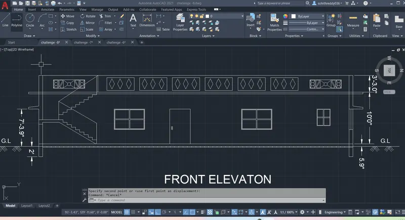
29.Next we draw structural drawings like column beam footing plans.
30.take the column size as per assumed measurements.
31. draw the center lines with dashed line type.
32.draw the plinth beams,along with coloumns by using rectangle command.
33.hatch the filled portions of coloumns by using hatch command.
34.create the layers seperatly arrange the objects into individual layers.
35.draw the dimensions by using the dimension tool DIM .
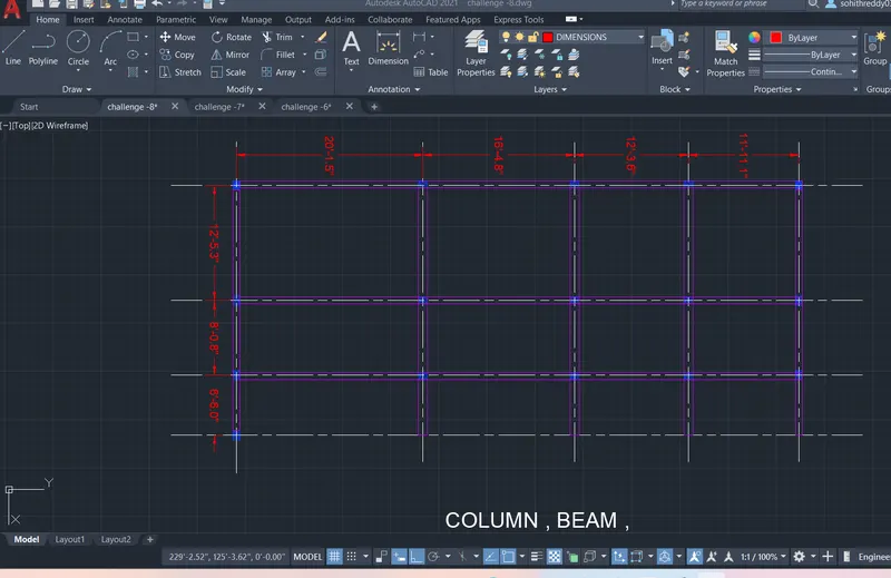
36.Next we draw the footings around the columns .
37.create the layer seperatly arrange the objects into individual layers.
38.draw the dimensions by using the dimension tool DIM .
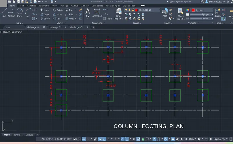
39.take a snap of overall structural drawing plan.
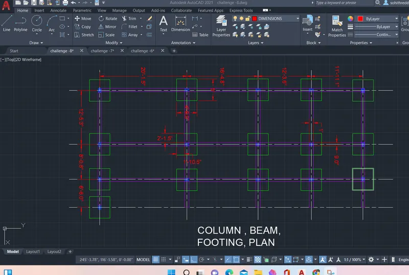
40.save the completed drawing file ctrl+ s . & take a snap of drawing upload it in the results.
FINAL RESULTS :
- The architectural drawing ,structural drawings are drwan by using AutoCad.
- Drawn figures PLAN ,SECTION -AA,BB,Front Elevation,column,beam,footing plans are uploded in the above, as a picture.