Project 1 _Creating an Architectural plan for the provided plot size and develop relevant basic structural drawings
AIM:
To design and draft a layout of a residential building and develop the architectural drawing for floor plan, elevation and section by using drafting tools in AutoCAD.
INTRODUCTION:
Plot Size: 60’x20’ (18.3m x6m)
Orientation- Facing East
Develop the Architectural Drawing (Floor Plan, Elevations, and Sections)
Plan, Section and Elevation are different types of drawings used by architects to graphically represent a building design and construction.
- A plan drawing is a drawing on a horizontal plane showing a view from above
- An elevation drawing is drawn on a vertical plane showing a vertical depiction.
- A section drawing is also a vertical depiction, but one that cuts through space to show what lies within.
FLOOR PLAN:
Floor plan drawings are a specific type of drawing architects use to illustrate a building or portion of a building. A plan is drawn from a vertical plane looking down from above. Plan is often used to depict the layout of a building, showing locations of rooms and windows, walls, doors, stairs etc.
Floor plan is a technical drawing to scale, showing a view from above of the relationships between the rooms, spaces, traffic patterns and their physical features at one level of a structure.
ELEVATION:
Elevation drawings are a specific type of drawing architects use to illustrate a building or portion of a building. An elevation is drawn from a vertical plane looking straight on to a building façade or interior surface. This is as if you directly in front of a building and looked straight at it.
Elevations are a common design drawing and technical architectural or engineering convention for graphic representation of architecture. Elevation drawings are orthographic projections means they are not drawn in perspective and there is no foreshortening.
SECTION:
Section drawings are a specific type of drawing architects use to illustrate a building or portion of a building. A section is drawn from a vertical plane slicing through a building this is as if you cut through a space vertically and stood directly in front looking straight at it.
Sections are common design drawing and technical architectural or engineering convention for graphic representation of architecture. Section drawing are orthographic projections means they are not drawn in perspective and there is no foreshortening.
PROCEDURE:
Column size: 250mm x 250mm
External wall thickness: 250mm
Internal wall thickness: 125mm
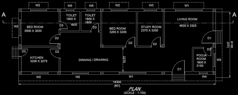
FLOOR PLAN: -
STEP-1:
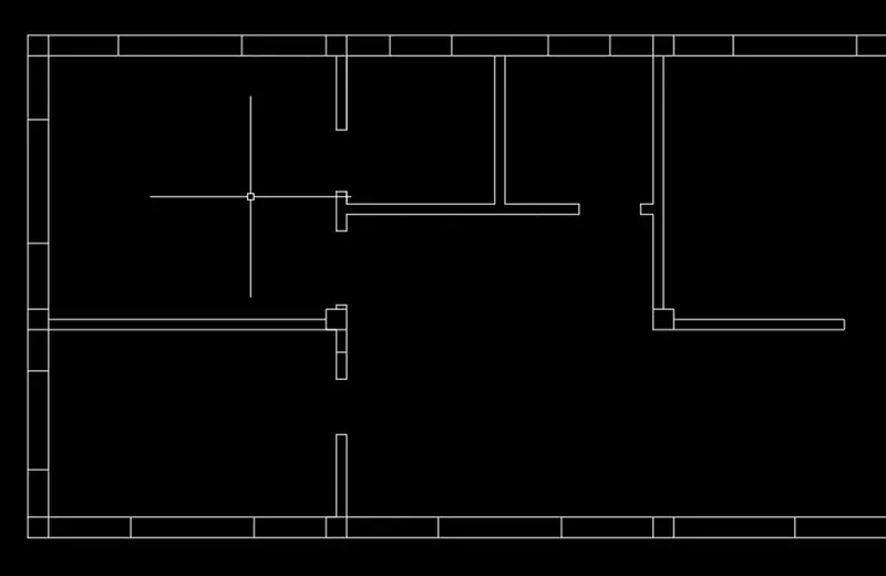
- First, we take the command XLINE, draw the horizontal and vertical lines.
- Then use the command OFFSET, draw the thickness of external wall and draw the interior walls of the plan as per given dimensions.
- Use the command LINE and columns where there are required.
- Use the command TRIM and erase the all the external excessive lines.
- After completion of external walls, now we have to sketch the interior walls properly as per given dimensions by using the command LINE.
- After completion of interior walls, now we have to sketch the space for doors, windows, ventilators as per given dimensions by using the command LINE.
- Use the command TRIM to create the space for doors.
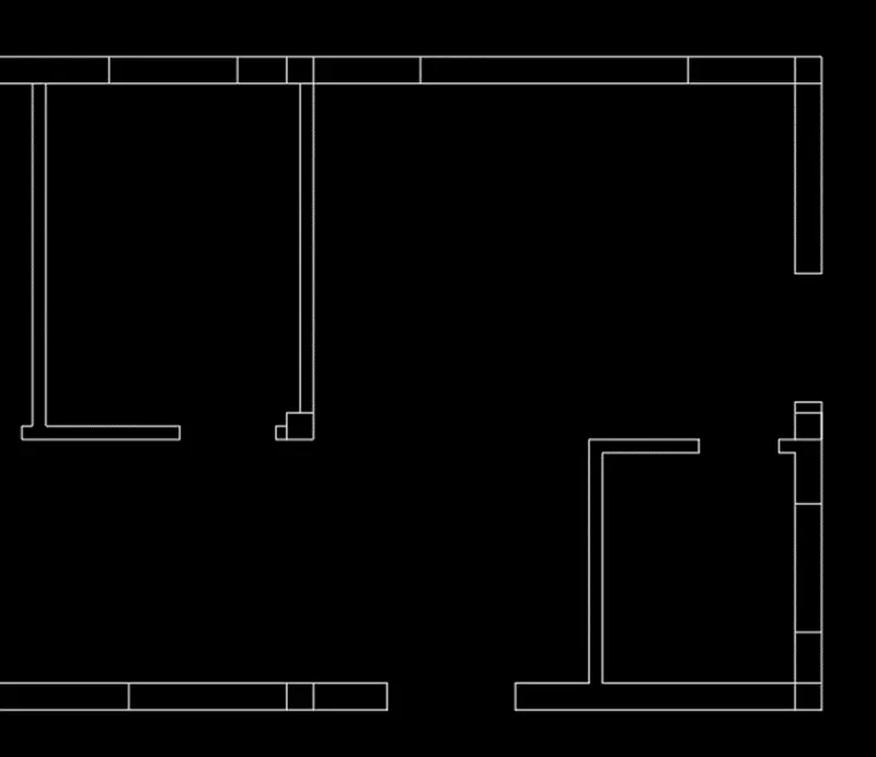
- After completing the sketch of the first part, the procedure is followed for second part of plan.
- To draw the interior walls and to sketch the space for doors, windows, ventilators as per given dimensions by using the command LINE.
- To sketch staircase, we use command OFFSET, command LINE to complete the works.
- After complete the sketch, use command TRIM to erase the unwanted lines and crate the space for doors.
STEP-2:
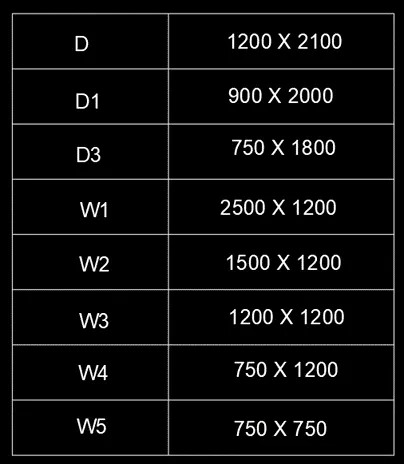
- After completing the sketch of the plan, we should have to give the text, dimensions to the plan.
- Firstly, give the dimensions for the plan and representing them by using command
- Then place the text between the lines as table by using the command
- After that use the command MOVE to place the sketch between the table.
- Select the command LINE, command OFFSET to complete the sketching of doors, windows and steps near the doors as per the dimensions.
- Select the command CIRCLE to complete the sketching of doors.
- Select the command HATCH for highlighting the columns where they placed by using the pattern AR-CONC.
- Use layer properties to draw the sunshade by using the layer continue. as for sunshades and section defining lines (AA, BB) for proper understanding.
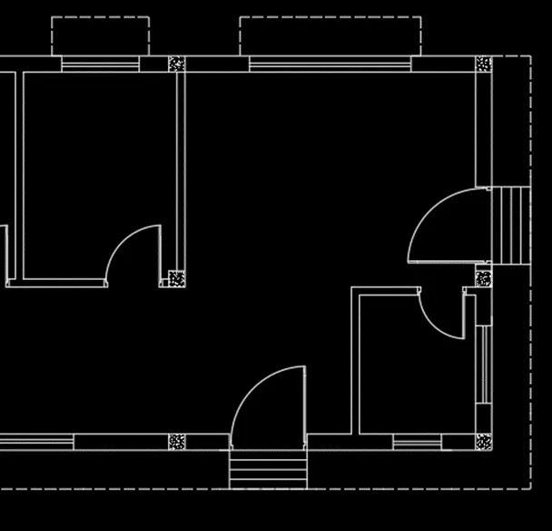
- Continue the same procedure for completing the sketching of doors, windows and steps for entire plan.
- After completed the sketch of all the parts of plan, then we have to label and give dimensions to them.
- Use layer properties to draw the section line (AA) by using the layer continue for proper understanding.
- Select the command DTEXT and labelling the plan as per required places as rooms, toilets, doors, windows, ventilators etc.
- Use command DIMLIN to specify the dimensions by using the options Continue and Baseline for required dimensional specifications.
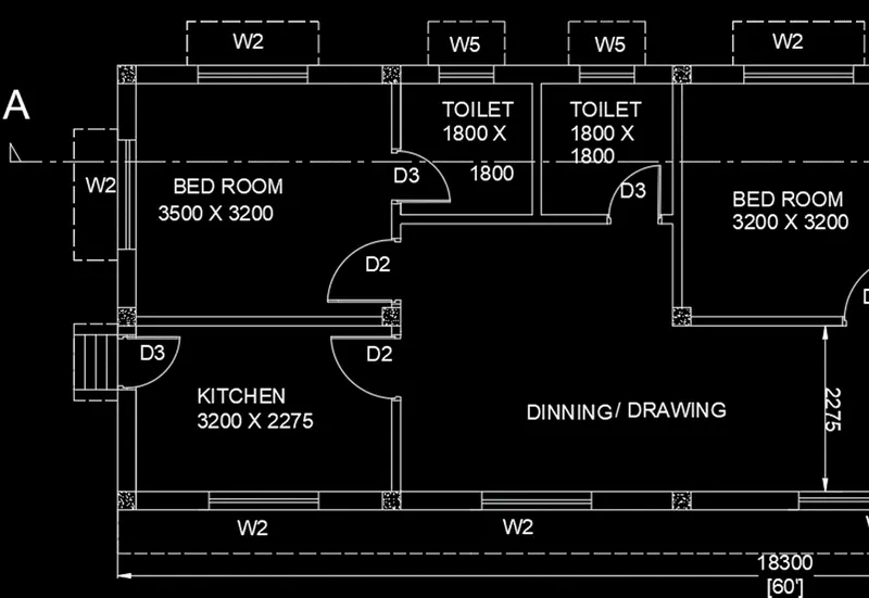
- Continue the same procedure for complete the labelling for entire plan.
ELEVATION: -
STEP -1:
- Sketching elevation of a building is takes place after the completing the plan of building.
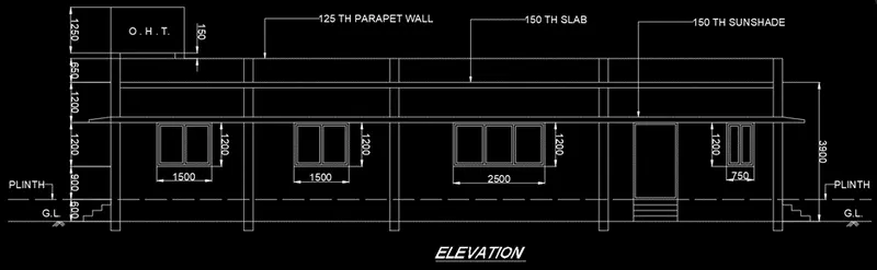
- To draw the elevation, we should extend the vertical lines from the plan by using the command XLINE at every corner, columns, windows and doors.
- using the command XLINE draw the horizontal line.
- Select the command OFFSET and draw the parallel lines for the mentioned horizontal line for plinth level, sill level, lintel level, slab level, parapet wall level etc.
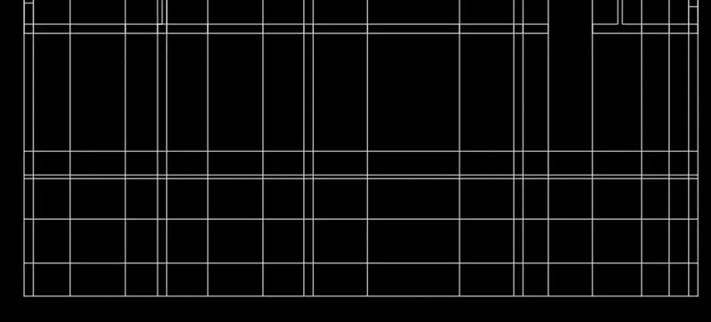
- Use the command TRIM to eliminate the unwanted lines to show the sketch of windows, doors, columns etc.
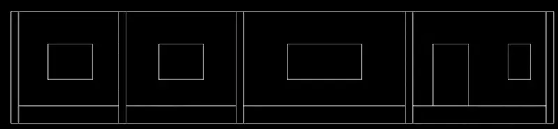
STEP-2:
- After completing the outer sketch of windows, doors, columns etc, we should draw the remaining parts of the building.
- Using the command LINE to sketch the parapet wall height, slab height and slab thickness, sunshade, steps.
- Select the command OFFSET to draw the steps and decorate the windows.
- For plinth level, use the layer properties to create a new to layer to represent the plinth level.
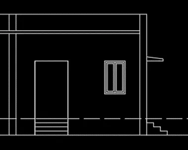
- Continue the same procedure for complete the doors, steps and elevation of the building.
STEP-3:
- Use the command LINE to sketch the sunshade and overhead tank.
- Select the command DTEXT for labelling the elevation.
- Use command DIMLIN to specify the dimensions by using the options Continue and Baseline for required dimensional specifications.
- By using the command LEADER to represent the building materials.
- Use the command TRIM to eliminate the unwanted lines.
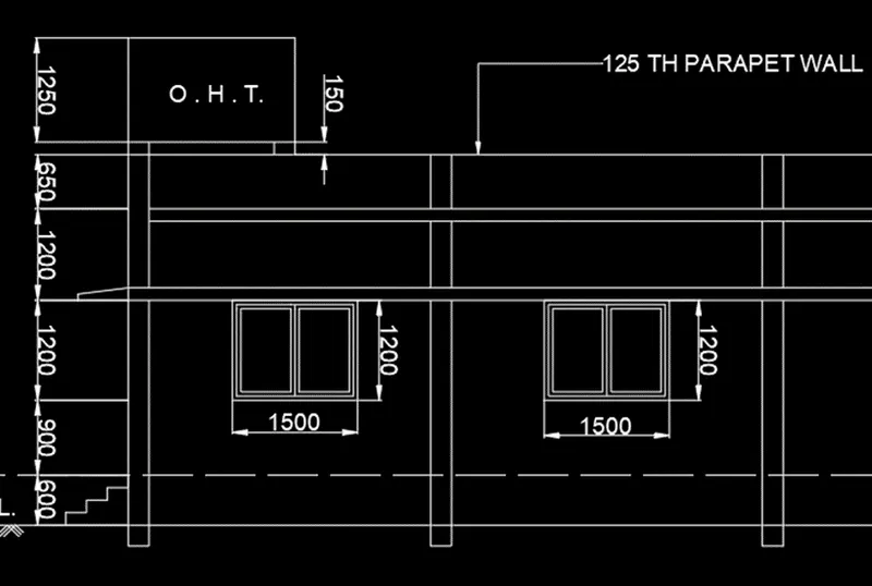
- Continue the same procedure for complete the elevation of the building.
SECTION (AA): -
STEP-1:
- After completing the plan and elevation now we have to sketch the section of the building.
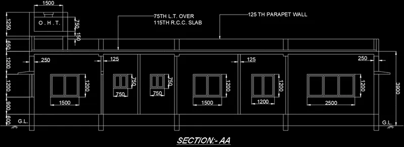
- To draw the section, we should extend the vertical lines from the plan by using the command XLINE at every corner, columns, windows and doors.
- using the command XLINE draw the horizontal line.
- Select the command OFFSET and draw the parallel lines for the mentioned horizontal line for plinth level, sill level, lintel level, slab level, parapet wall level etc.
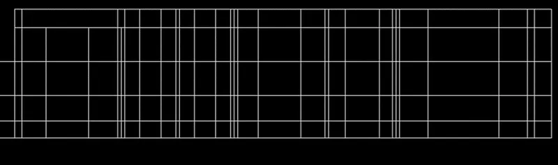
- Use the command TRIM to eliminate the unwanted lines to show the sketch of windows, doors, columns etc.
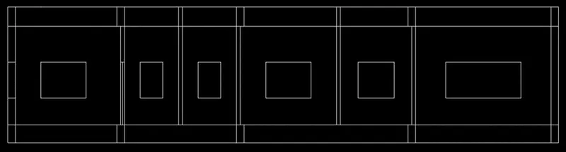
STEP-2:
- After completing the outer sketch of windows, doors, columns etc, we should draw the remaining parts of the building.
- Using the command LINE to sketch sunshade and the section of doors, windows.
- Select the command OFFSET to decorate the windows.
- For plinth level, use the layer properties to create a new to layer to represent the plinth level.
- Use the command TRIM to eliminate the unwanted lines.
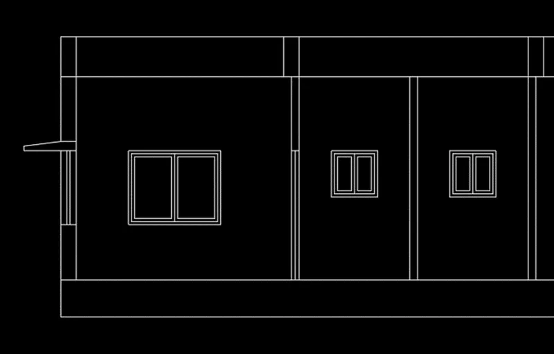
- Continue the same procedure for complete the section of the building.
STEP-3:
- Use the command LINE to sketch overhead tank.
- Select the command DTEXT for labelling the elevation.
- Use command DIMLIN to specify the dimensions by using the options Continue and Baseline for required dimensional specifications.
- By using the command LEADER to represent the building materials.

- Continue the same procedure for complete the section of the building.
RESULT:
AIM:
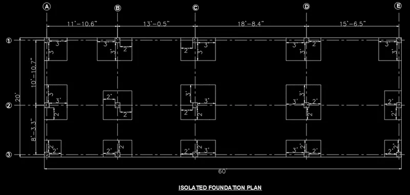
To draw the layout and develop the structural drawing for the columns and footing plan by using the drafting tools in AutoCAD.
INTRODUCTION:
a.Plot Size: 60’x20’ (18.3m x6m)
b. Orientation- Facing East
c.Develop the Structural Drawing (Column, Beam, Footing Plan)
COLUMN:
Column is a compressive member and vertical element structure that supports the beam and slab. Column transmits the load from beams and slabs to the floor or foundation.
Columns are designed to resist lateral forces and all columns are connected to footing at the bottom point. In case of column is rested on the beam then it is called floating column.
BEAM:
Beam is a horizontal member that transfers the load to the column or wall which in turn gets transferred to the foundation. Beams are designed to with stand vertical loads, shear force and bending moment.
Load applied to the beam result in rection forces at the supports points of the beam, the total effect force produce on the beam is shear force and bending moment with in the beam that in turn and induce the internal stress, strain and deflection in the beam.
FOUNDATION:
Foundation is also termed as footing and are the critical part of the structure. Footings are designed to transmit the load to the soil evenly with out exceeding the safe bearing capacity and minimize the distress against the soil movement and keeps the building or structure stable and secure.
For small residential building we use normally shallow foundation isolated footing.
Isolated footing:
Isolated footing is a simplest form of foundation used worldwide depends upon the soil type. Isolated footing or single footing are structural elements used to transmit and distribute loads of single column to the soil with out exceeding its bearing capacity and in addition to preventing excessive settlements and providing adequate safety for sliding and over turning.
PROCEDURE:
Column size: 250mm x 250mm
Footing used: Isolated Pad Footing
STEP-1:
- First step is to select the command XLINE and draw the one horizontal line and one vertical line.
- Use the command OFFSET draw the parallel lines horizontally and vertically as per the given dimensions.
- Select the layer properties to create a Layer as grid lines and give the line type as

- Use the command TRIM to eliminate the unwanted lines.

STEP-2:
- After completing the drawing of grid lines as per the dimensions. Now we have to sketch the columns and isolated foundation.
- Select command LINE and draw the outer layer of the plan.
- Use the command DTEXT to represent the grid lines as A, B, C… and 1, 2, 3….
- select the command CIRCLE to place the text of representing grid lines between the circles.
- Use the command LINE and draw the columns.
- Use the command TRIM and eliminate the unwanted lines.
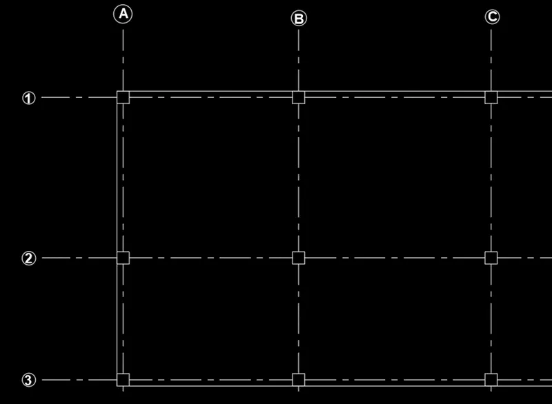
- Continue the same procedure for completing the entire layout.
STEP-3:
- After completing the layout plan, now we have to complete the remaining work.
- Now we have to draw the isolated footing plan at specified places as per the dimensions.
- Use the command LINE to draw the footing around the column.
- Then use the command HATCH and select the pattern AR-CONC for representing the columns.
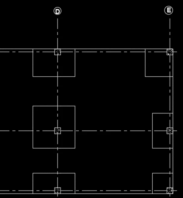
- The same procedure is continued for completing the layout.
STEP-3:
- Use the command DIMLIN and specify the dimensions by using the option continue.
- Then use the command DTEXT for labelling the plan.
- Use the command TRIM and eliminate the unwanted lines.
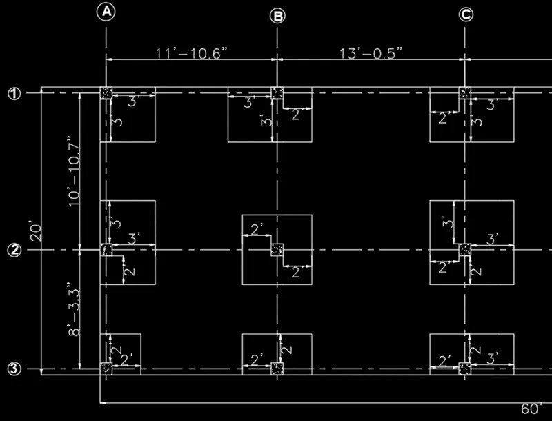
- The same procedure is continued for completing the layout.
RESULT: