Project 1 _Creating an Architectural plan for the provided plot size and develop relevant basic structural drawings
PROJECT
DESIGN AND DRAFT A LAYOUT OF A RESIDENTIAL BUILDING
a. Plot Size: 60’x20’(18.3m x6m)
b. Orientation- Facing East
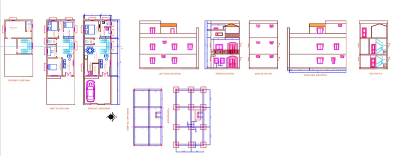
c. Develop the following: 1. Architectural Drawing (Floor Plan, Elevations, and Sections) 2. Structural Drawing (Column, Beam, Footing Plan)
AIM:
To draw residential building of dimensions 60' x 20’ with the following drawings
- Architectural drawing plot drawing ground floor plan first floor plan elevation view
- Structural drawing section view footig layout column layout beam layout
OBJECTIVE:
Providing with all facilities for the residential building, it it includes portico, dining & drawing hall, kitchen, bed room, study room, guest room, balcony, staircase with passage, path & w.c with proper specification.
INTRODUCTION:
A building is the process of transferring architectural proposals from drawings into the ground. It establishes the location points for site boundaries, foundations, columns, centre-lines of walls and other necessary structural parts. Also, it establishes the building’s correct extent, angle and level. The whole structure will be located and erected according to the initial setting out.
The residential building to be drawn with plot dimensions are 60' x 20’. The plinth dimensions are chosen as 40' x 20’. The g+2 floor is designed as duplex house with stairs inside the home. The plot is east facing.
THE BUILDING IS DESIGNED WITH FOLLOWING ROOMS
GROUND FLOOR:
Main door sizes: 5’x7’
Living room:15’10” x 8’
Kitchen (open): 8'9" x 5'3"
Dining hall: 10' x 10'
Pooja room: 8'3" x 4'5"
Bed room: 12' x 11'
Toilet: 4' x 5'
Common toilet: 4' x 6'6"
Utility room: 7’x7’6”
FIRST FLOOR:
Main door sizes: 5’x7’
Living room:15’10” x 8’
Guest room: 12’x10’
Study room: 9’x6’
M.Bed room: 12' x 7’6”
Bed room: 12' x 7’
Common toilet: 4' x 6'
Store room: 6’x3’
Stair case designed at the right side of the building and its connected to first and second floor.
Building is designed with main door at the north east facing north and main gate at east north position. Initially layers are created for all the components of the house.
THE DIMENSIONS OF THE COMPONENTS OF HOUSE ARE AS FOLLOWS:
1.Walls
Thickness of main or outer walls is taken as 9".
Internal wall thickness is taken as 6".
2.Columns and beams
All the columns size are 9" x 12"
All the beams size are 9" x 9"
Rebar specifications
3.Doors
Doors are Three types are used
Main door size is 5' x 7'
D1 door size is 3' x 7'
D2 door size is 2'6” x 6'
4.Windows
Windows are two types are used
Windows1 size is 3' x 4'
Windows2 size is 4' x 5'
5.Ventilators
Ventilators are one types are used
ventilator size is 2' x 2'
6.Staircase
Inner staircase consist of 16 steps tread and raiser are taken as 9" and 6" hand rails are 2" in diameter and height of 3'
7.Compound wall
Height of compound wall is taken as 6' thickness of compound wall is similar to wall thickness is 9".
Parapet wall: The height of parapet wall is taken 3’.
PROCEDURE:
1. Architectural Drawing (Floor Plan, Elevations, and Sections)
Draw the external walls:
- New drawing. In Start Drawing templates, click on the New button in the top toolbar and select the Tutorial i-Arch template.
- Myspace. In the new drawing, you start out in the paper space. Click Paper in the status bar at the bottom of the screen to switch the model space. In the model space, a UCS icon displays instead of a triangle.
- Rectang. In the ribbon, click the Home tab. In the Draw panel, click Rectangle. Specify the lower left and upper right points of the rectangle with your mouse to form the outside of the exterior wall.
- Offset. In the Modify panel, click Offset. Specify 9" by typing 9 and pressing Enter. Select the rectangle.
- Specify an inside point to create the other side of the wall. Then, hit Enter to escape the Offset command.
Draw the internal walls:
- There is no double-line tool on the ribbon, so enter DLINE and press Enter to start the command.
- Type w and press space for the Width option. Enter 4 to specify a width of 6" for the interior walls.
- Right-click and select Osnap Overrides, then select Nearest.
- Click to specify a point on the inside rectangle of the wall on the Eastside.
- Click to specify a point inside the building.
- Right-click and select Osnap Overrides, then select Perpendicular.
- Click on the inside of the South outer wall. Press Enter to escape the line command.
Adding Doors And Windows:
- On the Ribbon bar, click the Blocks and References Tab.
- Click Blocks & References tab ➤ Block panel ➤ Insert.
- In the block dialog box, select Name = Door - Imperial from the drop-down menu, and verify that you select the Specify On-Screen Insertion point.
- Click OK.
- Hold the shift key, right-click, and select the From tracking tool.
- Click the door and open up the object properties. In the door block's properties dialog box:
a.Assign the door the layer A-Door.
b.Set Opening Angle symbol = open 90 degrees.
c.Set Door Size to 3'-0". - Click the mirror tool. Click the door, and press [Enter].
- Hold the shift key and right-click.
- Click Midway between two points.
- Click the left side of the vertical wall.
- Click the right side of the vertical wall.
- Drag the cursor down vertically and click to establish the second point of the mirror axis.
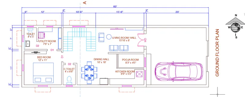
GROUND FLOOR PLAN
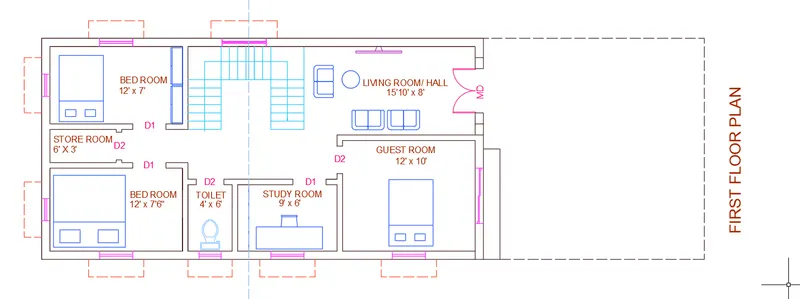
FIRST FLOOR PLAN
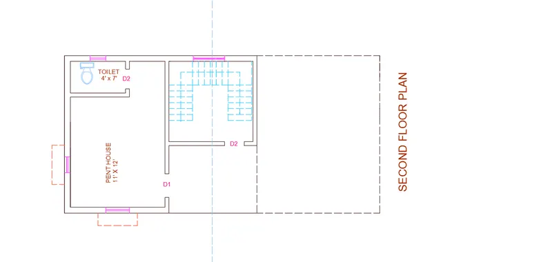
SECOND FLOOER PLAN
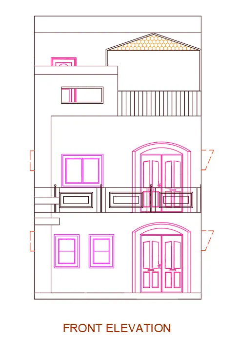
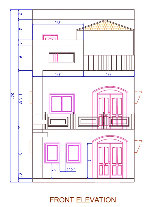
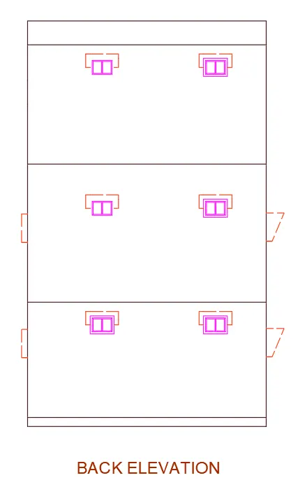
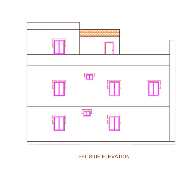
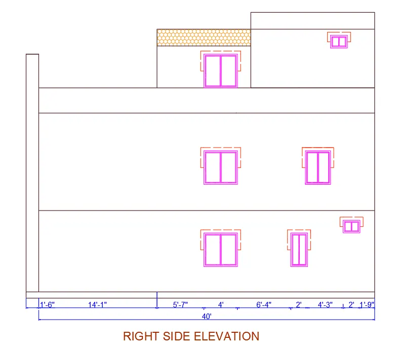
ELEVATIONS
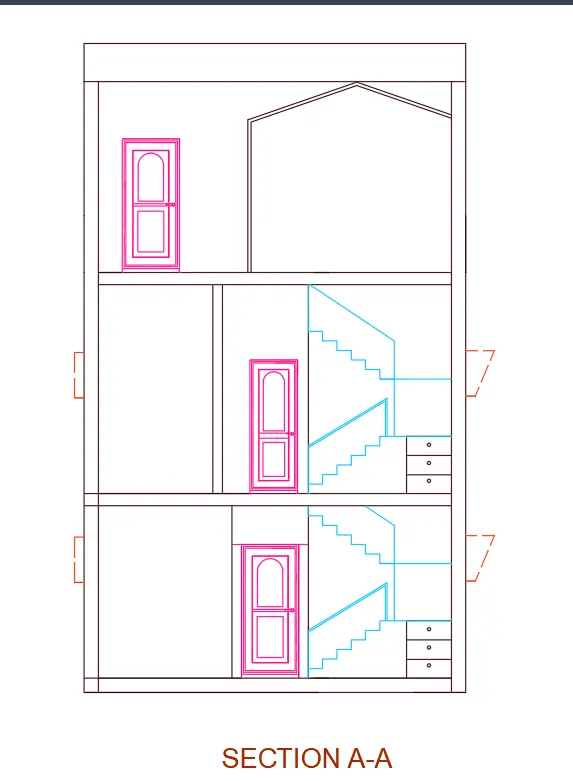
SECTION
2. Structural Drawing (Column, Beam, Footing Plan)
- Column Shape Choose :At first, choose the column shape. Different types of column shapes used in different structures; such as circular, rectangular, box-type columns. So, it is necessary to choose the column shape first.
- Draw the Column :After fixed the column shape the 2nd step to draw the column. Draw the column by using a rectangle (rec+Enter) or circle(c+Enter) command.
- Fixed the Column Location: The column position is the most important part of a structure. The beauty of a structure is depending on the position of the column. So, placed all column in the right position.
- Set the Grid Line: Gridline is a very important part of a structure because the position of all parts of the structure is set on the basis of the grid line. Draw the grid line (horizontal & vertical) by using line (l+Enter) or construction line (xl+Enter) command.
- Numbering the Grid Line: Numbering the grid line by a,b,c….. or 1,2,3….. Serially. It helps to locate something very easily.
- Set the Dimension Respect to Grid Line: Set a dimension of all column respect to the grid line by using dim leaner (diml+Enter) command. Because without dimension it’s impossible to locate a column position.
- Numbering the Column: Find a column to see the schedule is not possible without accurate numbering. So, Number the column to the basis of its size & reinforcement.
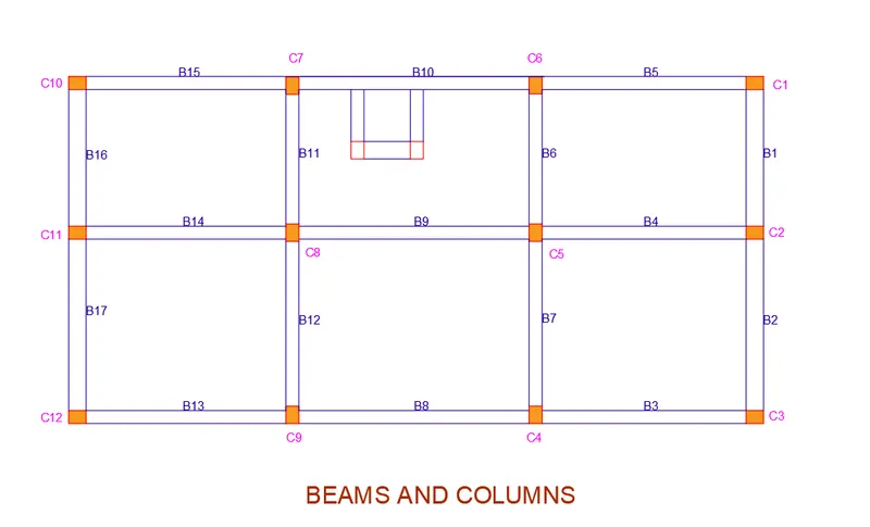
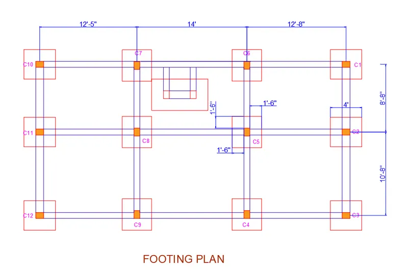
RESULT:
- Residential building of dimensions 60' x 20’ with the following drawing Architectural drawing plot drawing ground floor plan first floor plan elevation view Structural drawing section view footing layout column layout beam layout is successfully drawn by using AutoCAD software.