Drafting of various geometries using Chamfer, Fillet tool in AutoCad
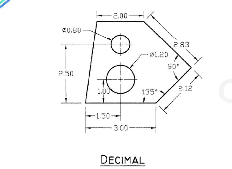
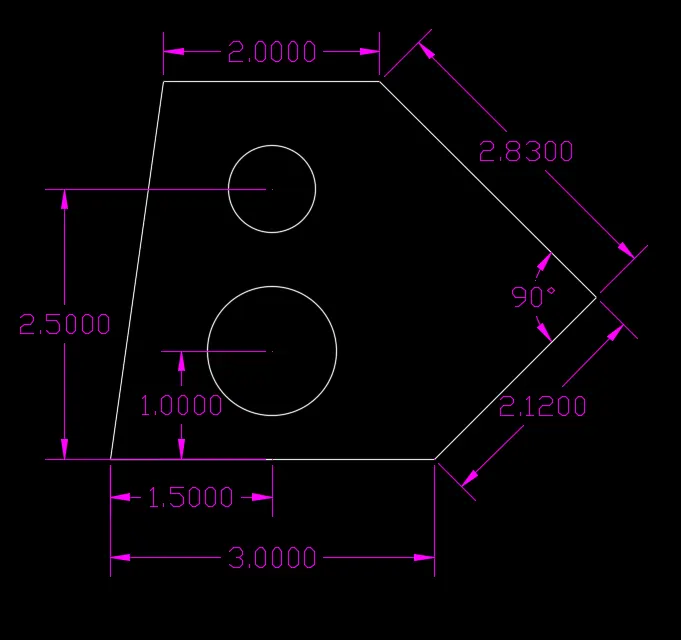
1.Draft the figure by using Autocad in the Decimal units
AIM:
To draw the given drawing using AutoCAD software in decimal units
PROCEDUE:
1.In the command line type Units and select Decimal unit
2. In The command line type PL (Polyline) Then specify start point 1,1
- In the command line type @3<0
- In the command line type @2.12 <45
- In the command line type @2.83<135
- In the command line type @ 2<180
- In the command line click close
3. Now we have to draw the Circle
- In the command line type OBJECT SNAP
- In the object snap select END POINT, MIDPOINT then click on OK
- Select the midpoint of line with dimension 3
- In the command prompt type @1<90
- In the home tab draw pannel click on circle then select centre, diameter circle
- By using the cursor click on the endpoint of the previous line which is taken as centre of the circle
- In the command line type 1.20 (diameter) Then Delete 190 line
4. In the command prompt type OBJECT SNAP then in the object snap click on END POINT, MIDPOINT.
Select the midpoint of line with dimension 3
In the command line type @2.50<90
In the Home tab Draw pannel click on circle then select centre, diameter circle
By using the cursor click on the endpoint of the previous line which is taken as centre of the circle then select diameter give the dia as 8 units. Then delete the @2.50 <90 line
RESULT :
The given figure drawn by using AUTOCAD Software In the Decimal units
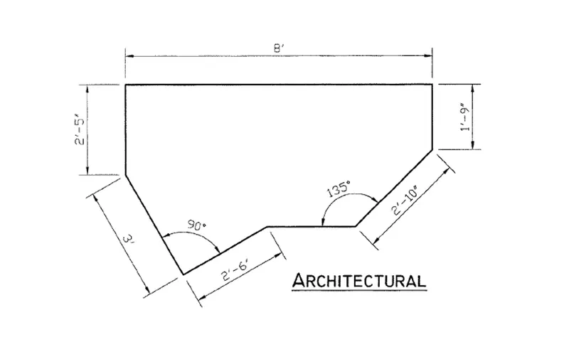
2.Draft the figure by using Autocad in the Architectural units
AIM:
To draw the given drawing using AutoCAD software in Architectural units
PROCEDUE:
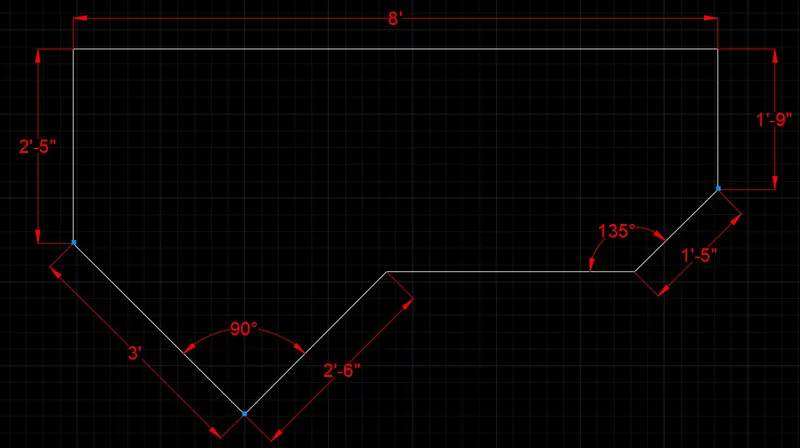
1.In the command line type Units and select Architectural units
2.Click on The polar tracking then seleck the 45,90,135,180
3.Now Give The command line or polyline then select a point then by using the cursor rotate round the angles are snaping then stop where the <135 located then give the length of line as 3'
4.Again in the direction of <90 give the dimention of 2'5" then move to the cursor in the <0 direction give the length 8' and Then <90 downward length 1'9" then <135 directon 1'5" then click on Esc
5.in The command line give the line command the select the first point of the line at where the starting point specifed then take the cursor in the <45 direction then give the length 2'6" then click the end point where we Esc it.
RESULT :
The given figure drawn by using AUTOCAD Software In the Architectural units
3.Draw the figure by using Autocad in the Architectural units
AIM:
To draw the given drawing using AutoCAD software in Engineering units
PROCEDUE:
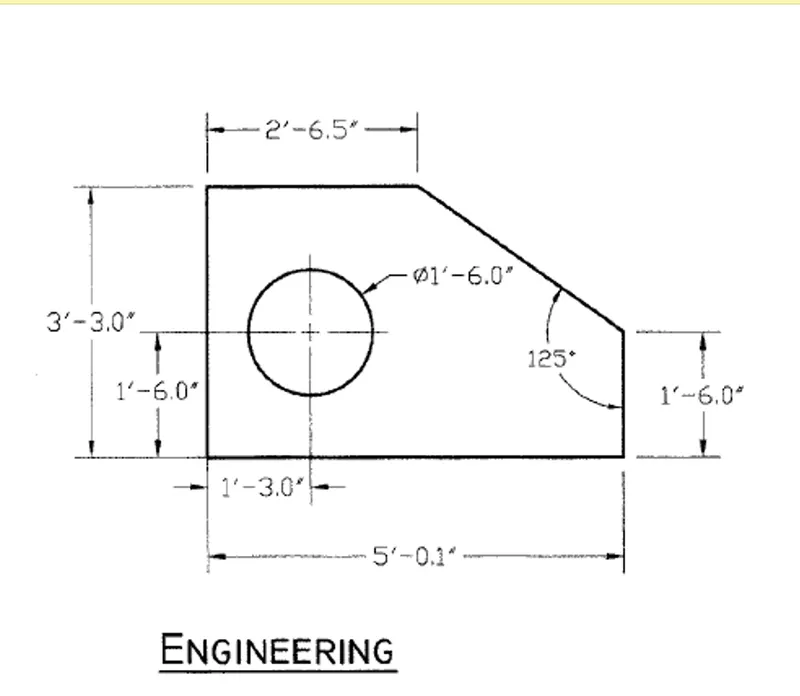
1.In the command line type Units and select Engineering units select precesion > 0'-0"
2.In the command line give the the line then specify the point then give the length 5'-0.1" Then give length 1'-6.0" in upward direction then press Esc
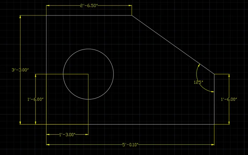
3.Give the command line Then specify the first point at starting point of 5'-0.1" line then upward direction give the length of line 3'-3.0" then In the <0 direction give the length of the line as 2'-6.5" Then join the previous line the its its internal angle created as <125
4.Give the command line then specify the line at starting point then <90 direction give the length of line 1'-6.0" then <0 Direction give the length of line 1'3.0" then click Esc
5.Now to create circle give the commad circle or then specify the centre point at end point of 1'3.0" then give the diameter 1' 6.0"
6.Delete the line we created in the 4th point
7.Give command DIM then mention the dimentions of give figure.
RESULT:
The given Figure Drawn By using AutoCAD software in Engineering units
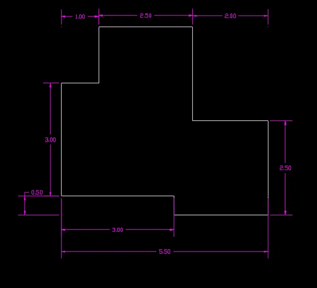
4.Draw the figure by using Autocad
AIM:
To draw the given drawing using AutoCAD software
PROCEDUE:
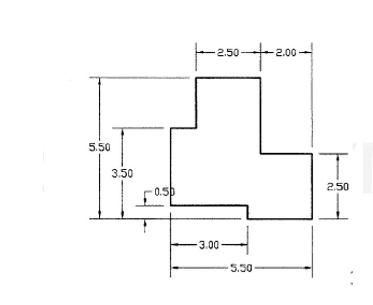
1.In the command line Type Units and select Decimal unit
2. In The command line type PL (Polyline) Then specify start point 1,1. Then In the command line type line Distance 3 then downward direction 0.5 than horizantal direction 2.5 then upward direction 2.5 then hotizantal direction (Negative x direction) 2 Units then upward direction 3 Then negative x direction 2.5 Then downward direction 2 then -ve x direction 0.5 then close the line where we started.
3.Give command DIM then mention the dimentions of give figure.
RESULT :
The figure is Drawn by using Autocad
5.Draw the figure by using Autocad
AIM:
To draw the given drawing using AutoCAD software
PROCEDUE:
1.In the command line Type Units and select Decimal unit
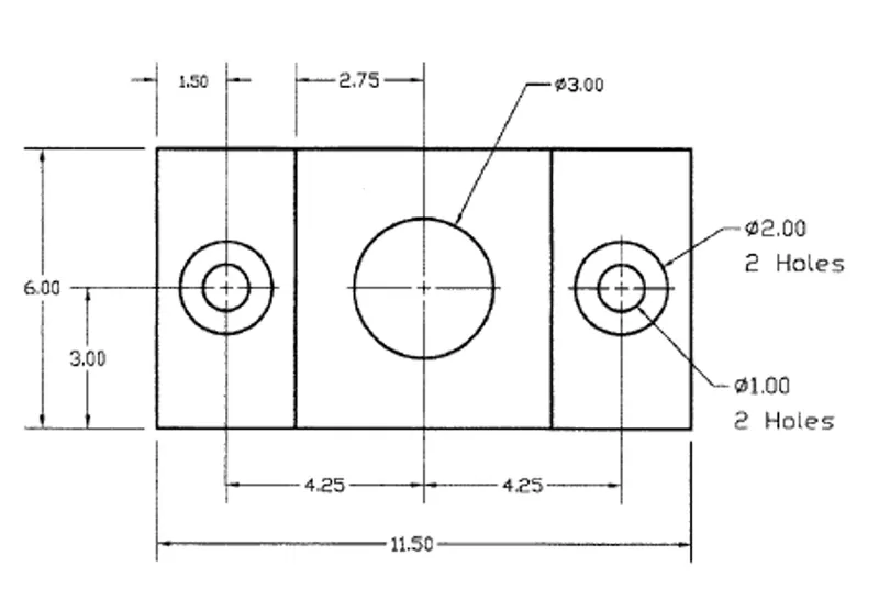
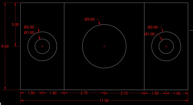
2. In The command line type PL (Polyline) Then specify start point 1,1.Then next point give the length of 11.50 Then Upword direction 6.00 Then -ve x direction 11.50 then close at starting point.
3.Give the command offest and select the left 6 unit line Then give the offset distance 1.50 Then Again same length click in right side direction amd Then give the offset distance 2.75 then click Right side and Then select offest line then again click right side Then press Esc
4.Give the command Offset select the 11.5unit line then offset at a distance of 3.00units inner side of the fig.
5. To create the circle give the command then click at first 3.0unit line and the 1.5unit line intersection point then give the dia 1unit the again circle command select the same point and give the dia 2units.
6.Copy the both circle then paste at right side of intersection point.
7.Give The command circle Then select the centre point at horizantal4.25unit line and 3.00unit vertical line intersection point then give the dia 3units.
8.Delete the unwanted lines.
8.Give command DIM then mention the dimentions of give figure.
RESULT:
The figure is Drawn by using Autocad
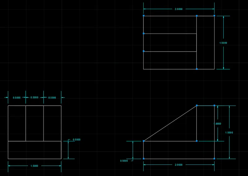
6.Draw the figure by using Autocad
AIM:
To draw the given drawing using AutoCAD software
PROCEDUE:
1.In the command line Type Units and select Decimal unit
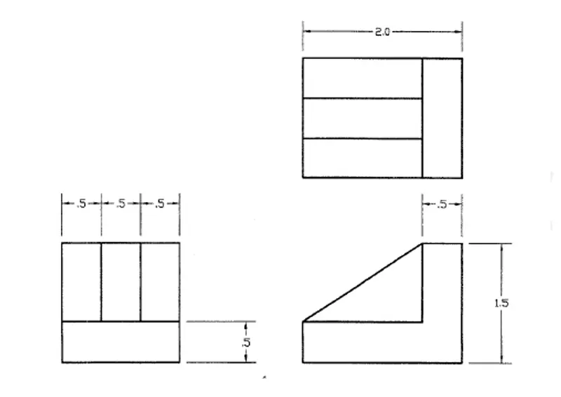
2. In The command line type PL (Polyline) Then specify start point 1,1
- In the command line type line.
- In the command line type distance 1.5
- In the command line type distance 1.5
- In the command line type distance 1.5
- In the command line type distance 1.5
- In the command line type offset
- In the command prompt type offset distance 0.5
- With the help of offset get a horizontal line of distance 0.5 With the help of offset get two vertical line of each distance 0.5
- In the command line type line
- In the command line distance 2.0
- In the command line type distance 1.5
- In the command line type distance 2.0
- In the command line type distance 1.5
- In the command line type offset
- In the command line type offset distance 0.5
- With the help of offset get a vertical line of distance 0.5
- With the help of offset get two horizontal line of each distance 0.5
- Extended the horizontal lines from the right rectagular drawing
- Extended the vertical lines from the top rectangular drawing With the help of line command join the intersecton points And trim the extras with the help of trim command
AIM:
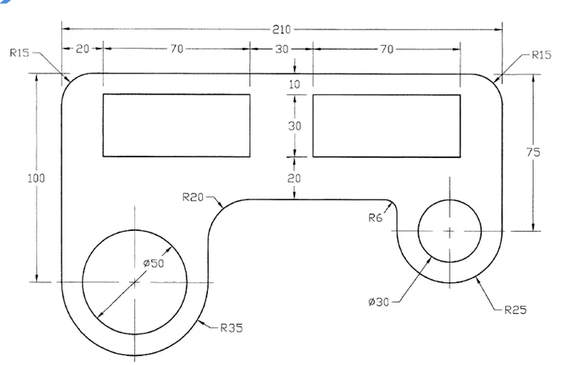
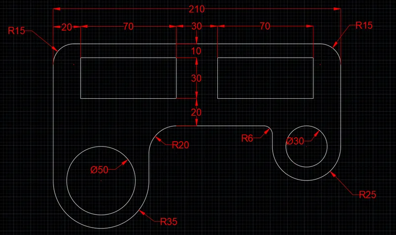
To draw the given figure in the autocad in detail.
PROCEDURE :
Step-1
- First open autocad and set the units to decimal and set presicion to 0.0000 with the unit command and dimstyle command.
- First draw the line using the line command towards the length of 210.0000 units in the top.
- Next draw the line downwards with the Irngth of 75.0000 units from the previous point.
- Next draw the line towards back with length of 50.0000 units from the previous point.
- Then next draw the upwards from the last line with the length of 15.0000 units.
- Next draw the line towards back with the length of 90.0000 units.
- Next draw the line downwards with the length of 40.0000 units from the previous point.
- Next draw the line backwards with the length of 70.0000 units from the last point of previous one.
- Then join the 1st line and last line then the figure will be closed.
Step-2
- After joining al the lines, we have to create the rectangles inside the figure.
- The rectangle is created at a distance of 10.0000 units at the top.
- The second rectangle is placed with a distance of 30.0000 units from the first rectangle.
Step-3
- Next use the fillet commant to create the arch between two lines.
- Enter the fillet command in command box and select radius, then select the two lines to form arc with radius 25.0000 units at right side of the figure
- Then use the circle command and draw with the diameter of 30.0000 units.
Step-4
- Next use the fillet commant to create the arch between two lines.
- Enter the fillet command in command box and select radius, then select the two lines to form are with radius 35.0000 units at left side of the figure
- Then use the circle command and draw with the diameter of 50.0000 units, at the left side of the figure
- Next put the dimentions for every part in the drawing.
RESULT:
The given figures are drawn successfully in autocad
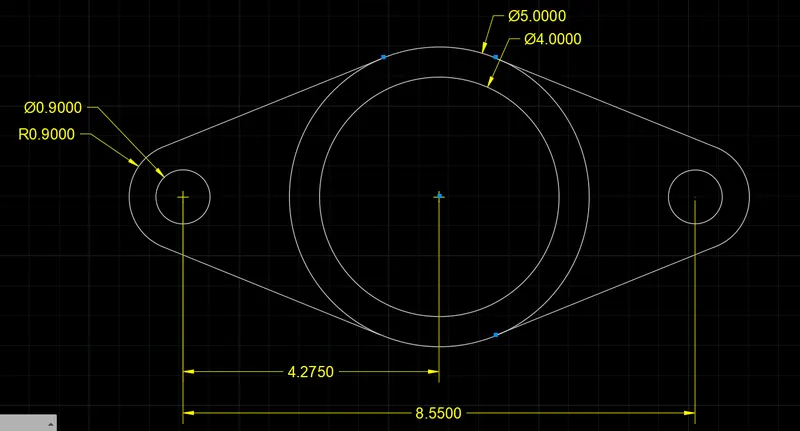
8.Draw the given figure in the autocad in detail.
AIM:
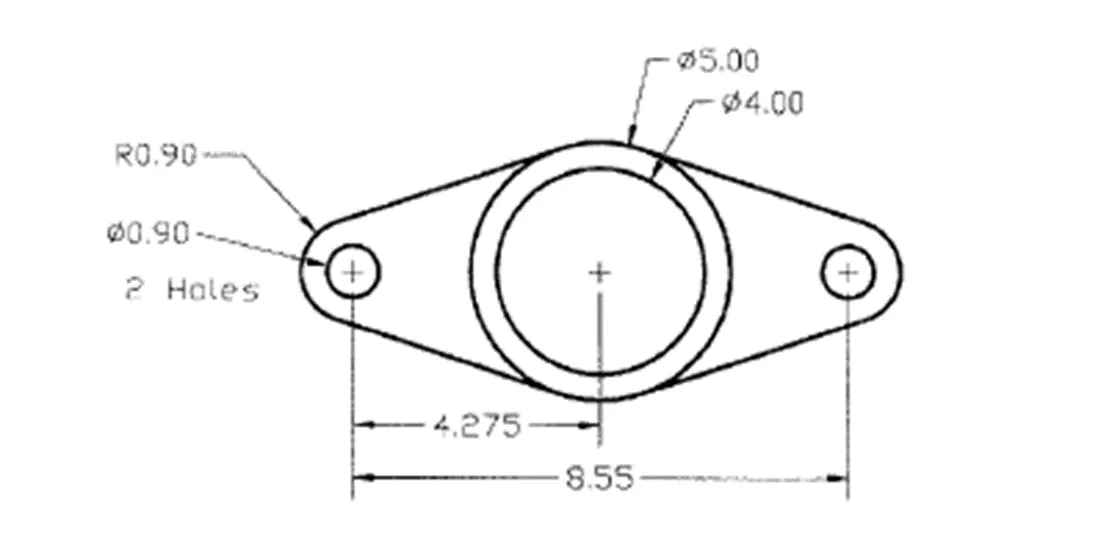
To draw the given figure in the autocad in detail.
Procedure:
Step:1
- First open autocad and set the units to decimal and set presicion to 0.0000 with the unit command and dimstyle command.
- First draw the line using the line command with the length of 8.5500 units.
- Next from left side draw the line vertically with the length of 1.8000 units at the centre to the horizontal line.
- Similarly from the right side draw the line vertically with the length of 1.8000 units at the centre to the horizontal line.
Step:2
- Next draw the circle at centre of the horizontal line with the diameter of 4.0000 units.
- Again draw the circle at centre of horizontal line with the diameter of 5.0000 units.
Step:3
- Now draw a line from end points to the top of the circle.
- This is Similar to the all ends to draw a line to the top of the circle.
Step:4
- Now draw the circles at left and right sides of the both ends to the centre of horizontal line.
- Draw the circles of diameter 0.9000 units both left end and right end.
Step:5
- Now use the fillet command to join the two lines with arc.
- Then select the fillet command in command box and select lines to form the arc between two lines.
- Then the radius of arc is 0.9000 units, atthe both ends.
Step:6
- Finally use the trim command to remove unwanted lines.And then we drawn the given figure.
- Next put the dimentions for every part in the drawing.
Result:
The given figure is drawn successfully in autocad.
9.Draw the given figure in the autocad in detail.
Aim:
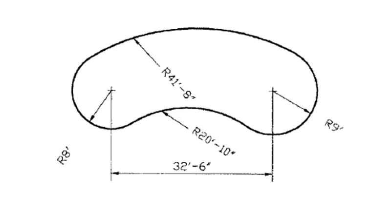
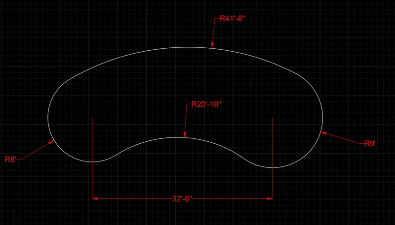
To draw the given figure in the autocad in detail.
Procedure:
Step:1
- First open autocad and set the units to architectural and set presicion to 0'.0" with the unit command and dimstyle command.
- First draw a line using the line command with the length of 32'-6".
- Then draw a circles for both left end and right end of the line.
- The Radius of left side circle is 8' and the radius of right side circle is 9'.
Step:2
- Next use the arch (start,end,radius) from top of the first circle to the top of the second circle.
- After entering the arc at top with the radius of 41-8"
Step:3
- Again we have to use the arc(start,end,radius) command to create the arc between the first circle and the second circle.
- After entering the arc command at bottom with the radius of 20'-10".
Step:4
- Now we use the trim command to trim the unwanted things in the drawing.
- Next put the dimentions for every part in the drawing.
Result:
The given figure is drawn successfully in Autocad.
10.Draw the given figure in the autocad in detail.
Aim:
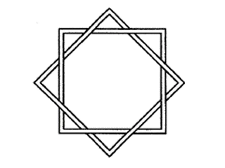
To draw the given figure in the autocad in detail.
Procedure:
Step:-1
- First we have to enter the rectangle command in the command box, and select the dimensions option after entering the rectangle command.
- Then after selecting the dimensions, then give the dimensions, the length is 3.0000 units and width is 3.0000 units.
- The dimensions are not given, but i assumed the dimensions.
Step:2
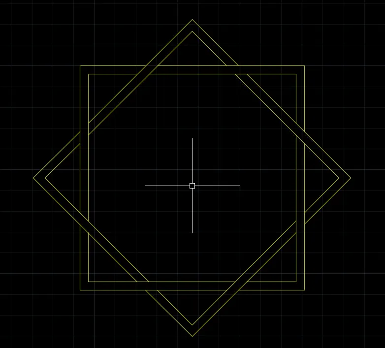
- Then we use the offset command to offset the rectangle.
- Take any value as offset value, then do the offset.
Step:-3
- Here we use the rotate command to rotate it.
- Then we rotate it to the inclined angle(45 degrees) using the rotate command.
Step:-4
- The rotated offsetted rectangle has been placed on the non-rotated rectangle.
- And trim the unwanted lines in the drawing.
Result:
The given figure is drawn successfully in autocad.
11.Draw the given figure in the autocad in detail.
Aim:
To draw the given figure in the autocad in detail.
Procedure:
Step:1
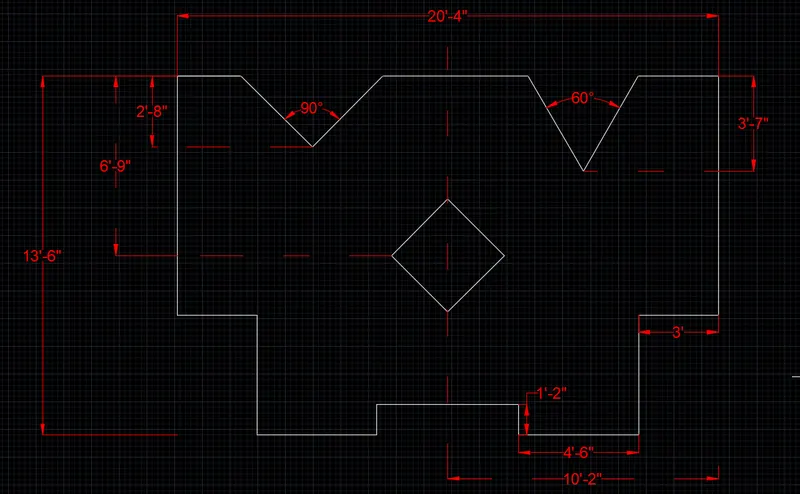
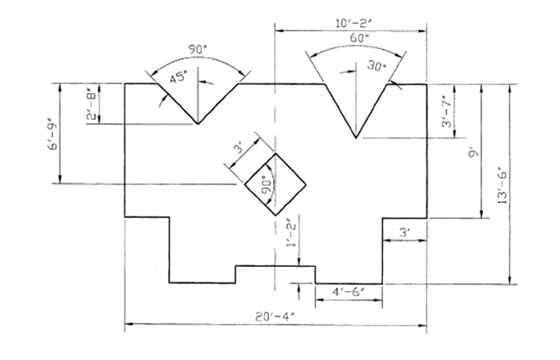
- Now we draw the line using line command with the length of 1-2" downwards.
- Next draw line forward with the length of 4'-6" from the previous line.
- Next draw the line upwards with the length of 4'-6" from the previous line.
- Now we draw the line using line command with the length of 3' forward.
- Draw line upwards with the length of 9' from the previous line.
- Next draw the line towards back with the length of 20'-4" from the previous line.
- Now we draw the line using line command with the length of 6'-9" downward direction
Step:2
- First we draw the rectangle separately with the dimensions of length 3' and width 3'.
- Now locate the center of the object and place the rectangle at the centre of the object.
- Next we rotate the rectangle to the 45 degrees.
Step:-3
- Now we place the angles at the top of the object, then we place the angle 45 degrees and 90 degrees at a distance of 5'-1" from the left side of the object at the top.
- And another angles 30 degrees and 60 degrees were placed at a distance of 5-1" from the right side of the object at the top.
- Next put the dimentions for every part in the drawing.
Result:
The given figure is drawn successfully in Autocad.