Creating a Floor plan, Footing detail and Isometric view using AutoCad
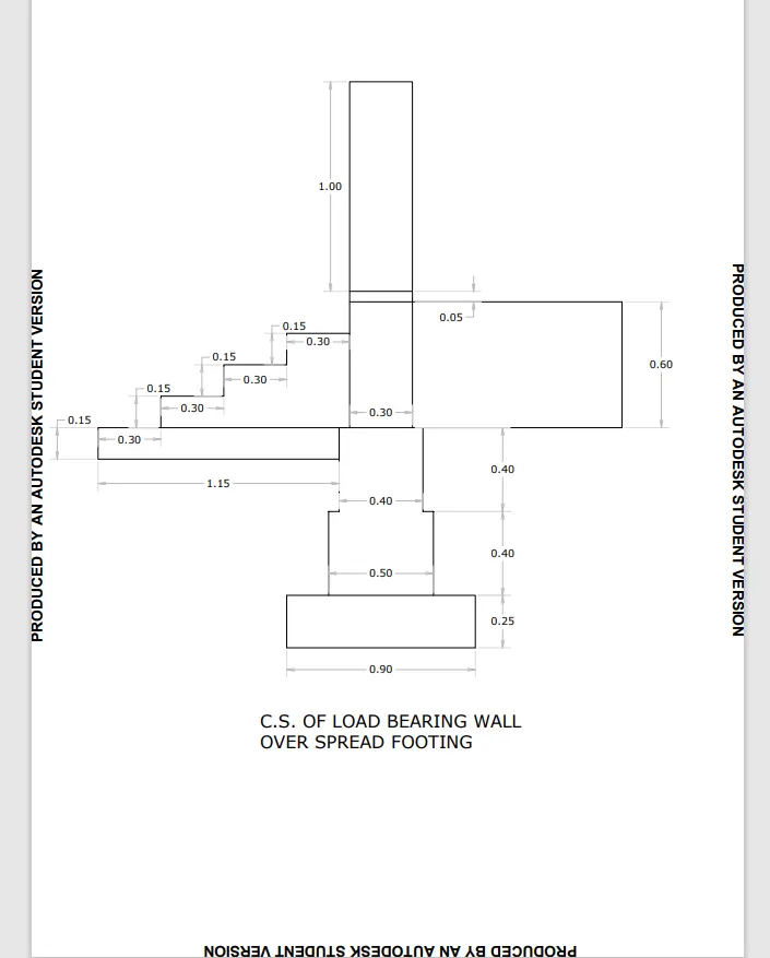
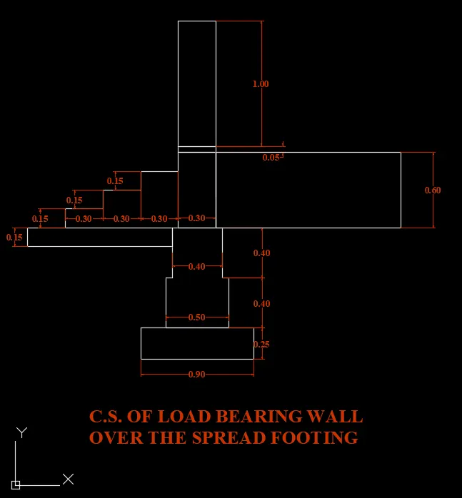
1.C1 Draw the C.S. LOAD BEARING WALL OVWER SPREAD FOOTING By using AUTO CADD Software.
AIM :
To draw the C.S. LOAD BEARING WALL OVWER SPREAD FOOTING By using AUTO CADD Software.
PROCEDURE :
1.Open the Auto cad software.
2.The user inter face opened then go to the application menu Select the New Template file
3.Then select Start from scratch in that select the IMPERIAL Templet
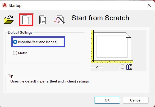
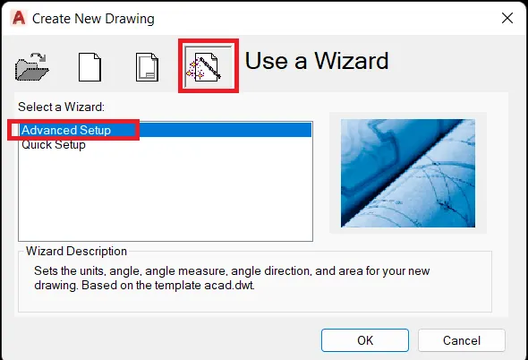
4.Next select USE A WIZARD Then select Advanced Set up
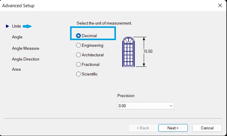
5.Next Select DECIMAL and Precision for this drawing =0.00
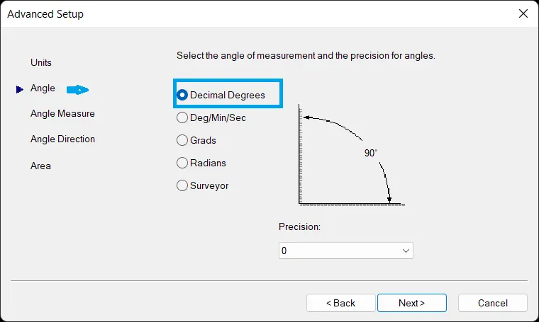
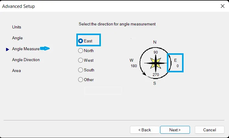
6.Next Angle as DECIMAL DEGREE and put the and mesure as EAST = O
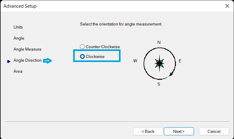
7.Then Angle Direction as CLOCK WISE then area as length 9.0 and width 12.0 then click on Finish.
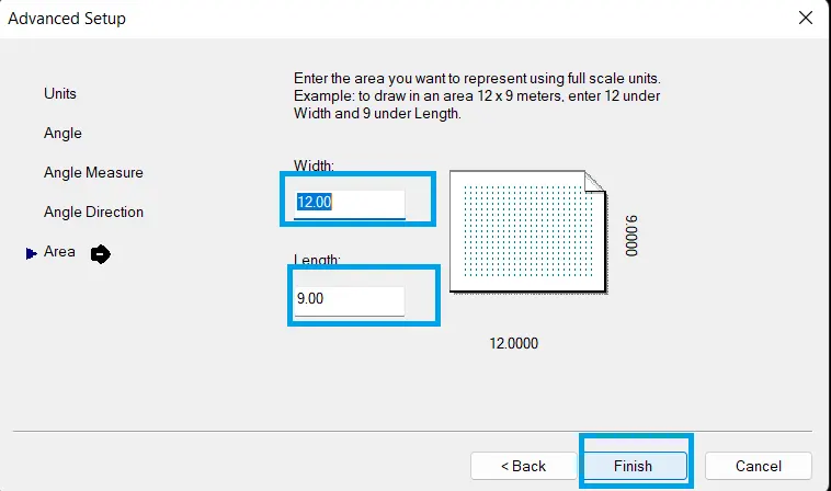
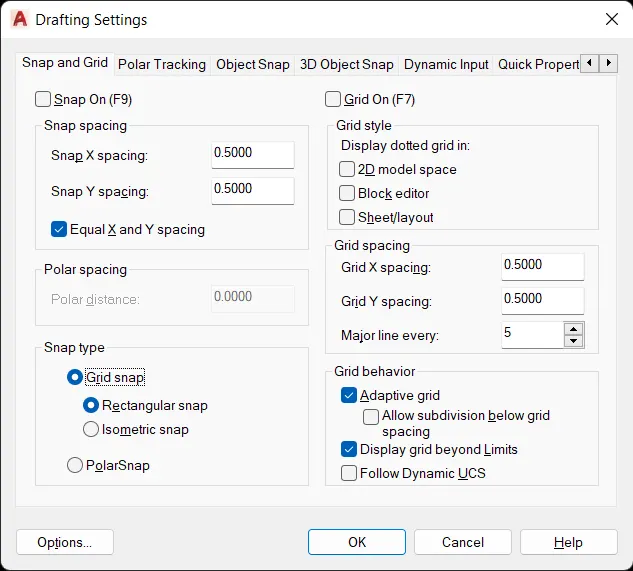
8. In the commond prompt type DS then the Drafting Setting will opend then put as The Snap spacing as 0.5 and the Grid spacing as 0.5 in both x,y direction and then click on OK.
9.Now start drafting give the command Rec in the Command line window then give The First corner poin = (1,1) click on enter then the rectangle pointed then select the dimention in command prompt then give dimentions as length 0.9 the width 0.25 then enter. The rectangle will created.
10.Again give the command REC in the Command line window then specify the first corner point (1.2 , 1.25) Then click on dimentions and give the length =0.5 , width = 0.4 Then another rectangle will created in the specifed place.
11.Again give the command REC then specify the first corner point (1.25 , 1.65) Then click on dimentions and give the length =0.4 , width = 0.4 Then another square will created.
12.Give the command REC then specify the first corner point (1.30 , 2.05) Then click on dimentions and give the length =0.3 , width = 0.6 Then The rectangle will created.
13.Give the command REC in the Command line window Then specify the first corner point (1.30 , 2.65) Then click on dimentions and give the length =0.3 , width = 0.05 Then The rectangle will created.
14.Give the command REC in the Command line window Then specify the first corner point (1.30 , 2.7) Then click on dimentions and give the length =0.3 , width = 1.0 Then The rectangle will created.
15.Give the command REC in the Command line window Then specify the first corner point (1.25 , 2.05) Then click on dimentions and give the length =1.15 , width = 0.15 Then The rectangle will create left side.
16.Give the command Line in the Command line window Then specify the first corner point (0.4 , 2.05)
- Then specify the next point as @0.15<90
- Then specify the next point as @0.3<0
- Then specify the next point as @0.15<90
- Then specify the next point as @0.3<0
- Then specify the next point as @0.15<90
- Then specify the next point as @0.3<0
17.Give the command DIMLINEAR in the Command line window Then give Them Dimentions at every corner node points. (I have changed the layer properties colour to colour 22 to separate the Drawing and the dimentions ).
18.Then Give the command as MT Then The Multiline Text will create give the hight and then specify the corner point and create text CC OF LOAD BEARING WALL
OVER THE SPREAD FOOTING. Then save the file by Ctrl+S or give command as QSAVE and give the file name and Select The Location of the file and Select The Files of type
RESULT :
The C.S. LOAD BEARING WALL OVWER SPREAD FOOTING is created by Using AUTO CAD Software
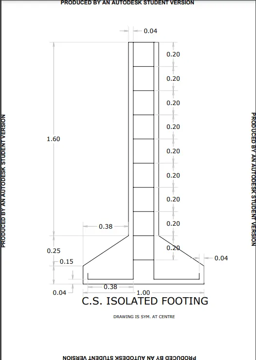
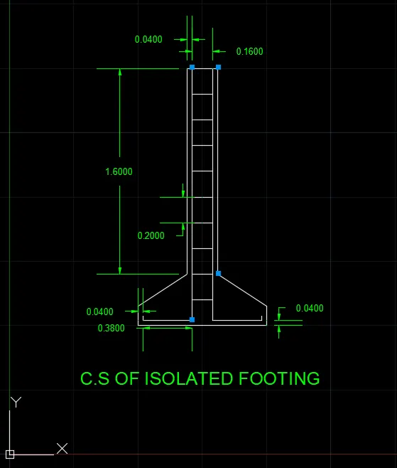
2.C2:Draw the C.S. ISOLATED FOOTING By using AUTO CADD Software.
AIM:
TO Draw the C.S. ISOLATED FOOTING By using AUTO CADD Software
PROCEDURE :
1.Open the Auto cad software.
2.The user inter face opened then go to the application menu Select the New Template file
3.Then select Start from scratch in that select the IMPERIAL Templet
4.Next select USE A WIZARD Then select Advanced Set up
5.Next Select DECIMAL and Precision for this drawing =0.00
6.Next Angle as DECIMAL DEGREE and put the and mesure as EAST = O
7.Then Angle Direction as CLOCK WISE then area as length 9.0 and width 12.0 then click on Finish.
8. In the commond prompt type DS then the Drafting Setting will opend then put as The Snap spacing as 0.5 and the Grid spacing as 0.5 in both x,y direction and then click on OK.
9.Now start drafting give the command LINE in the Command line window then give The First corner poin = (1,1) click on enter then the Next point @ 1<0 Then nxt point @ 0.15 < 90 then Esc
10.Line command then The First point (1.04,1.04)
- Then next point @0.38<0
- Then next point @1.96<90
- Then next point @0.17<0
- Then next point @1.96<270
- Then next point @0.38<0
- Then next point @0.05<90 Then esc
11.Line command then The First point (1.04,1.04) Then Next point @0.05<90
12.Line command then The First point (1.42,3.00) Then Next point @0.04<180, Then Next point @1.60<270
13.Join the coordinate points (1.38,1.40) (1,1.15) by using line command.
14.Line command then The First point (1.59,3.00) Then Next point @0.04<0, Then Next point @1.60<270
15.Join the coordinate points (1.63,1.40) (2,1.15) by using line command.
16.Select the line of b/w coordinates (1.42,3.00),(1.59,3.00) Then give command OFFSET enter then give the distance 0.2 then pressing enter we will get muliple lines at intervel of 0.2
17.We have to offset the line until the required in the design.
18.Give the command DIMLINEAR in the Command line window Then give Them Dimentions at every corner node points.
19.Then Give the command as MT Then The Multiline Text will create give the hight and then specify the corner point and create text CC ISOLATED FOOTING.
20.Then save the file by Ctrl+S or give command as QSAVE and give the file name and Select The Location of the file and Select The Files of type.
RESULT :
The C.S. ISOLATED FOOTING Created By using AUTO CADD Software.
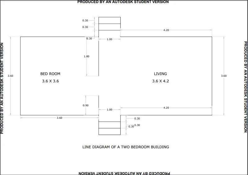
3. C3 Draw The Line Diagram of a Two Roomed Building
AIM :
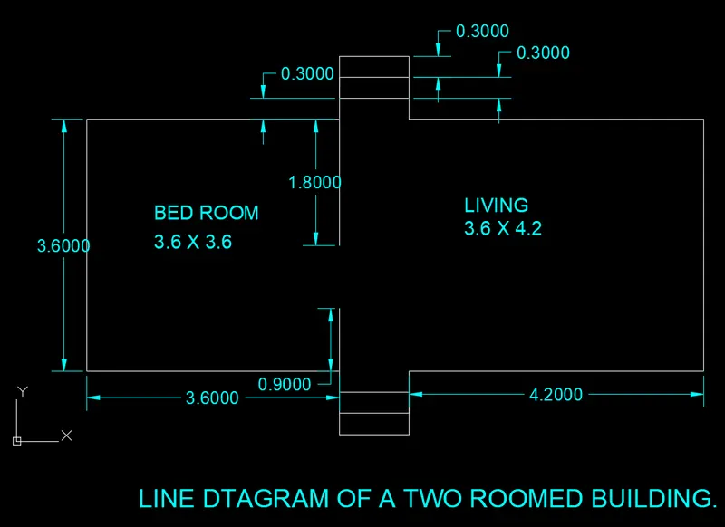
To Draw The Line Diagram of a Two Roomed Building by Using AUTOCAD Saftware.
PROCEDURE :
1.Open the Auto cad software.
2.The user inter face opened then go to the application menu Select the New Template file
3.Then select Start from scratch in that select the IMPERIAL Templet
4.Next select USE A WIZARD Then select Advanced Set up
5.Next Select DECIMAL and Precision for this drawing =0.00
6.Next Angle as DECIMAL DEGREE and put the and mesure as EAST = O
7.Then Angle Direction as CLOCK WISE then area as length 9.0 and width 12.0 then click on Finish.
8. In the commond prompt type DS then the Drafting Setting will opend then put as The Snap spacing as 0.5 and the Grid spacing as 0.5 in both x,y direction and then click on OK.
9.Now start drafting give the command LINE in the Command line window then give The First corner poin = (1,1)
- Then the next point @3.60<0
- Then the next point @0.9<270
- Then the next point @1.0<0
- Then the next point @0.9<90
- Then the next point @4.20<0
- Then the next point @3.60<90
- Then the next point @4.20<180
- Then the next point @0.9<90
- Then the next point @1<180
- Then the next point @0.9<270
- Then the next point @3.60<180 Then click on close
10.Give the command LINE in the Command line window then give The First corner poin = (4.60,4.60) Then next point @1.80<270
11.Then Give the command OFFSET in the Command line window Tehn specify the offset distance 0.30. Click on the line in which coordinate points are (4.60,0.10) and (5.60,0.10) Then click on the previous line to get segments
12.Click on the line in which coordinate points are (4.60,5.50) and (5.60,5.50) Then click on the previous line to get segments.
13.Give the command DIMLINEAR in the Command line window Then give Them Dimentions at every corner node points.
14.Then Give the command as MT Then The Multiline Text will create give the hight and then specify the corner point and create text The LINE DTAGRAM OF A TWO ROOMED BUILDING.
15.Then save the file by Ctrl+S or give command as QSAVE and give the file name and Select The Location of the file and Select The Files of type.
RESULT :
The Line Diagram of a Two Roomed Building Created by Using AUTOCAD Saftware
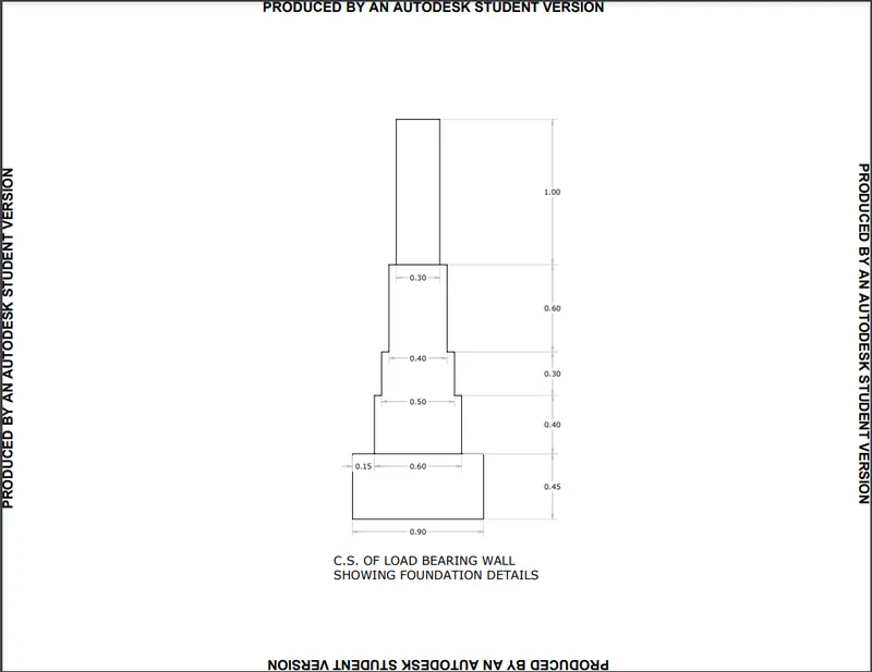
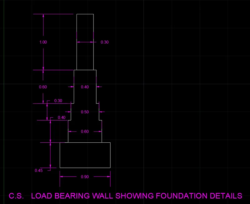
4. C4 Draw the C.S. LOAD BEARING WALL SHOWING FOUNDATION DETAILS.
AIM:
To Draw the C.S. LOAD BEARING WALL SHOWING FOUNDATION DETAILS.
PROCEDURE :
1.Open the Auto cad software.
2.The user inter face opened then go to the application menu Select the New Template file
3.Then select Start from scratch in that select the IMPERIAL Templet
4.Next select USE A WIZARD Then select Advanced Set up
5.Next Select DECIMAL and Precision for this drawing =0.00
6.Next Angle as DECIMAL DEGREE and put the and mesure as EAST = O
7.Then Angle Direction as CLOCK WISE then area as length 9.0 and width 12.0 then click on Finish.
8. In the commond prompt type DS then the Drafting Setting will opend then put as The Snap spacing as 0.5 and the Grid spacing as 0.5 in both x,y direction and then click on OK.
9.Now start drafting give the command Rec in the Command line window then give The First corner poin = (1,1) click on enter then the rectangle pointed then select the dimention in command prompt then give dimentions as length 0.9 the width 0.45 then enter. The rectangle will created.
10.Again give the command REC in the Command line window then specify the first corner point (1.15 , 1.45) Then click on dimentions and give the length =0.6 , width = 0.4 Then another rectangle will created
11.Again give the command REC in the Command line window then specify the first corner point (1.20 , 1.85) Then click on dimentions and give the length =0.5 , width = 0.3 Then another rectangle will created
12. Give the command REC in the Command line window then specify the first corner point (1.25 , 2.15) Then click on dimentions and give the length =0.4 , width = 0.6 Then another rectangle will created
13. Give the command REC in the Command line window then specify the first corner point (1.3 , 2.75) Then click on dimentions and give the length =0.3 , width = 1.0 Then another rectangle will created
14.Give the command DIMLINEAR in the Command line window Then give Them Dimentions at every corner node points.
15.Then Give the command as MT Then The Multiline Text will create give the hight and then specify the corner point and create text C.S. LOAD BEARING WALL SHOWING FOUNDATION DETAILS.
16.Then save the file by Pressing Ctrl+S or give command as QSAVE and give the file name and Select The Location of the file and Select The Files of type.
RESULT :
The C.S. LOAD BEARING WALL SHOWING FOUNDATION DETAILS is created by Using AUTO CAD Software
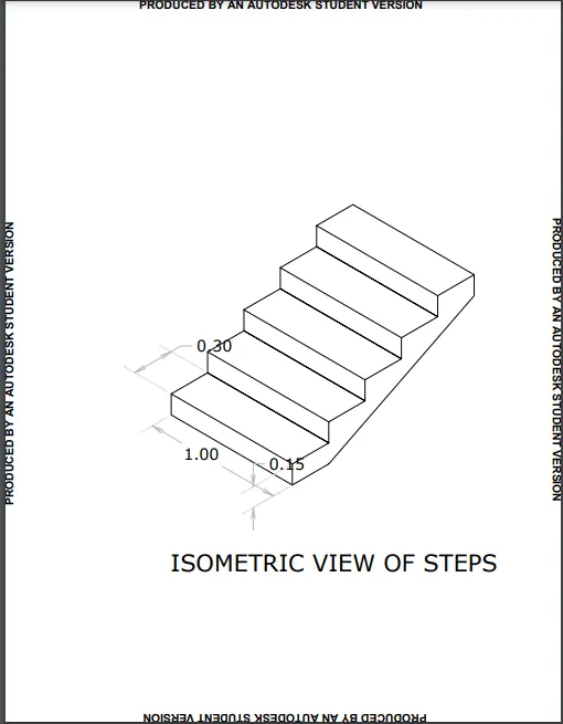
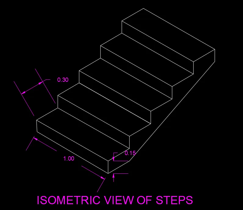
5.C5 Draw the ISOMETRIC VIEW OF STEPS Using AUTO CAD Software
AIM:
To Draw the ISOMETRIC VIEW OF STEPS
PROCEDURE :
1.Open the Auto cad software.
2.The user inter face opened then go to the application menu Select the New Template file
3.Then select Start from scratch in that select the IMPERIAL Templet
4.Next select USE A WIZARD Then select Advanced Set up
5.Next Select DECIMAL and Precision for this drawing =0.00
6.Next Angle as DECIMAL DEGREE and put the and mesure as EAST = O
7.Then Angle Direction as CLOCK WISE then area as length 9.0 and width 12.0 then click on Finish.
8. In the commond prompt type DS then the Drafting Setting will opend then turn of The Snap spacing and turn of the Grid spacing and then click on OK.
9.select ON the isometric snap
10. Keep Ortho on then give the command line
11.select the first point and give angle <150 then give distance 1
12.press on F5 (isodraft) for to get the line in desire direction
13.Give the line command <90 then 0.15 distance then <30 then distance 0.3
14. Repeat the above step for the 5 times because of 5 steps there in figure
15. select the 1unit line then copy it by clicking CO then copy the line at every edge of the step
16. select the 0.3unit line copy it and pick the edge point then paste at every edge
17.Aslo copy the 0.15 unit line copy it and pick the edge point then paste at every required edge.
18.Give the dimensions by using DIMLI command.
19.Then Give the command as MT Then The Multiline Text will create give the hight and then specify the corner point and create text ISOMETRIC VIEW OF STEPS.
20.Then save the file by Pressing Ctrl+S or give command as QSAVE and give the file name and Select The Location of the file and Select The Files of type.
RESULT :
The ISOMETRIC VIEW OF STEPS Drawn by Using theAUTO CAD Software
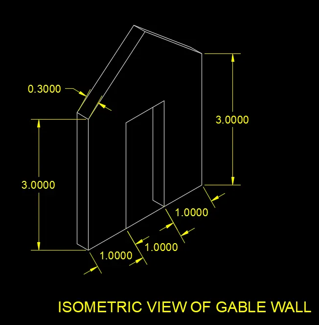
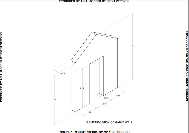
6.C6 draw THE ISOMERIC VIEW OF THE GABLE WALL by Using theAUTO CAD Software
AIM :
To Draw THE ISOMERIC VIEW OF THE GABLE WALL by Using theAUTO CAD Software
PROCEDURE :
1.Open the Auto cad software.marcl
2.The user inter face opened then go to the application menu Select the New Template file
3.Then select Start from scratch in that select the IMPERIAL Templet
4.Next select USE A WIZARD Then select Advanced Set up
5.Next Select DECIMAL and Precision for this drawing =0.00
6.Next Angle as DECIMAL DEGREE and put the and mesure as EAST = O
7.Then Angle Direction as CLOCK WISE then area as length 9.0 and width 12.0 then click on Finish.
8. In the commond prompt type DS then the Drafting Setting will opend then turn of The Snap spacing and turn of the Grid spacing and then click on OK.
9.select ON the isometric snap
10. Keep Ortho on then give the command line
11.Give the command line then specify the line then next point @<30, 1unit disatance Then @<90 ,2.42 Then @<30,1 Then <90,-2.42 Then @<30,1 Then @<90,3 Then then click on esc
12.Line command specify the where the first point then <90 Distance 3 units
13.Line command specify the where the first point then <150 distance 0.3 units
14.Mark The 3.25 from the base middle point then join the points by using line
15.Also joint the 0.3 unit lines in desire direction.
16.Give the dimensions by using DIMLI command.
17.Then Give the command as MT Then The Multiline Text will create give the hight and then specify the corner point and create text THE ISOMERIC VIEW OF THE GABLE WALL
18.Then save the file by Pressing Ctrl+S or give command as QSAVE and give the file name and Select The Location of the file and Select The Files of type.
RESULT :
THE ISOMERIC VIEW OF THE GABLE WALL Drawn by Using the AUTO CAD Software