Project 1 _Creating an Architectural plan for the provided plot size and develop relevant basic structural drawings
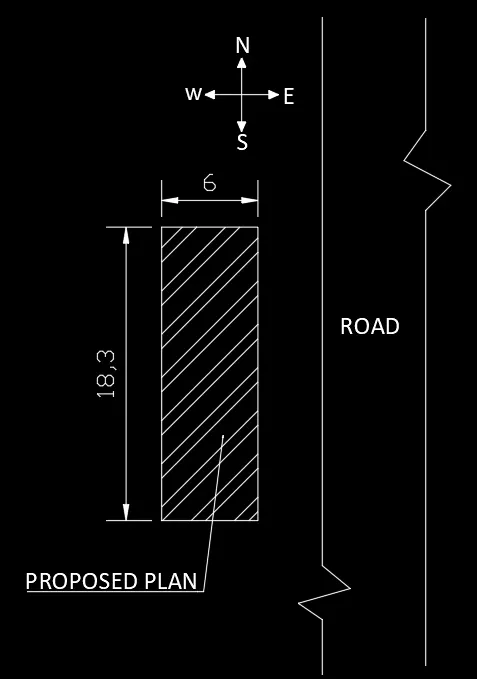
AIM:- To design and draft a layout of a residential building along with floor plan, elevation, section, column & beam & footing plan. The plot size is 60' X 20' (18.3m X 6m), house is facing east direction. Also, Use proper dimension techniques and dimension styles to document the project. I have assumed the sizes of the doors,windows, footings, columns, beams, slabs etc. as per construction standards.
INTRODUCTION:-
To draw the Plan and Sections according to the provided Figures, I have used several autocad commands like- line,circle, rectangle, extend , offset, trim,erase,hatch, leader, etc., and I set dimension (Decimal) and select milimeter in Autocad. Moreover, I set limits with command "Limits", specify the left corner points ans right corner points and then enter zoom all("z-a") in this drawing. Also, I used dimesion command for measuing the dimensions in Autocad along with text command to write drawing name. Apart from that, I have assumed several data for drawing this sketch.
Commands used:-
a. Line - Command "L" . Give the distance.
b. Offset - Command "O". Give the distance and select the line from where offset is to be done.
c. Rectangle -Command "REC". Click on dimnesion, enter the length and width .
d. Trim - Command "TR". Click on the line from where to be trimmed and then click on the line to be trimmed.
e. Extend -Command "EX" . Click on the line to which it has to be extended,then click on the line to be extended.
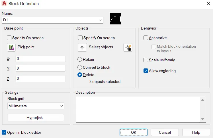
f. Block - Command "B" . Give name for the block , pick a point of the object, then select the object.
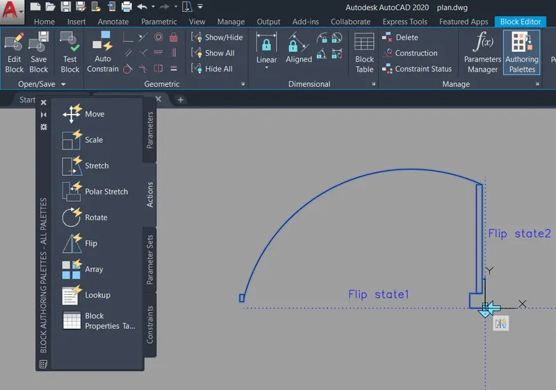
g. Blockedit -Command "BEDIT" . It is used to give parameters and actions to the block . For eg: to flip a door.
h. Dimension - Command "DIMLINEAR". select the points where dimension is to be marked . "DIMCONTINUE" is used to give dimensions continously,without selecting the base point each time.
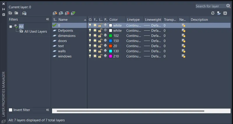
i. Layer - Command "LAYER". It is used to assign different properties to different elements in a drawing so that it is easy to work on each element .
j. Hatch - Command "H". Used to define the material property . Select the pattern and pick the object where hatch has to be displayed.
k. Design centre- From the insert toolbar. Use to insert the furnitures etc in drawing ,they are predefined blocks
l. Plot- To save drawing as pdf or other image format.
m. Layout - Layout is created in layout tab . To set the drawing before printing
PROCEDURE:-
Open Autocad and type a command "Unit" and press enter, then set unit as Decimal and set angle in degree- base angle is east -mark angle direction as anticlockwise. Type a command "DIMSTYLE" and press enter, then click to modify and go to primary unit tab and set it Decimal and set the precision to 0.0 and cick ok.
DRAWING PROCEDURE FOR PLAN:-
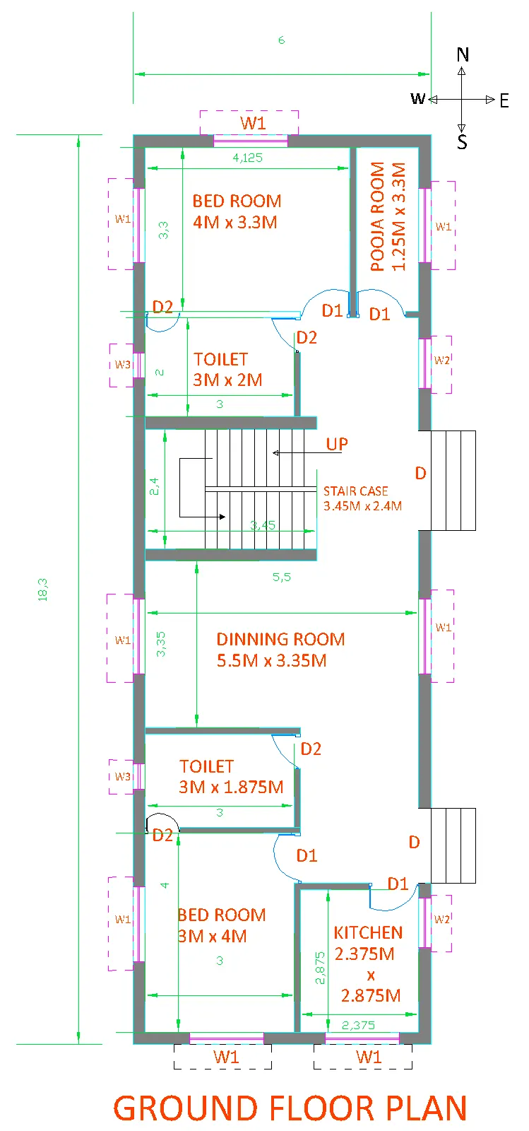
DRAWING PROCEDURE FOR GROUND FLOOR PLAN:-
STEP-1
- Draw a plot of 18.3m X 6m and give direction map to show it's orientation.
STEP-2
- Consider ouside wall thickness is 250mm (or 0.25 meter) and inner wall thickness is 125mm (0.125 meter).
- Create two bedrooms of size (4M X 3.3M), facing north-west and (3M X 4M) facing south-west.
- Create two toilets of size (3M X 2M) facing west direction and (3M X 1.875M) facing west.
- Draw a kitchen of size (2.375M X 2.875M) facing south-east direction.
- Draw a dinning room of size (5.5M X 3.35M) facing west.
- Draw a pooja room of size (1.25M X 3.3M) facing north-east.
- Draw a stair case of size (3.45M X 2.4M) facing west. ( Povide riser 150mm and tread 250mm).
- Provide door sizes D1= 1m X 2.1m, D2= 0.7m X 2.1m ( With help of block you can create suitable doors and add another command "BEDIT" then flip that door as per suitability)
- Provide window sizes W1= 1.5m X 1.2m, W2= 1m X 1.2M, W3= 0.5m X 0.5m.
- Create two entrances of size 2m X 2.1m both are facing east, riser is 150mm and tread is 300mm.
- Write text with the command of "MTEXT" as per suitable font size and text style.
- Create different layers and assign different colours for the visibility and segregate of different components in building.
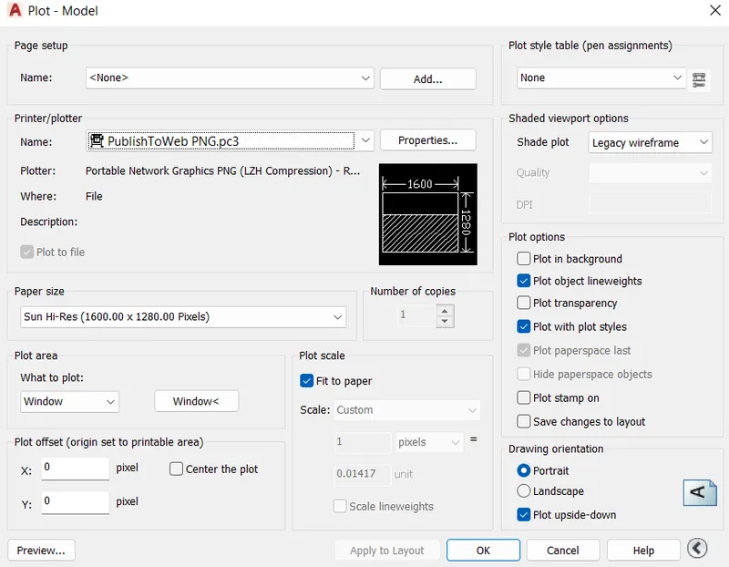
- With the help of "PLOT" command save the drawing in suitable format.
FINAL SKETCH OF GROUND FLOOR PLAN:-
DRAWING PROCEDURE FOR FIRST FLOOR PLAN:-
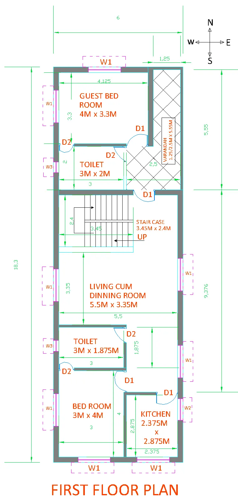
- Consider ouside wall thickness is 250mm (or 0.25 meter) and inner wall thickness, parapet wall thickness is 125mm
(0.125 meter).
- Draw a direction chat to denote North, South, East and West directions.
- Create guest bedrooms of size (4M X 3.3M), facing north-west and another bed room (3M X 4M) facing south-west.
- Create a varanda of size (1.25/2.5M X 5.549M) facing north-east and east.
- Create two toilets of size (3M X 2M) facing west direction and (3M X 1.875M) facing west.
- Draw a kitchen of size (2.375M X 2.875M) facing south-east direction.
- Draw a dinning room of size (5.5M X 3.35M) facing west.
- Draw a pooja room of size (1.25M X 3.3M) facing north-east.
- Draw a stair case of size (3.45M X 2.4M) facing west. ( Povide riser 150mm and tread 250mm).
- Provide door sizes D1= 1m X 2.1m, D2= 0.7m X 2.1m ( With help of block you can create suitable doors and add another command "BEDIT" then flip that door as per suitability)
- Provide window sizes W1= 1.5m X 1.2m, W2= 1m X 1.2M, W3= 0.5m X 0.5m.
- Write text with the command of "MTEXT" as per suitable font size and text style.
- Use "HATCH" command to fill
- Create different layers and assign different colours for the visibility and segregate of different components in building.
- With the help of "PLOT" command save the drawing in suitable format.
FINAL SKETCH OF FIRST FLOOR PLAN:-
DRAWING PROCEDURE FOR SECTION:-
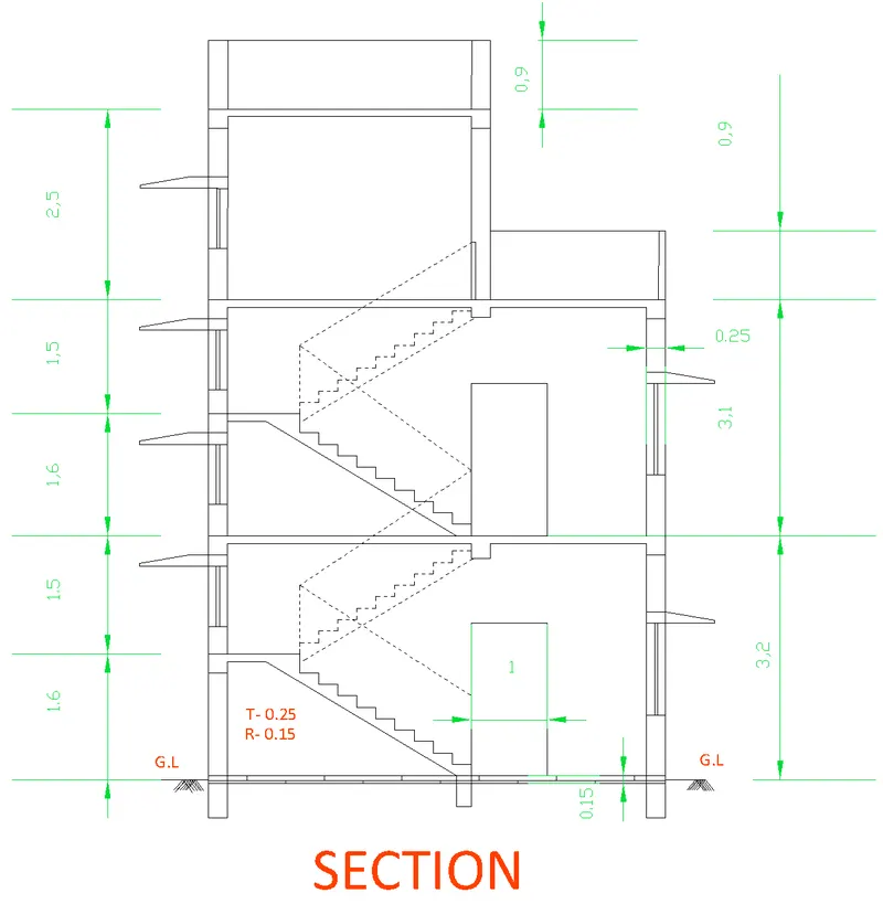
- Draw construction lines from column and stair location to draw a section by command "XL"
- Then provide ground floor p.c.c and brickwork thickness 150mm.
- Give ground floor height 3.2m and first floor height as 3.1m.
- Provide tie beam size as 250mm X 300mm and lintel beam size as 150mm X 250mm.
- Considered main slab thickness as 100mm.
- Provide waist slab thickness as 100mm.
- Consider riser as 150mm and tread as 250mm.
- Provide door sizes D1= 1m X 2.1m
- Draw chajja over windows from lintel, consider chajja thickness as 75mm and width 500mm.
- Write text with the command of "MTEXT" as per suitable font size and text style.
- With the help of "PLOT" command save the drawing in suitable format.
FINAL SKETCH OF SECTION:-
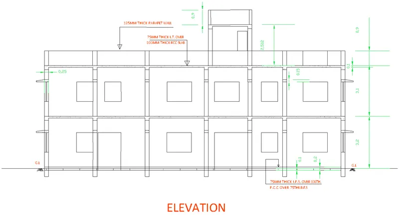
DRAWING PROCEDURE FOR ELEVATION:-
- Draw construction lines from east side location to draw an elevation by command "XL"
- Then provide ground floor p.c.c and brickwork thickness 150mm.
- Give ground floor height 3.2m and first floor height as 3.1m and stair room height as 2.5m.
- Consider parapet wall height as 900mm.
- Provide tie beam size as 250mm X 300mm and lintel beam size as 150mm X 250mm.
- Considered main slab thickness as 100mm.
- Draw chajja over windows from lintel, consider chajja thickness as 75mm and width 500mm.
- Provide door sizes D1= 1m X 2.1m and window sizes as W1= 1.5m X 1.2m, W2= 1m X 1.2M.
- Measure dimensions by commanding "DIMLINEAR".
- Write text with the command of "MTEXT" as per suitable font size and text style.
- With the help of "PLOT" command save the drawing in suitable format.
FINAL SKETCH OF ELEVATION:-
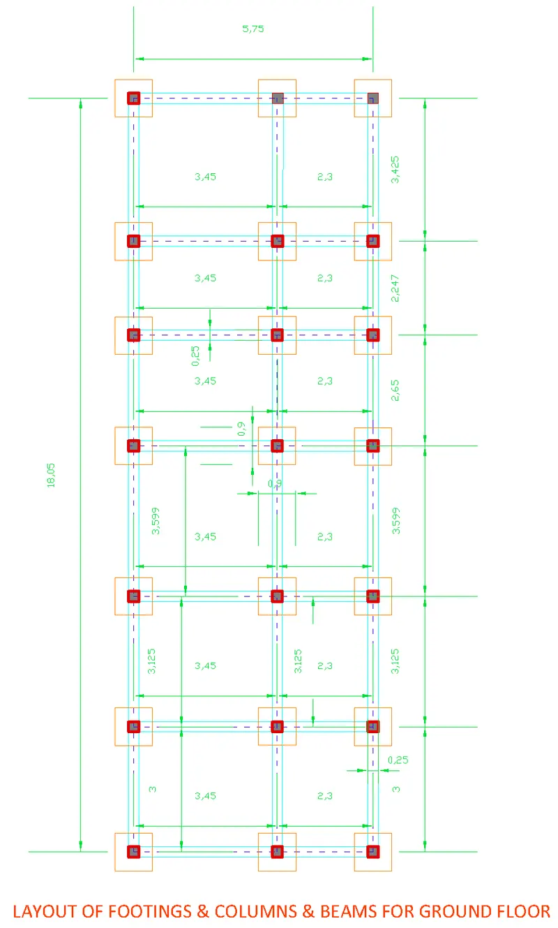
DRAWING PROCEDURE FOR LAYOUT OF FOOTING, COLUMN AND BEAMS ON GROUND FLOOR:-
- Draw central lines in between walls and choose style as "ISO Dash".
- Consider size of footing as 900mm X 900mm and column size as 250mm X 250mm.
- Also consider size of beam as 250mm X 350mm.
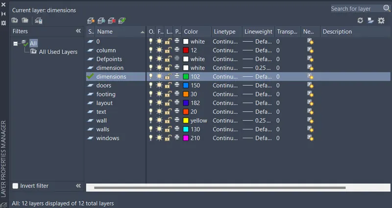
- Use different layers with different colours as shown below.
- Measure dimensions by commanding "DIMLINEAR".
- Write text with the command of "MTEXT" as per suitable font size and text style.
- With the help of "PLOT" command save the drawing in suitable format.
FINAL SKETCH OF GROUND FLOOR LAYOUT:-
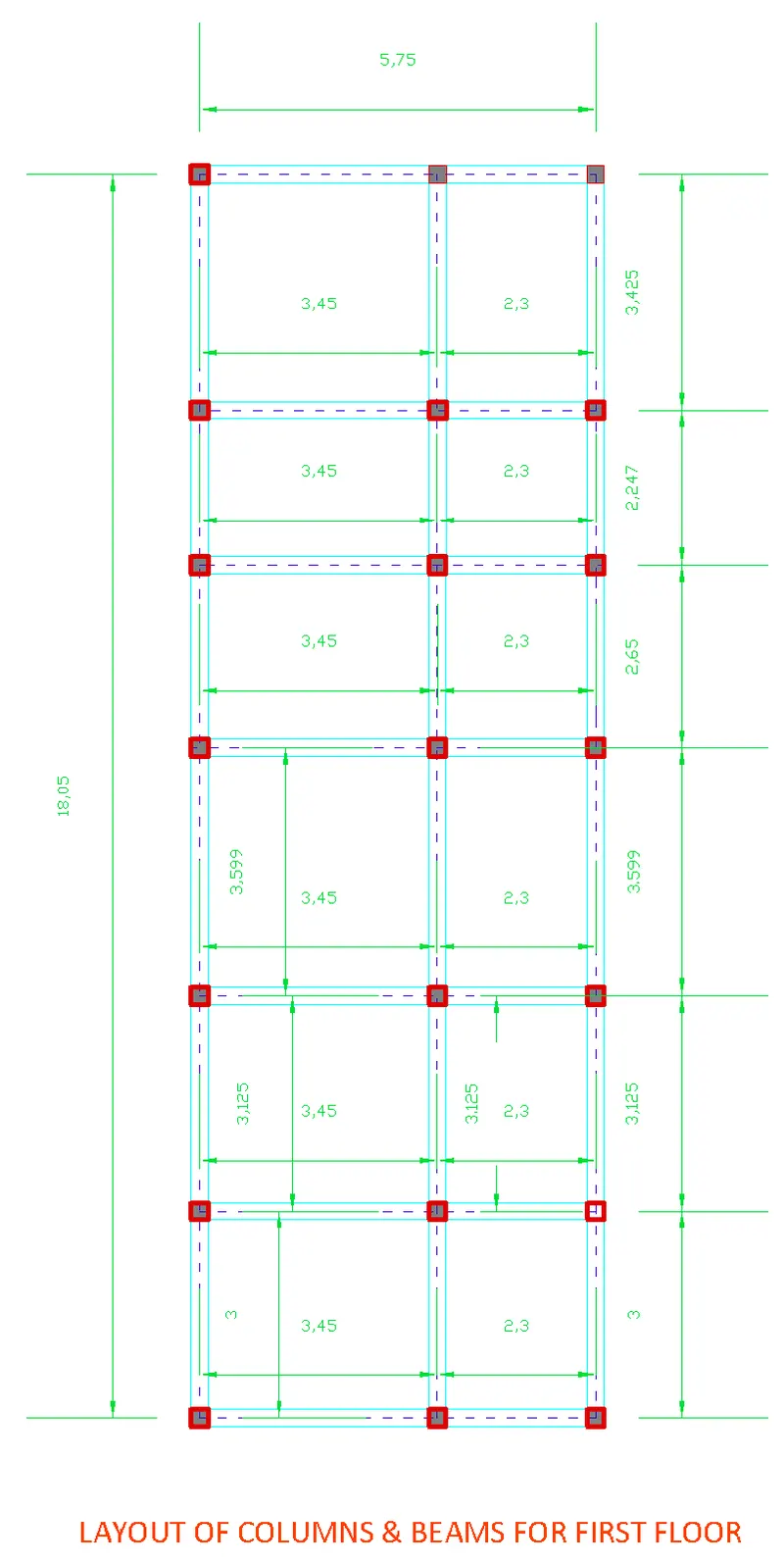
DRAWING PROCEDURE FOR LAYOUT OF FOOTING, COLUMN AND BEAMS ON FIRST FLOOR:-
- Draw central lines in between walls and choose style as "ISO Dash".
- Consider size of column size as 250mm X 250mm.
- Also consider size of beam as 250mm X 350mm.
- Use different layers with different colours as shown below.
- Measure dimensions by commanding "DIMLINEAR".
- Write text with the command of "MTEXT" as per suitable font size and text style.
- With the help of "PLOT" command save the drawing in suitable format.
FINAL SKETCH OF FIRST FLOOR LAYOUT:-
RESULT:-
FINAL SKETCH OF ARCHITECTURAL PLAN OF PLOT.
FINAL SKETCH OF ARCHITECTURAL PLAN OF GROUND FLOOR.
FINAL SKETCH OF ARCHITECTURAL PLAN OF FIRST FLOOR.
FINAL SKETCH OF ARCHITECTURAL SECTION.
FINAL SKETCH OF ARCHITECTURAL ELEVATION.
FINAL SKETCH OF LAYOUT OF FOOTING, COLUMN AND BEAMS ON GROUND FLOOR.
FINAL SKETCH OF LAYOUT OF COLUMNS AND BEAMS ON FIRST FLOOR.