Project 1 _Creating an Architectural plan for the provided plot size and develop relevant basic structural drawings
Aim-To draw a design residential building with floor plan, elevation, section and footing plan with column and beam details.
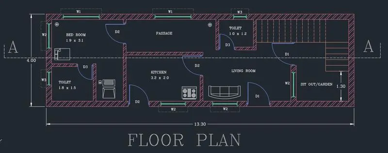
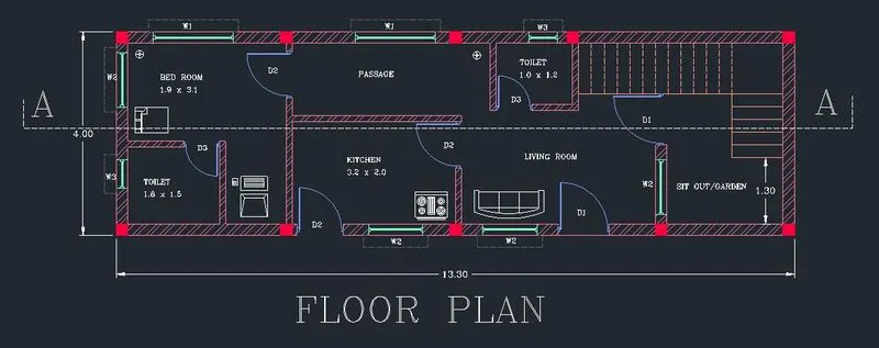
Introduction-The residential plan has east facing orientation and plot size is 18.3mx6m. And it is single storey residential building. The drawings provided are floor plan, front elevaion, section, column an footing plan.
Procedure-
-Set unit in decimal with precision zero
-Set limit, dimension style D enter, i created new Roman style and text font style also the same with fit scale 10 unit.
-Sketch raw diagram which give information about built up area of building and what is the distance from road to construct the building and setback also provided. All of this are done by line and text command.
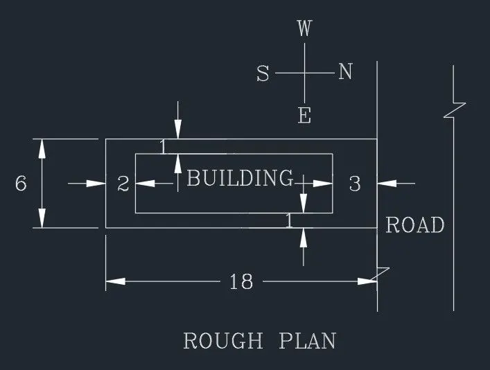
-Now start drawing with construction horizontal and vertical line XL enter
-Create corner lines by trimming left side line and downward line
-Take a offset of 0.23m as a outer wall thickness and start drawing from left to right,downward to upward by taking offset as per dimensions
-For stair case, Tread=0.25m Riser=0.17m Width=1m, And for landing 1m , In first flight 5 steps and in 2 nd flight 12 steps which show by dotted lines.
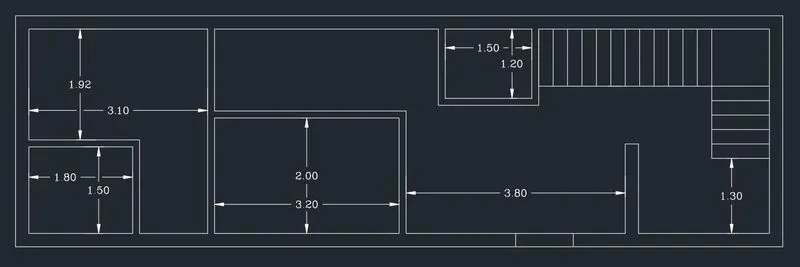
-Now create opening for doors as per dimension by taking offset
-Create block of doors with respective their sizes and windows also and then insert in plan.
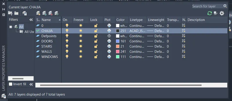
-Then provide chajja for windows
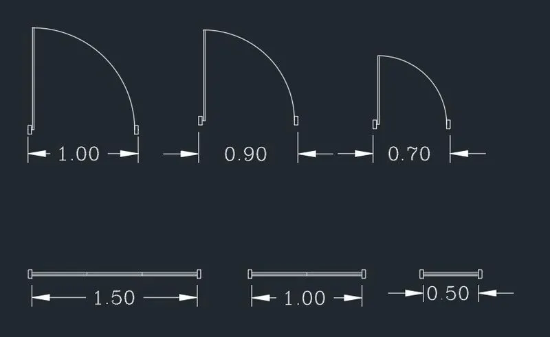
-Now insert a text DT enter give names to every rooms
-Now create layer LA enter and give it to that particular icomponents.
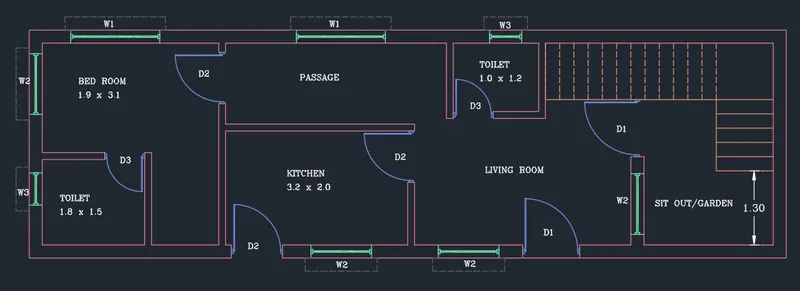
-H enter for hatching, select ANS 132 for brick work with scale 0.8
-ADC enter for design center and insert furnitures in plan.
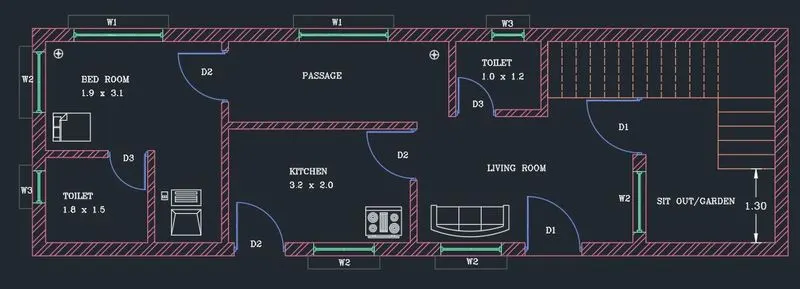
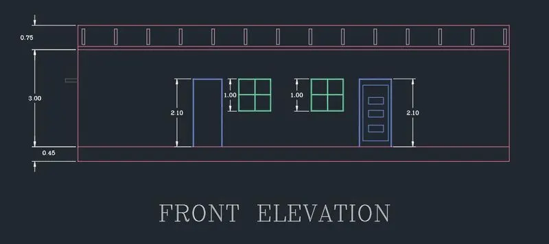
-Now to draw elevation of plan project the lines by construction line vertically
-Draw horizontal construction line as a GL
-Take offset 0.45m from GL for plinth level
-Now from plith level 3m offset as building height and from this take offset of 0.75m for parapet wall.
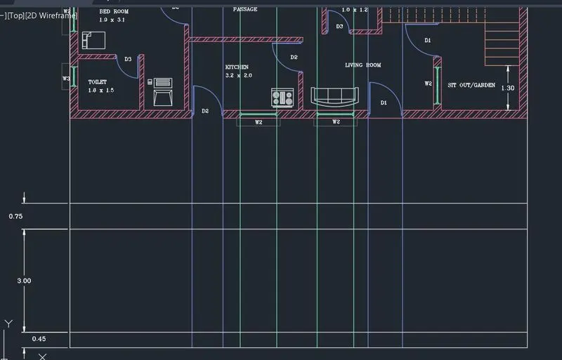
-Trim extended lines.
-To draw door projection give height 2.1m and window size is 1.5m
-Draw sunshade also at a lintel level
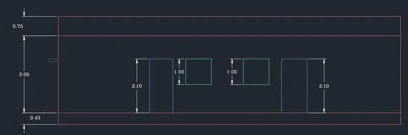
-For entrance door take offset of 0.02m inside as a frame of door and 0.17m inside another offset
-For window take 0.02 offset and create 2 panels
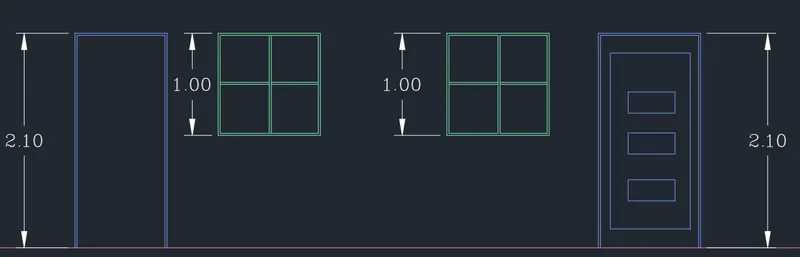
-Give architectural view on parapet wall by creating holes in rectangular shape
-PL enter to show section line and layer is in dotted line
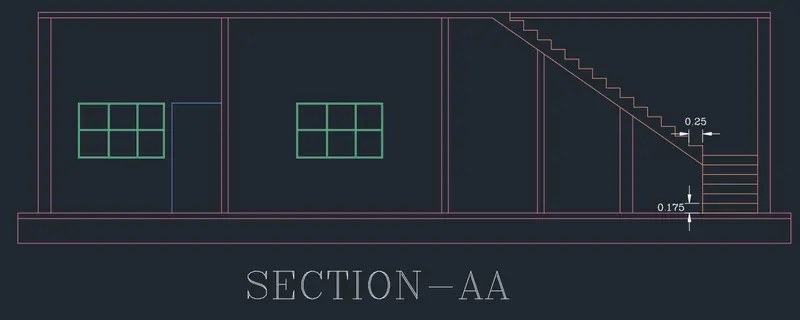
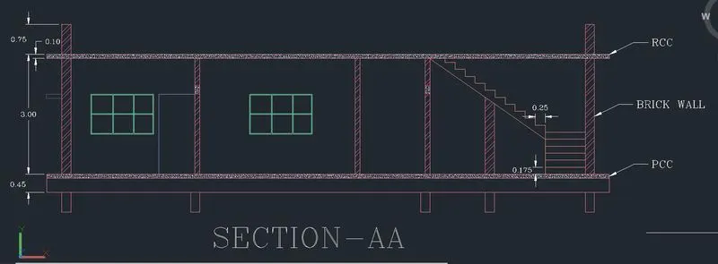
-Section AA
-To draw section-AA take projection of elevation horizontally as a height of building
-In section, the portion is visible which is above the section line. Take projection from floor plan to draw exact location of wall, doors, windows and stairs.
-After taking projection trim the unwanted lines
-To draw stair case, section line cut the first flight so take riser 0.175m offset and then for 2 nd flight take riser and tread 0.23m upto slab
-To draw door and windows take projection, trim lines
-Now place columns, to draw columns take rectangle command @0.23,0.23
-Place columns at corner of rooms and and at intersection of walls.
-Make seprate layer for column and hatch it.
-Show column in section, so project the lines from floor plan to section trim unwanted lines
-In section 0.1m slab with hatching AR-CONC scale of 0.01 is provided
-Take offset of 0.45m from ground level and that will be our plinth level
-Intermediate column also show with same hatch i.e. AR-CONC
-Dimensions are provided for better reference
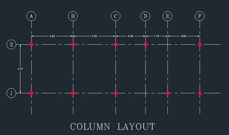
-For structural drawing column layout and footing layout provided
-For column layout, turn off all the layers except walls and copy that plan
-Now delete the walls also and draw center line through the center of columns

-Now mark the grid lines, in x-direction ABCD etc and in y-direction 123 etc
-Draw circle and insert text in it
-Provide dimension
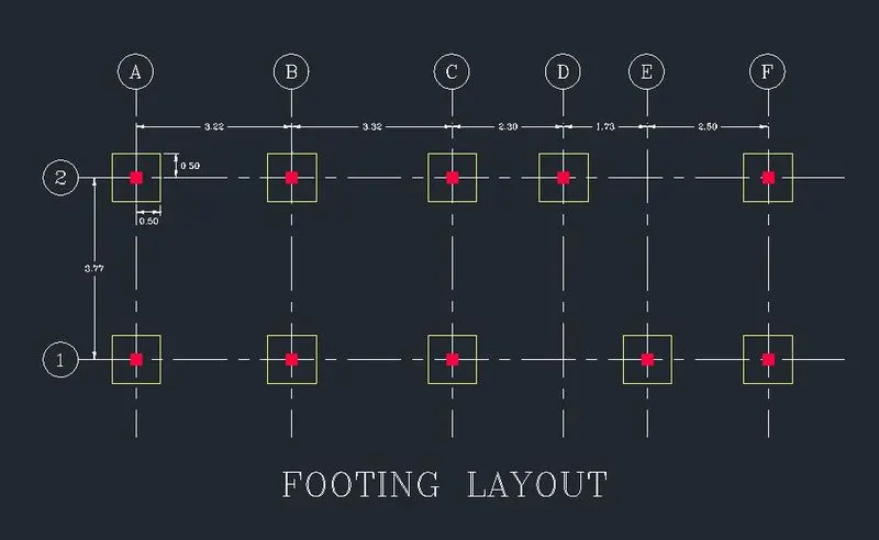
-For footing layout, isolated footing is provided with size 1mx1m
-Draw rectangle of @1,1 and place it at center of column
-Make a layer for footing and apply it
-Mark dimension between footing and column
Result-Architectural and structural plan of single storey building is drawn
Architectural drawings provided are-Floor plan
-Section-AA
-Front elevation
Structural drawing provided are-Column layout
-Footing layout.