Project 1 _Creating an Architectural plan for the provided plot size and develop relevant basic structural drawings
AIM:
Design and Draft a layout of a residential building with the following details:
a. Plot Size: 60’x20’(18.3m x6m)
b. Orientation- Facing East
c. Develop the following: 1. Architectural Drawing (Floor Plan, Elevations, and Sections)
2. Structural Drawing (Column, Bean, Footing Plan)
INRODUCTION:
plan, section and elevation are different types of drawings use by architect to graphically represent a building design and construction. a plan drawing is a drawing on a horizontal plane showing a view from above. an elevation drawing is a drawn on a vertical plane showing a vertical depiction. a section drawing is also a vertical depiction, but one that cuts through space to show what lies within.
structural drawings are commonly known as civil engineering drawings. these drawings depict the bits and pieces of a structural skeleton which are used as guide by the site engineers and workers.
PROCEDURE :
1. architectural drawings.
a) floor plan
- type un and set unit to engineering inches
- keep ortho mode on
- make rec using line command having size 20' x 60'
- make layers for different component
- type offset and give offset of 9" to both vertical lines and top horizontal line
- give offset of 4.5" for bottom line
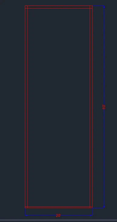
- draw horizontal offset from bottom line which is offset line of 4.5"
- give offset of 4' and then 4.5" offset
- then give the offset of 9' then 4.5" offset
- then give the offset of 5' then 4.5" offset
- then give the offset of 11'4"' then 4.5" offset
- then give the offset of 11' then 4.5" offset
- then give the offset of 16'8" then 4.5" offset
- now make offset from top horizontal line which is oofset line of 9"
- give offset of 6'1"' and then 4.5"
- now draw vertical offset from left vertical line which is offset line of 9"
- give offset of 5', 14'2", 18'6", 9'10" and then give 4.5" offset after every line
- make other offset from right vertical line
- give offset of 3' , 4', 6', 9'4" and then give 4.5" offset after every line.
- use trim and fillet command erase unwanted line
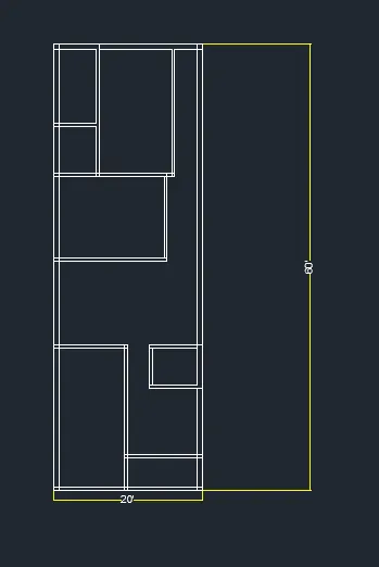
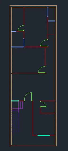
- give the openings to the rooms, sliding glass doors and windows tomots rooms, window, and draw staircase
- take width of staircase as 3'
- take tread - 10" and riser-7"
- using 10" tread make 14 no of offset 2 offset toward west direction and 12 towards south dirction
- for door openings, take sizes of door D,D1,D2
D- 3'6" X 7'
D1- 3' X 7'
D2- 2'6" X 7'
- using this width give DOOR opening to rooms
- draw the differenr door size symbol as shown in fig and paste it
- Take window sizes
- W= 5' X 3'6''
- W1= 3'X 3'6"
- draw the symbol of windows as shown in fig
- mark the window at kitchen and living room
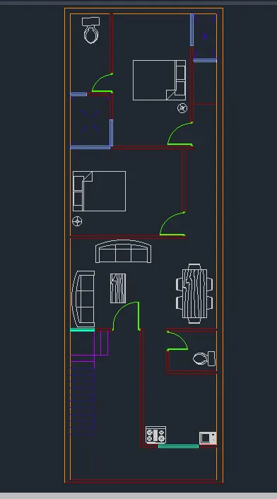
- type adc command to use some in build blocks in autocad such as bed, oven, sofa, dining table, sanitary basin etc
- type adc command go to house designer then select blocks and selet items and paste on drawing
- 
- name the drawing
- use mtext command and name the door, window, and name of rooms with their sizes
- use dimlin command for showing width of passage
- show the north direction
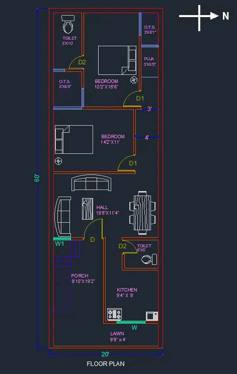
b) Elevation :
- for elevation take projection lines
- use xline command mark the projection
- take plinth height as 1' from ground level , sill height 3', lintel height 7, slab height 10' from plinth level and parapet 3' from slab level
- make horizontal offset from gl using above measurement
 -
-
- using the above projection marking set the doors and windows slab level parapet
- use trim, rec, offset command for it.
- on left side we have provided tower
- tower height 17' from ground level
- make elevation out of it
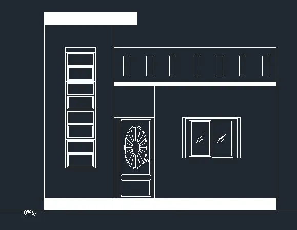
- use layers for different component and give hatching to plinth and tower slab
- type adc command and take blocks of windows and door and paste it.
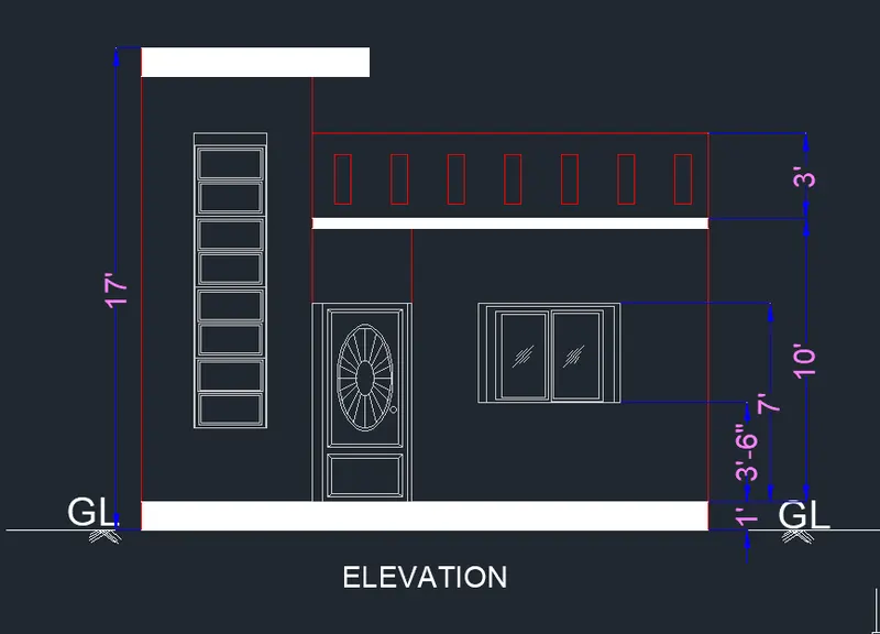
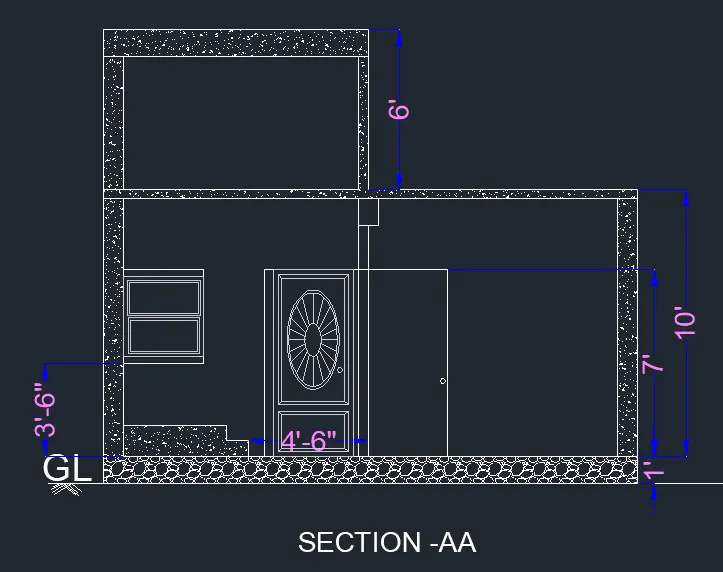
C) Section .
- first we need to mark section line on floor plan
- mark the section line AA on drawing.
- make section line layer use lintype centr line
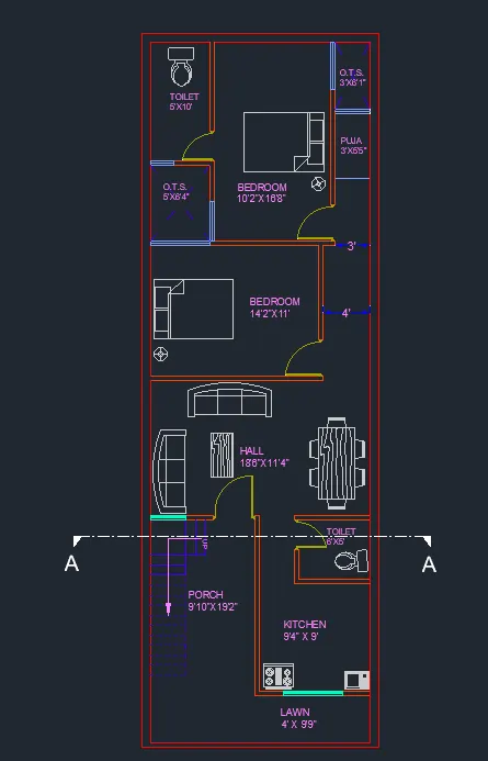
- type xline and draw the projection from every point
- take a horizontal line as a round level
- mark the plinth heigth giving offset of 1'
- from plinth lvl give offet of 3'6", 7', 10',
- for parapet give offset 3' from slab level
- for tower height 6' offset from slab level
- using the projection draw window and door using rectangle command
- draw the staircase cutting in section line
- mark the beam spot using rec command
-select hatch select conc hatch and bolder and hatch the componenet
- type adc command select door and windows block and paste on door and window
- scale command scale adc block
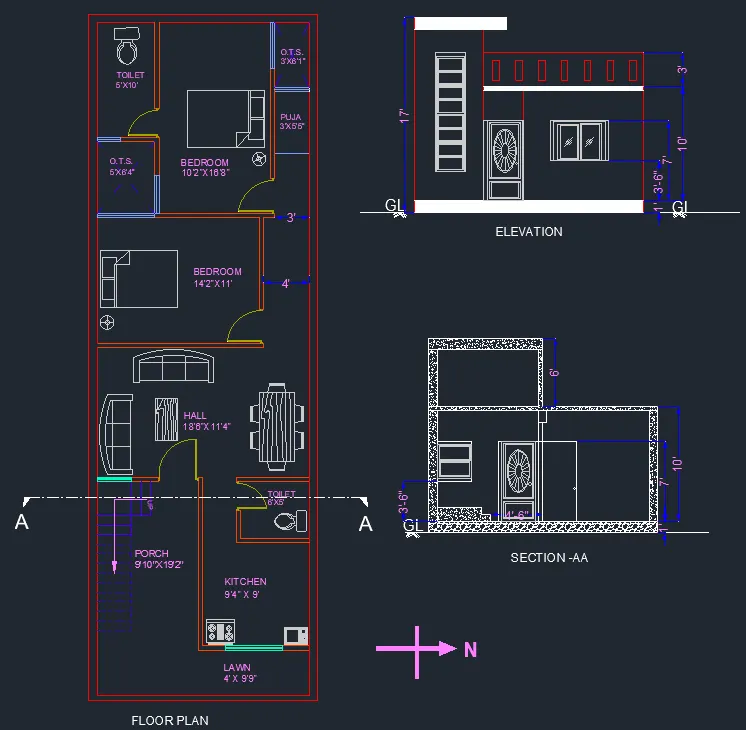
ARCHITECTURAL DRAWING- floor plan, elevation, and section
2.Structural Drawigs .
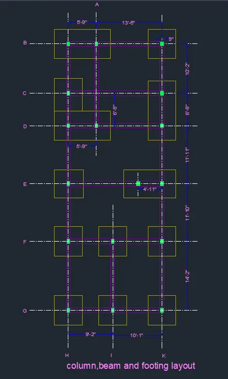
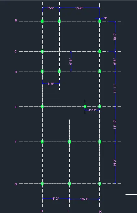
A) Column layout
- make layer of column
- mark the column position by taking refrence of floor plan
- type rec command give dimensions 9" x 1'
- for som places use rotate command to position the column
- use coy command to paste this column at different location
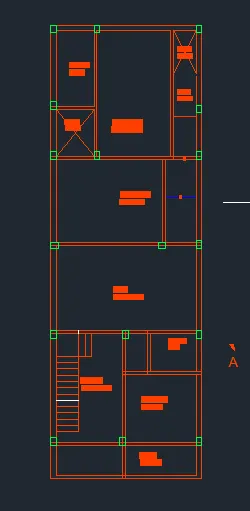
- turnoff the floor plan layers
- use section line layers mark the centre of all the column
- and give the distance using dimlin command
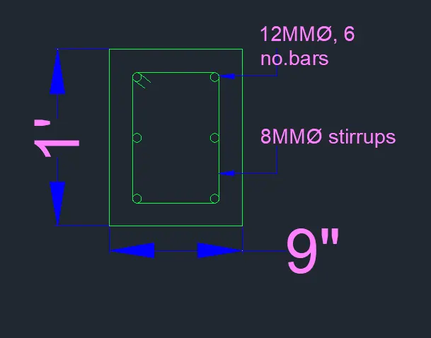
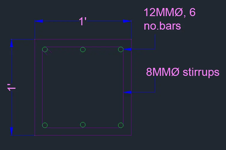
- column details
- type rec command make rectangle of dimensions 9" x 1'
- make 1.57" offset inside the rectangle
- type fillet comaand use radius option and fillet the corner of inner rectngle
- type c for circle command and draw circles
- use mtext for naming and dimlin for dimensions
- type qleader to show the bars
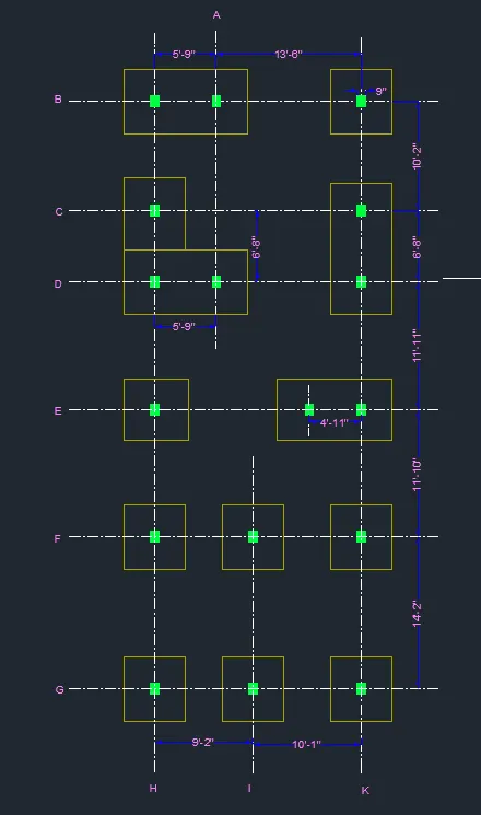
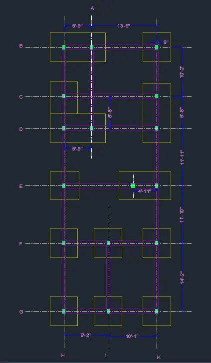
b) Footing layout .
- take column layout drawing
- create new layer for footing
- go to layer properties create new layer
- type o for offset command
- give offset of 2'6" to every column rectangle
- merge 2 column footing wherever required
- used trim and extend command for it.
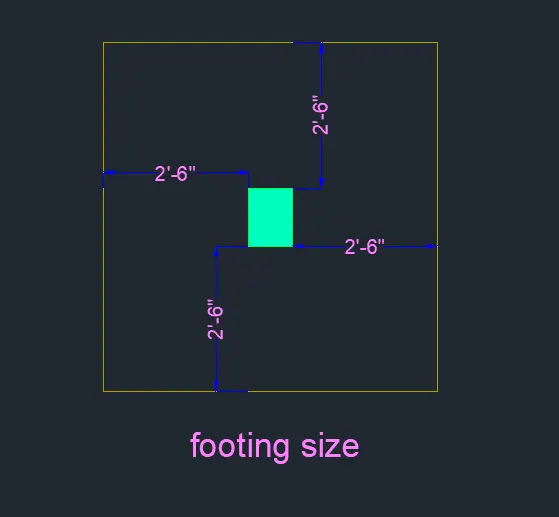
- for layout details
- type rec for rectangle
- specify first corer point select dimensions 2'6" x 2'6"
- use dimlin command to give dimensions
c) beam layout .
- make new layer for beam
- type rec and make rectangle taking refrence of corner point of column
- beam shown in fig
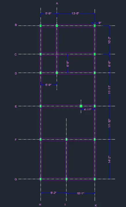
- column details
- type rec command make rectangle of dimensions 1' x 1'
- make 0.98" offset inside the rectangle
- type fillet command use radius option and fillet the corner of inner rectngle
- type c for circle command and draw circles
- use mtext for naming and dimlin for dimensions
- type qleader to show the bars
column, beam and footing layout
RESULT :
we have completed project-1 Creating an Architectural plan for the provided plot size and develop relevant basic structural drawings.We have designed and drafted a layout of residential buildings. orientation facing east and having plot size 20' x 60'.