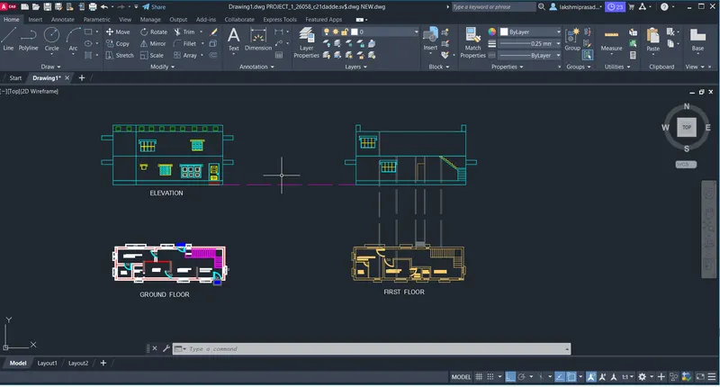
Project 1 _Creating an Architectural plan for the provided plot size and develop relevant basic structural drawings
AIM: To draw
1. Architectural drawing of a building.
a) Plan of a two storey building.
b) Elevation of a two storey residential building.
c) section of a two storey redidential building.
2. Column palnlayout of the building.
Beam plan lauout of the building.
Footing plan layout of the building.
PROCEDURE:
STEP :1 Opening of auto cad and set limits.
- ooen auto cad and select metric as we are draing in cm.
- select the limit and zoom all.
- set the dimensions to decimal units and set the precesion
1. Architectural drawing of a two storey residential building.
A. Plan of residential building.
step :2
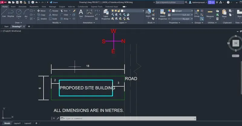
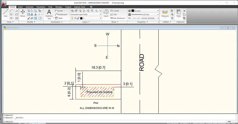
- Draw the plot and give the setback .
- Give the plot size as 18.3m & 6m.
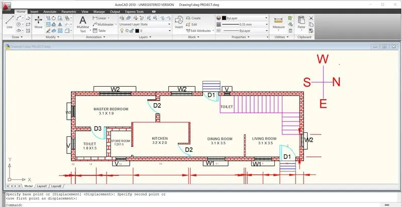
- Mark directions as N,S,E,& W.
- By rectangle draw the plot giving dimensions as 6m, & 18.3m.
- Give set back from th plot front - from the road 3m, 2m, from back yard, 1m from the sides
- The proposed building should be comee from inside setback drawn.
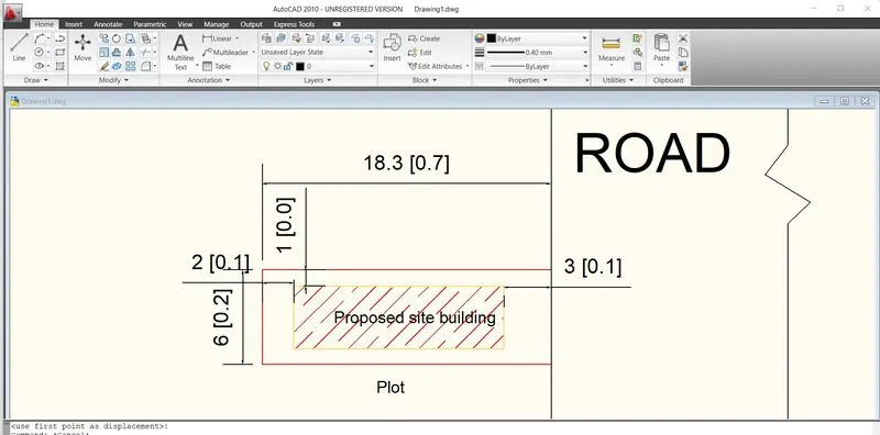
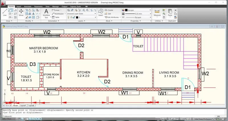
2. Ground floor plan:
step :3 drawing a wall.
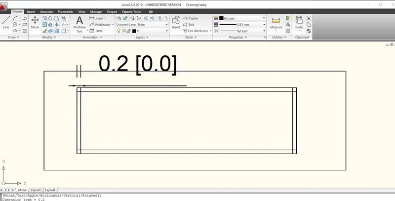
offset 0.23m from boundary after the set back is taken for the wall thickness.
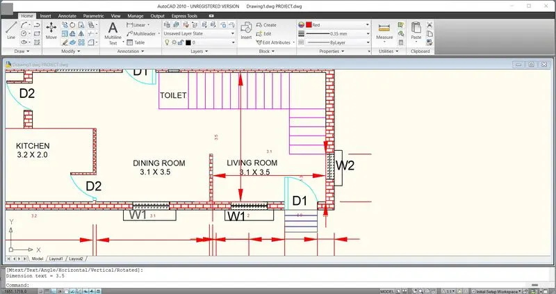
step:4 Drawing Living Room:
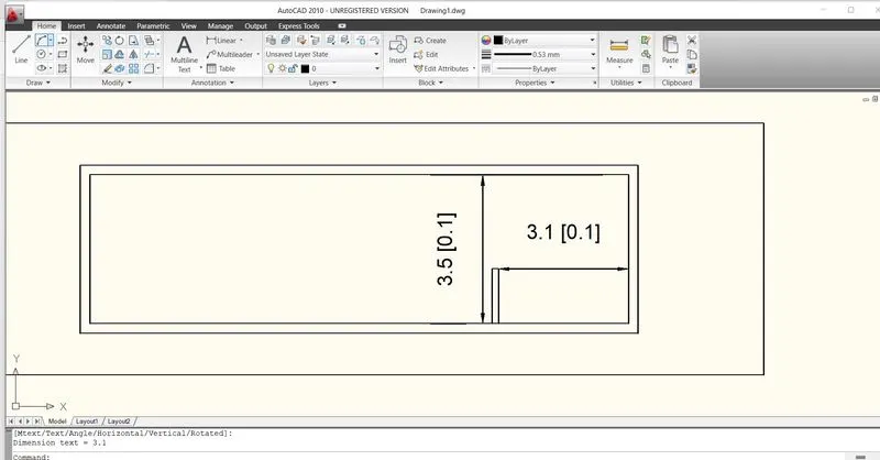
As the orientation given as EAST main door should face EAST.
For living room , give 3.1m offset horizontally from north side wall.
The size of room will be 3.1 x 3.5m.
Opening for main door is creatte by offseting 1m from the wall and trim the same.
Step : 5 Drawing stair case.
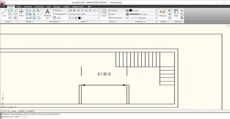
From North wall of living room, drawn an offset of 1m, for the width of the stairs, also offset 1m from the west wall for width of 2nd flight.
stair dimensions: Tread -25cm.
rise -17.5cm
width -1m,
total no of steps = 17 steps.
from 1.3metres from the main door wall, tart drawing the steps.
Draw 5 steps from the first flight with an offset of 0.25m.
Draw landing of 100cm width.
for the second flight steps , again offset 0.25m and draw 12 steps.
step:6 Drawing Dining room
again offset 3.1m from living wall for dining room.
width will be 3.5m.
size of dining room is 3.1 x3.5m.
create a door openig of 0.90m on the west wall of dining room.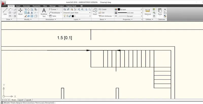
step :7 Drawing common toilet:
Below the stairs ,from opening of doors of dining room,create a wall of 0.12m.
offset 1.5m from the wall and 1m offset to east side.
The size of common toilet is 1.5m x 1.0m.
trim 0.80m from the wall and is given as door opening.
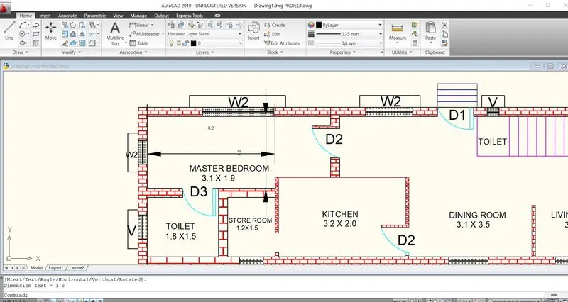
step 8: Drawing kitchen
Offset 3.2m horizontally from dining wall and 2m vertically.
Thes size of kitchen is 3.2 x 2m
trim 0.09 cm for door opening.
Step:9 drawing store:
Drawing horizontal of offset of 1.2m from kitchen wall.
Give vertical offset 1.5m
Give wall thickness of 0.12m
step:10 Drawing master bedroom and toilet:
From the south wall offset 4.5m and width of 1.9m for joining the kitchen wall.
the size of bedroom is 1.9x 4.5m.
Create opening of 0.09cm and ttrim commands.
for toliet draq on offset hor of 1.8m from the store wall.
size of toilet is 1.8 x1.5 m.
Trim the excess line and filter the corners.
create step in the front of main door and door from dinning room.
step 11:
Inserting text : With multiline text, drawing the text box , text height as 0.15m and styles are AL.
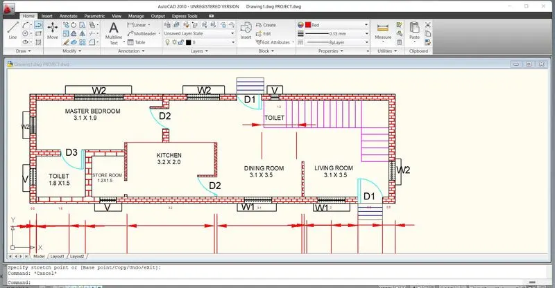
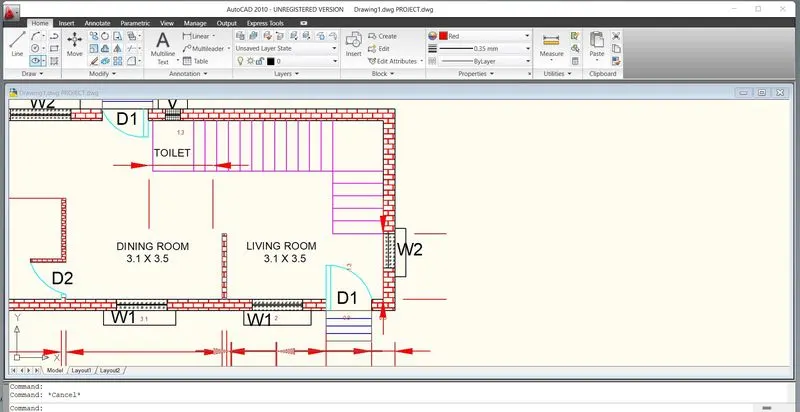
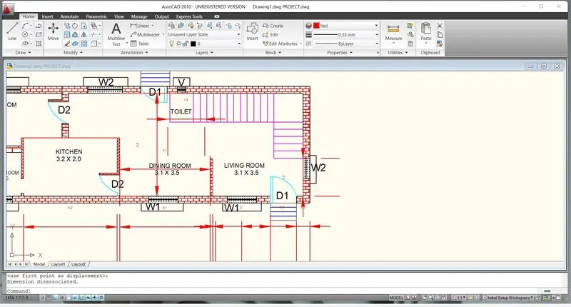

2. FIRST FLOOR PLAN:cm for
STEP 12: Drawing first floor rooms and toilet.
copy the plan and delete all walls except the stairs.
two bedrooms are drawn on top floor.
From the south wall drawn an offset of 3.1m hor 3.5m vertical.
draw toilet of size 1.5m x1.9m.
trim the opening of door 0.9m for room and 0.7m for toilet.
Draw the other room next to first room.
To draw the room offset 3.15m horizontally from the wall of the toilet 2.25m vertically.
draw toilet by offseting 1.2m hor from the room draw and 1.8m vertically.
Draw the partition wall thickness as 0.12m.
Create opening for doors 90cm for room & 80cm for toilet.
next to toilet create as space of 0.88 x 1.8m for placing the ventilator (so that the ventilator dont face the front of the house ) the plumbing works for the toilet.
Rest of the portion is considered as a living area.
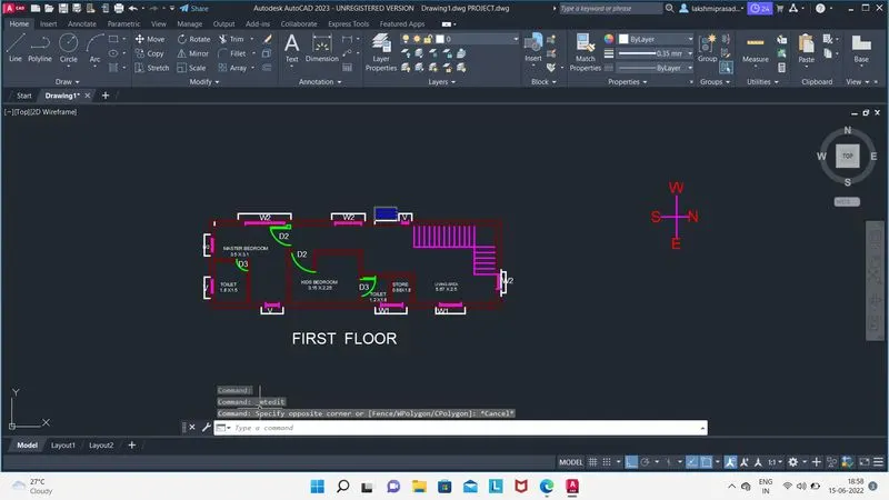
HATCHING:Objects are hatched to show their material property.
hatching is done for brick & open terrace.
ANS132, Scale-2 is used for berick work.
Hatch edit is selected and the colour of hatch is changes to red.
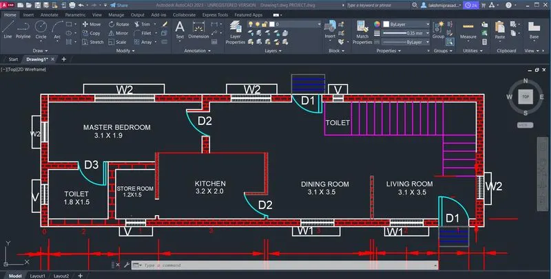
B.Elevation:
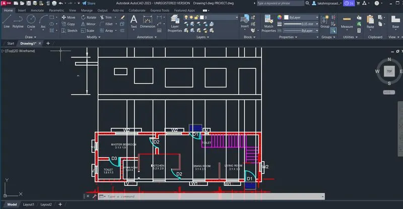
Projecting th e lines to draw the elevation.
Project the wall lines to the top.
Draw an horizontal line.
Offset 0.45m for the plinth level.
Offset 3m for the first floor level.
Again 3m for the second floor level .
Drawing windows and doors in elevation:
For windows and doors project thw windows from the plan and give a height of 1.2m and 1.5m ( for w1 in living & dining) .
for doors project the door and give height of 2.1m.
Project the shades and draw the shades and top of the window level.
Trim off the extension lines and make shutters and plans for doos and windows.
Offset 0.02m for the frame for the doors and windows.
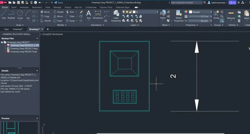
For Di entrance door creatte a rec offset 0.02 another rec offset 0.015m ,and also offset 0.02cm for thickness of corners by line.
For bottom plan draw a rec with same width as top plan and give a thickness of 0.02m by ffseting.
Draw a small rec with thickness 0.02m.
Then copy it for 3 rows and 4 columns.
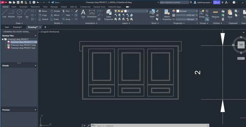
For w1 height 1.50m , draw an offset of 0.02m for the thickness.
draw an rec offseting 0.07m from thee frame and also offset thicckness of 0.02m.
for the bottom panel divide it with height of 0.465m, and offset 0.02m thickness for frame.
Again offset 0.07m from the frame for the shutter give 0.02m thickness.
Repeat it for 3 panels for as its a 3 panel window.
Give the shade at the top of the window.
copy this for the window W1.
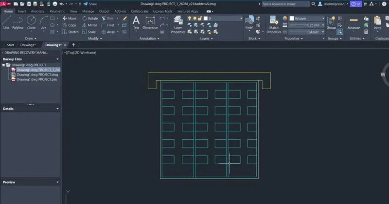
For W1 with aheight of 1.20m,draw the frame of 0.02m thickness.
show the rods of the window provided the shade.
For ventilator draw a height of 0.50m ,and offset for frame 0.02m.
for the first floor projec tthe wall, window, door lines seen infront of the first floor of the plan.
from the floor level mark 2.10m height for the lintel level.
draw the window for that level.
draw window w2 of two panels from the door height to 1.20m.
offset0.02m for the thickenss and show the rods.
copy the window to the other sides also.
sunshade is also drawn.
project 0.75m to top to show the top parapet wwall.
hatch the window with GOAST GLASS scale - 0.01in (v)and 0.05 (w).
copy the window to the other side also.
sunshade is also drawn.
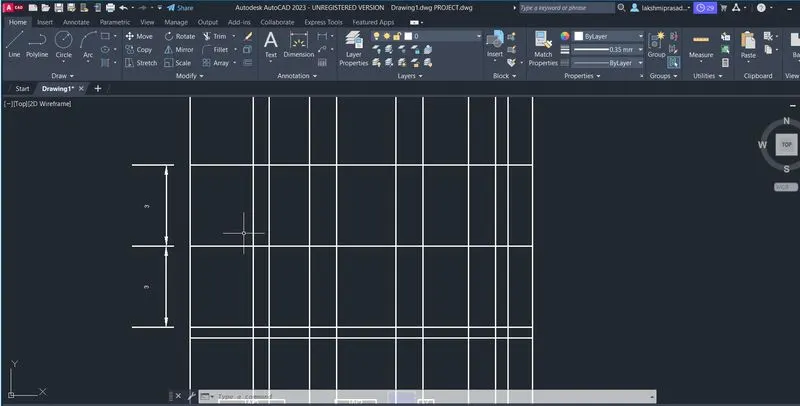
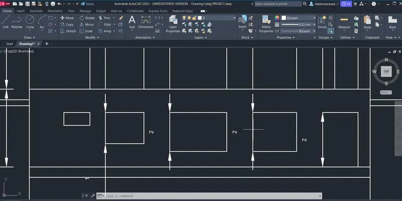
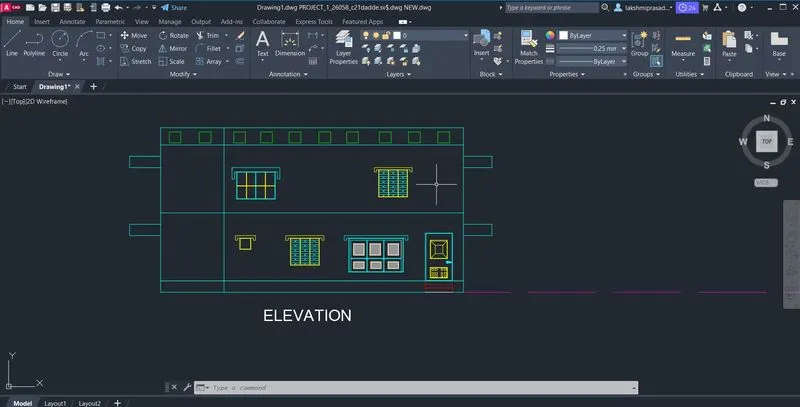
C.SECTION:
Section of 1st floor:
section line of ground floor plan,sextion-AA.
Project the lines from the elvation for the height and from section line of plan for horizontal members.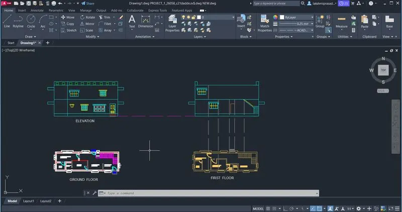
Drawing windows , doors & stairs in section
Draw the window & door which we see after cutting the section lines.
To draw the section of stairs,as the section line cuts throught the stairs,draw the first flight by offserting 0.175m,i.e., the rise.
For second flight we will show the side view with riser ,0.175m & tread 0.25m leading to the slab
For waist slab 10m offseted.
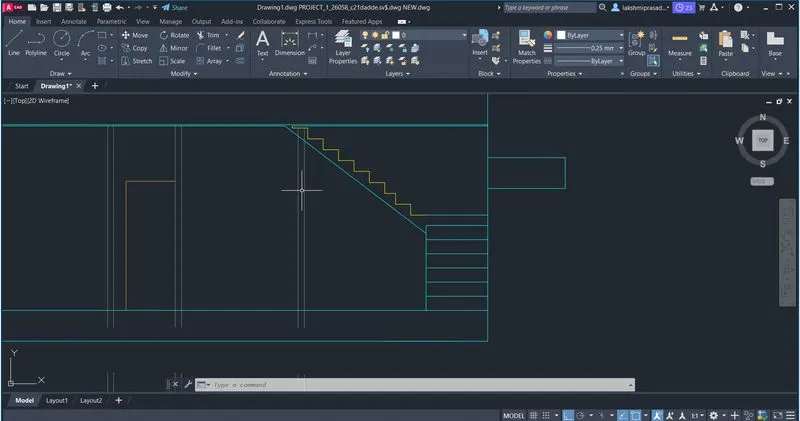
0.15m lintel thickness is shown on the top of every wall and lintel is provided through out .
From the floor 0.10m is offseted to the thickness of the slab.
Draw the section of doors,windows, ventilators where ever the section line cuts
Draw the doors and windows visible for viewing from the section line.
Draw the section of the parapet wall at the top.
Create columns by rectangle command 0.23m x 0.23m place the column in the ground floor plan in all corners and insertion of walls and place all in layers.
copy the same for first floor
In the section project the column from the plan to the section.
structural drawing.
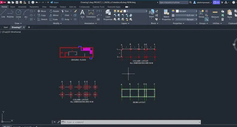
A.column layout: placing of columns.
column of size 0.23m x 0.23m is considered columns are placed in all corners of the wall & insertion of the walls whereever req.
Columns also placed where stair case ends.
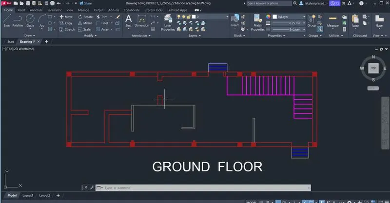
Drawing grisd lines for columns:
Now draw the centre line column from the and anotad tab-centre line.
Make it scale of 0.005.
Delete all walls and stairs.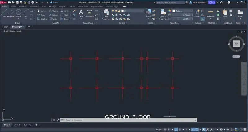
Making of Grid lines.
Now make the grid line as 1,2 in y-direction & A,B,C,D,E,& F in the x-direction.
Create a circle and insert text into for marking.
Dimension between the grid lines are maintained as it is used for making the columns.
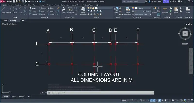
Beam layout:
plinth beam layout: Drawing of plinth beam - primary beams.
To draw plinth beam layout, copy the ground floor with the column.
Plinth beam is provided below all the walls.
Primary beams are provided from one column to the other.
secondary beams are beams conected from the primary beam.
Create a layer from beam.
First connect the columns by beam off width 0.23m, as the wall thickness is 0.23m those are the primary beams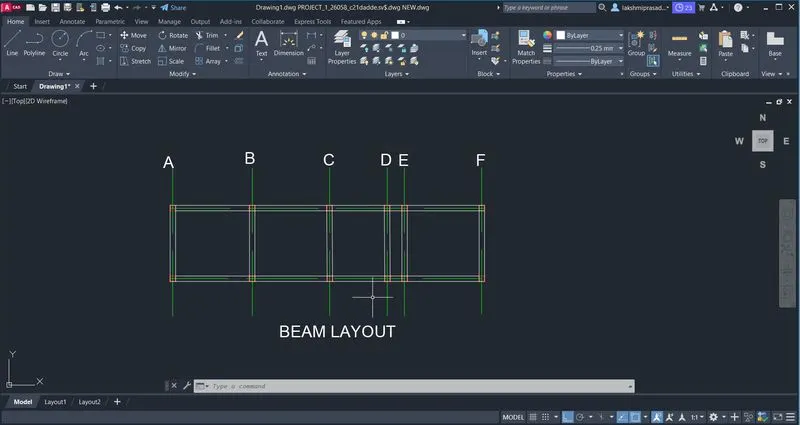
Drawng of plinth - secondary beam
Now connect the other internal walls as beam of width 0.12m, beam to beam connections are secondary beam.
Delete all the walls.
Beam layout for the first floor.
Draw the primary beams of the top floor.
copy the first floor plan with column draw.
Draw beam of width 0.23m connecting all the columns.
Here for stair case a beam is drawn at the landing slab level of the top floor.
Draw seconday beam of top floor.
for all other walls beam of 0.12m is provided t bottom portion of the first floor slab.
C. Footing paln layout:
Drawing of footing.
isolated footing of size 1m x1m is provided.
create a rectangle with dimension 1x 1m , place the centre of rectangle with the centere of the column.
Make a layer footing and place the footing s in that layer.
dimension the distance between footing & column.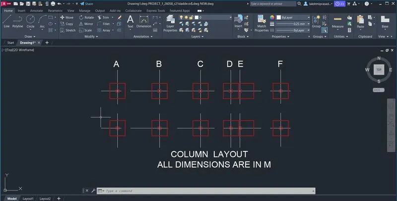
RESULTS: