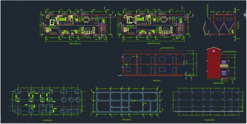
Project 1 _Creating an Architectural plan for the provided plot size and develop relevant basic structural drawings
Creating Architectural Drawings. (Floor Plan. Elevations, and Sections) for a plot size of 60'x20' and developing relevant basic structural drawings (Column, Beam. Footing Plan).
Aim:-
To create Architectural Drawing (Floor Plan, Elevations, and Sections) for a plot size of 60'x20', facing east, and to develop relevant structural drawings (Column, Beam, Footing Plan)
Introduction:-
The desired drawings are created in AutoCAD using various tools. The procedure of drawing is explained in detail with diagrams of each step and the final result is given.
Details provided are:
- Plot Size: 60'x20 (18.3m x6m)
- Orientation: Facing East 1.
Architectural Drawings Procedure:
STEP
- Go to START MENU, select AutoCAD 2023
- In the Command line type in: STARTUP [ENTER]
- Enter new value of startup: 1
- Go to Application Menu and select New .
- In the 'Create New Drawing' dialog box, select 'Imperial' setting.
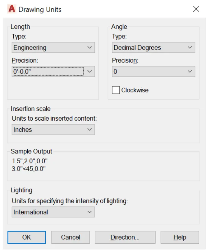
- In the Advanced Setup and select the Engineering unit of of measurement and select precision as '0'-0.0".
- Set the limits by entering LIMITS in the Command tab. The lower-left corner is specified as 0'0",0'0"; and the upper-right corner is specified as 1000',1000'.
- Enter UNITS' command in the command tab. •
- In the Drawing Units dialog box, select Engineering in Type; '0'-0.0" in Precision; and 'Inches in Insertion scale. .
- Click on OK.
STEP 2
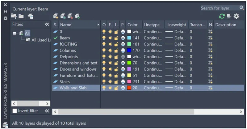
- Click on 'Layer Properties in the Layer panel on the Ribbon.
- Click on 'New Layer' to create the following layers - Doors and windows, Walls and slab, Columns, Beams, footing, Stairs, Furniture and fixtures, and Dimension and Text.
- Specify different colors for the different layers and then close the Layer Properties Manager dialog box.
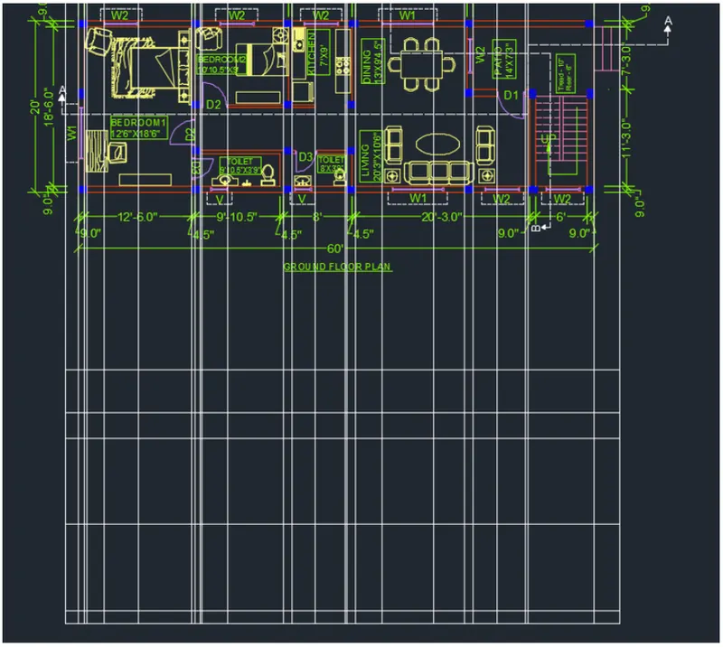
(a) Floor Plan:
STEP 3
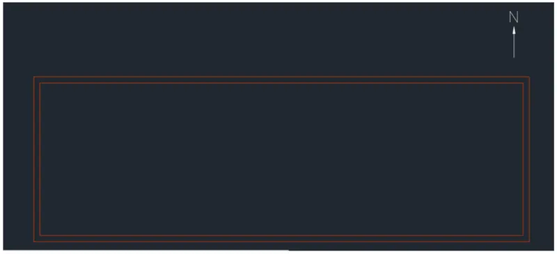
- Enter QL in the comand line and draw a line depicting the north direction.
- Enter DTEXT and type in the letter N.
- Press Esc.
- To begin drawing, select the Walls layer as the current layer in the Layer panel.
- Select the Construction Line tool by entering 'XLINE' command in the command tab.
- Draw two lines, one vertical and the other horizontal, both intersecting at a point.
- Press Esc to cancel the XLINE.
- Select the Trim tool by entering 'TR' command in the command tab.
- Press ENTER
- Select Edge option; and click on No Extend.
- Select the extruted lines.
- Press 'Esc' to cancel the TRIM command.
- Select the Offset tool by entering 'OFFSET' command in the command tab.
- The vertical line is offsetted to a distance of 60'.
- The horizontal line is offsetted to a distance of 20'. Repeat Offset.
- Taking thickness of external wall as 9", enter 9.0" as offset distance in the command line.
- Select both the vertical and horizontal lines of the above drawing.
- Specify the next point on the inside to offset.
- Press 'Esc' to cancel the OFFSET command.
- The unwanted lines are trimmed off using the TRIM command.
- Press 'Esc'.
STEP 4
- Offset command is repeated to create all other walls.
- The bottom inner horizontal line is offsetted to a distance of 6', and the line formed is again offseted to a distace of 9" as is the thickness of the external wall.
- The bottom outer horizontal line is offsetted to a distance of 14', and the line formed is again offseted to a distace of 4.5" as is the thickness of the wall.
- The left inner vertical line is offsetted to a distance of 12', and the line formed is again offseted to a distace of 4.5" as is the thickness of the internal wall.
- Select the Offset tool by entering 'OFFSET' command in the command tab.
- Specify suitable offset distances, to create the different rooms.
- Press 'Esc' to cancel the OFFSET command.
- Then the lines are Trimmed, Erased, Extended and/or Joined to edit the drawing as per requirement.
- For drawing stairs, select the Stairs layer as the default layer in the Layer panel.
- Select the Line tool
- Select the Line tool by entering 'LINE' command in the command tab.
- Draw a line of length 6.
- Press Esc to cancel the LINE command.
- Select the Offset tool by entering 'OFFSET' command in the command tab.
- Specify an offset distance of 10", then click on the desired side.
- Next keep selcting and offsetting the lines for 9 more times to form the stairs.
- Press to cancel the OFFSET command.
- Select the Line tool by entering 'LINE' command in the command tab.
- Draw a line through the mid-point of the 6' long lines created previously to divide the stairs.
- Press Esc to cancel the LINE command.
- Select the Trim tool by entering 'TR' command in the command tab. ENTER.
- Select Edge option; and click on No Extend. Select the unwanted lines.
- Press 'Esc' to cancel the TRIM command.
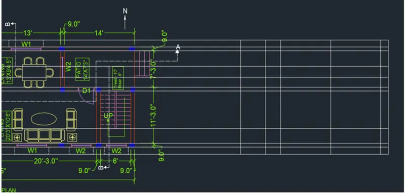
- For the main stairs select the Line tool from the ribbon and draw steps of size Tread and width
- Press 'Esc'
- To draw doors and windows, set the Doors and windows layer as the current layer in the Layer panel.
- Select the Line tool by entering 'LINE' command in the command tab.
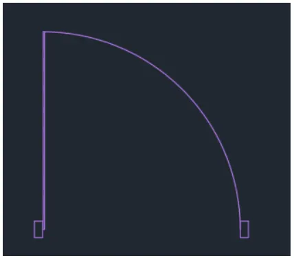
- Door D1 is created at the entrance with a width of 3'3".
- Press Esc to cancel the LINE command.
- Selet the Arc tool from the ribbon, choose the Start, End, Direction option, then draw an arc to represent the swing of the door by specifying the start, end and direction of the arc as suitable.
- To draw doors and windows, set the Doors and windows layer as the current layer in the Layer panel.
- Select the Line tool by entering 'LINE' command in the command tab.
- Door D2 is created at the entrance with a width of 3'.
- Press Esc to cancel the LINE command.
- Selet the Arc tool from the ribbon, choose the Start, End, Direction option, then draw an arc to represent the swing of the door by specifying the start, end and direction of the arc as suitable.
- Select the Line tool by entering 'LINE' command in the command tab.
- Door D3 is created at the entry of each toilet with a width of 2'6".
- Press Esc to cancel the LINE command.
- Select the Arc tool from the ribbon, choose the Start, End, Direction option, then draw an arc to represent the swing of the door by specifying the start, end and direction of the arc as suitable.
- For the windows, Select the Line tool by entering 'LINE' command in the command tab.
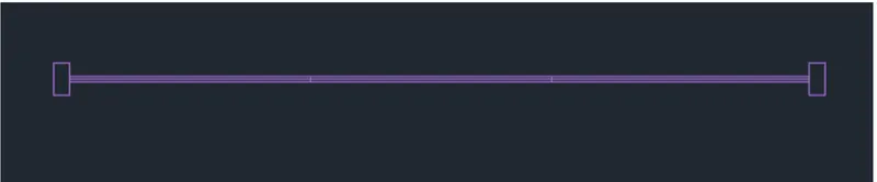
- Window W1 is created with a width of 6'.
- Press Esc to cancel the LINE command.
- Select the Line tool by entering 'LINE' command in the command tab.
- Window W2 is created with a width of 4'.
- Press Esc to cancel the LINE command.
- Select the Line tool by entering 'LINE command in the command tab.
- Ventilator V is created with a width of 2.
- Press Esc to cancel the LINE command.
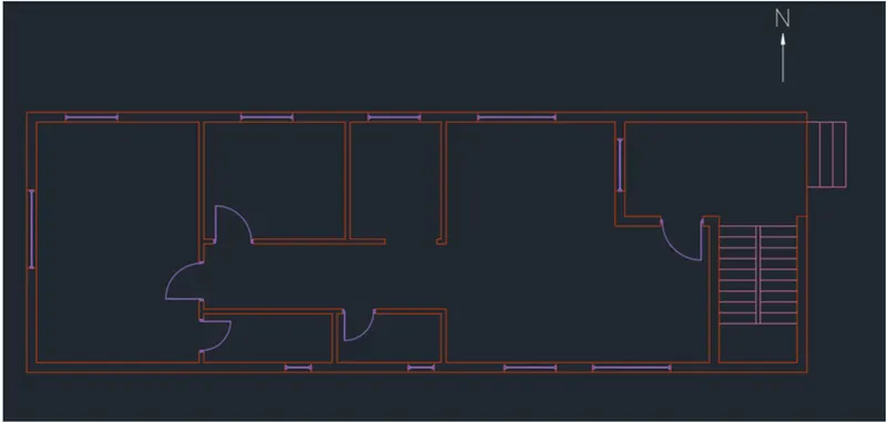
- Convert the doors, windows and ventilator to blocks. Enter B in the command line, specify a pick point, select the objects invidually and assign suitable names to the blocks.
- Enter in the command line, and insert the doors, windows and ventilators to the desired locations with uitable rotation.
STEP 5
- Select the Column layer.
- Select the Rectangle tool by entering 'REC' command in the command tab.
- Draw a column of dimension 1' x 9".
- Press Esc to cancel the REC command.
- Select the Copy tool by entering 'CO' command in the command tab. Copy the colum created before to the desired locations.
- Press Esc.
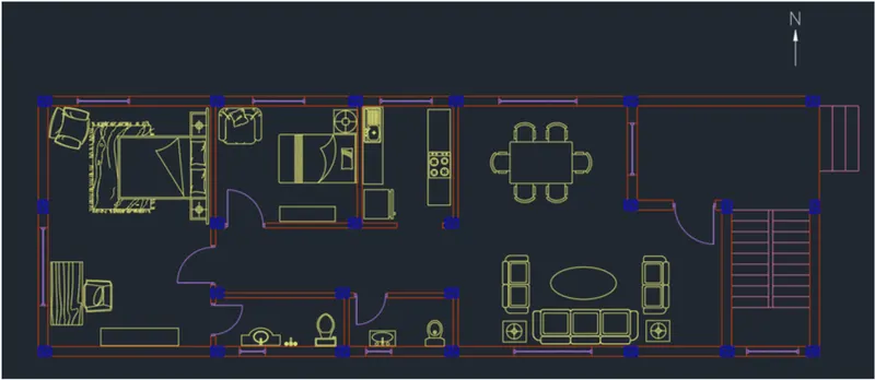
- Enter 'H' in the command line, select AR-CONC pattern and pick point inside the columns.
- Press Esc.
- Select the Furniture and fixtures layer from the Layer panel.
- Enter ADC in the command prompt.
- Fron the DESIGNCENTER dialog box select the required fixtures and appliances and copy them to the drawing sheet.
- Specify the base point, the Scale and position the fixtures and appliances according to the given drawing.
- Select the Rectangle tool by entering 'REC' command in the command tab.
- Draw rectangles to represent cupboards.
- Press Esc to cancel the REC command.
STEP 6
- Select the Line tool by entering LINE command in the command tab.
- Draw lines depicting the chajja. Press Esc.
- Go to Properties and change line type to Dashed.
- Select the Line tool by entering 'LINE' command in the command tab.
- Draw lines depicting the section lines A-A & B-B.
- Press Esc. Go to Properties and change line type to long dash short dash.
- Select the Dimension and Text layer as the default layer in the Layer panel.
- Enter 'DST' command in the command tab to open the Dimension Style Manager dialog box .
- Click on the Modify tab.
- Under the Lines option change the colour of the dimension and extension lines.
- Under the Symbols and Arrows option change the Arrow size to 2.
- Under the Text option change the Text height to 2.
- Click OK. Then click on Set Current and Close the dialog box..
- Select the Dimension tool by entering DIM in the command line.
- Select the first point and second point of the object to be measured, then drag the dimension line to the desired location. Repeat for all the objects to be measured.
- Enter MTEXT command in the command line.
- Specify the start point of text as required.
- Scale the text to the desired size.
- Copy the text box to wherever necessary.
- Enter ED in the command promt and edit the text boxes as required.
- Click Enter and press Esc.
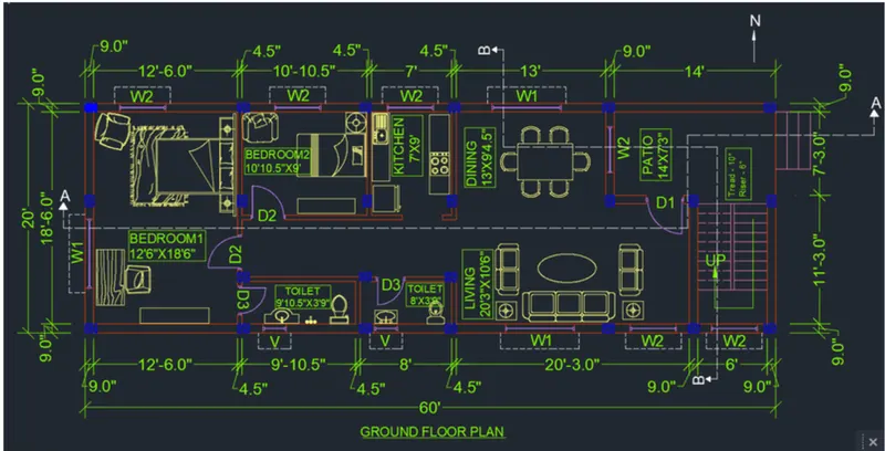
STEP 7
- Select the Copy tool by entering 'co' command in the command tab
- Select the ground floor plan and copy it to a another location.
- Press Esc.
- Delete the stairs at the main entrance.
- Edit the dimensions wherever required.
- Enter ED in the command promt and edit the text boxes as required.
- Click Enter and press Esc
- Select the line tool from the ribbon, and a line for the parapet wall for the balcony on the first floor.
- Press Esc.
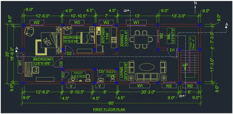
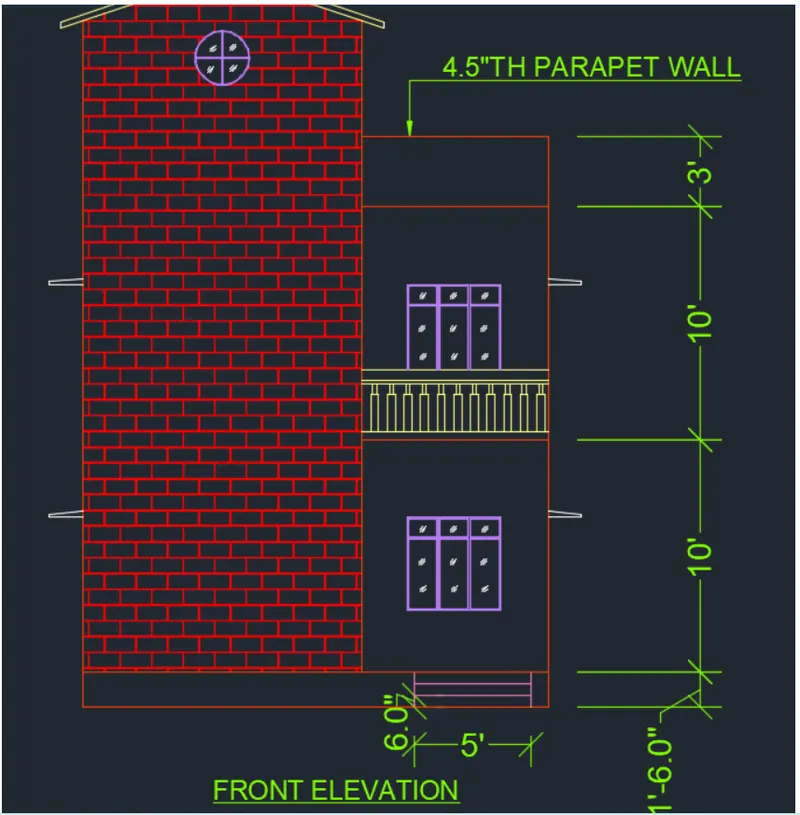
(b) Elevation:
STEP 8
- Select the Construction Line tool by entering 'XLINE' command in the command tab
- Enter V.
- Draw projection lines from the plan created.
- Agnain enter XL, press H.
- Draw a horizontal line at a suitable distance.
- Press Esc
- Select the Trim tool by entering TR command in the command tab
- Press ENTER
- Select Edge option and click on No Extend.
- Select the extruted lines
- Press Esc to cancel the TRIM command
- Select the Offset tool by entering OFFSET command in the command tab.
- offset the horizontl line to distances of re' (plinth height), 10 (floor height), 8 (terrace opening)
- The horizontal Xlines are offsetted to distances as per the given room dimensions and wall thickness
- Press Esc to cancel the OFFSET command.
- Select the Trim tool by entering TR command in the command tab
- Press ENTER
- Select Edge option and click on No Extend.
- Select the extended lines
- Press Esc to cancel the TRIM command.
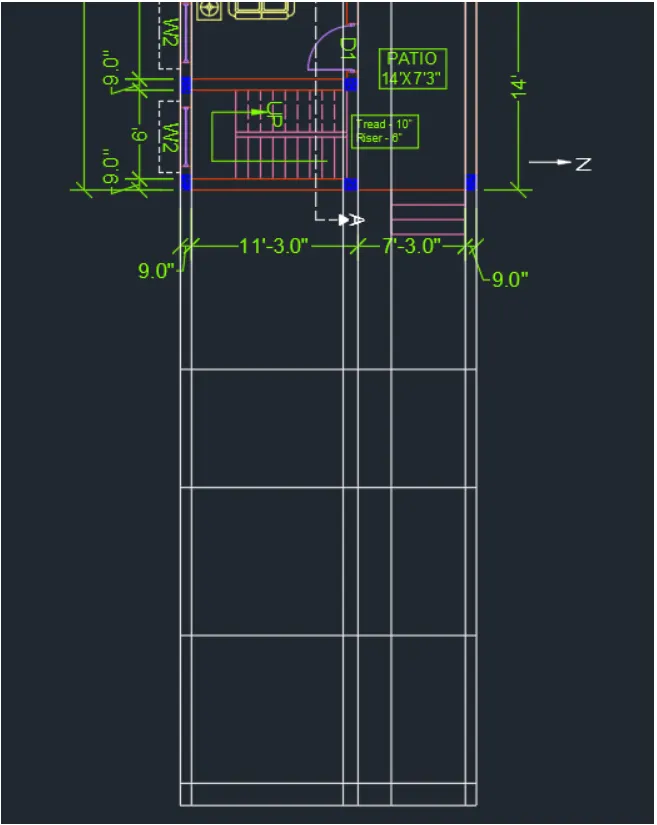
STEP 9
- Select the Trim tool by entering TR command in the command tob
- Press ENTER
- Select Edge option and click on No Extend
- Select the unwanted lines.
- Press Esc' to cancel the TRIM command.
- Select the Offset tool by entering OFFSET command in the command tab
- Create offsets for the windows, the height of windows is taken as is taken as 4
- Press Esc
- Select the Trim tool by entering TR command in the command tab
- Select Edge option; and click on No Extend.
- Select the unwanted lines.
- Press Esc' to cancel the TRIM command.
- Select the Line tool by entering LINE command in the command tob
- Draw the windows
- Press Esc.
- Select the Line tool by entering UNE command in the command tob
- Draw the chaija
- Press Esc..
- Select the line tool by entering LINE command in the command tab
- Draw the railing.
- Press Esc.
- Enter H in the command prompt, select AR-8816C and pick point side the left portionof the bulding
- press ESC.
- Assign the different to their respective layers .
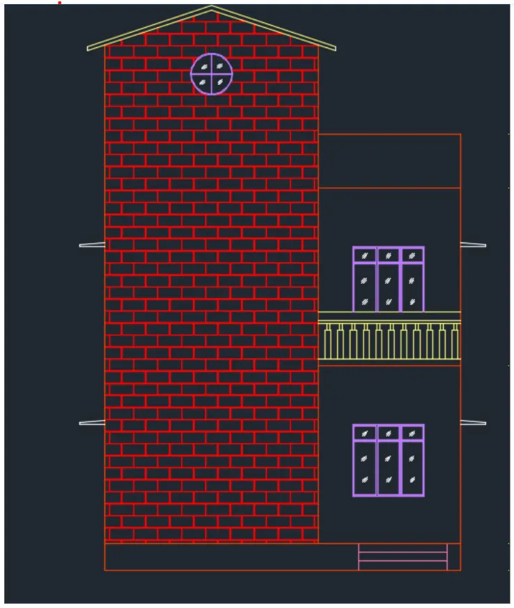
STEP 10
- Select the Dimension tool by entering DIM in the command line.
- Select the first point and second point of the object to be measured, then drag the dimension line to the desired location. Repeat for all the objects to be measured.
- MTEXT command in the command line.
- Specify the start point of text as required.
- Scale the text to the desired size.
- Copy the text box to wherever necessary.
- Enter ED in the command promt and edit the text boxes as required.
- Click Enter and press Esc.
- In Annotate panel, go to Multileader Style Manager, selct the standard option, click on Modify and make necessary changes, click OK and Set current.
- Select the Multileader tool and create multileaders wherever required.
- Save the drawing.
(c) Section A-A:
STEP 11
- Select the Construction Line tool by entering 'XLINE' command in the command tab.
- Enter V.
- Draw projection lines from the plan.
- Enter XL in the command prompt and Click on H.
- Draw a horizontal line at a suitable distance.
- Press Esc.
- Select the Trim tool by entering 'TR' command in the command tab.
- Press ENTER.
- Select Edge option; and click on No Extend.
- Select the extruted lines.
- Press 'Esc' to cancel the TRIM command.
- Select the Offset tool by entering 'OFFSET command in the command tab.
- Create offsets.
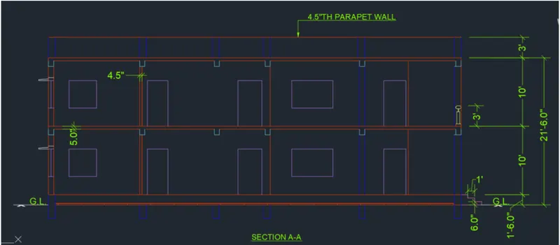
- The horizontal Xlines are offsetted to distances as per the storey height.
- Press 'Esc' to cancel the OFFSET command.
- Select the Trim tool by entering TR command in the command tab.
- Press ENTER.
- Select Edge option, and click on No Extend.
- Select the extended lines.
- Press 'Esc' to cancel the TRIM command.
STEP 12
- Select the Trim tool by entering TR command in the command tab
- Press ENTER.
- Select Edge option and click on No Extend
- Select the unwanted lines.
- Press Esc' to cancel the TRIM command
- Select the Offset tool by entering OFFSET command in the command tab
- Create offsets according to the given drawing for the doors and windows, the height od door is taken as 68 and the height of window is taken to be 4.
- Press Esc.
- Select the Trim tool by entering TR command in the command tab
- Select Edge option and click on No Extend.
- Select the unwanted lines.
- Press 'Esc' to cancel the TRIM command.
- Assign the diferent objects to their respective layers.
- Select the Dimension tool by entering DIM in the command line.
- select the first point and second point of the object to be measured, then drag the dimension line to the desired location. Repeat for all the objects to be measured.
- Enter MTEXT command in the command line.
- Specify the start point of text as required.
- Scale the text to the desired size.
- Copy the text box to wherever necessary.
- Enter ED in the command promt and edit the text boxes as required.
- Click Enter and press Esc.
- In Annotate panel, go to Multileader Style Manager, selct the standard option, click on Modify and make necessary changes, click OK and Set current.
- Select the Multileader tool and create multileader.
STEP 13
- Select the Construction Line tool by entering 'XLINE' command in the command tab.
- Enter V.
- Draw projection lines from the plan.
- Enter XL in the command prompt and Click on H.
- Draw a horizontal line at a suitable distance.
- Press Esc.
- Select the Trim tool by entering 'TR' command in the command tab.
- Press ENTER.
- Select Edge option; and click on No Extend.
- Select the extruted lines. D
- Press 'Esc' to cancel the TRIM command.
- Select the Offset tool by entering 'OFFSET' command in the command tab.
- Create offsets.
- The horizontal Xlines are offsetted to distances as per the storey height.
- Press 'Esc' to cancel the OFFSET command.
- Select the Trim tool by entering 'TR' command in the command tab.
- Press ENTER.
- Select Edge option; and click on No Extend.
- Select the extended lines.
- Press 'Esc' to cancel the TRIM command.
STEP 14
- Select the Trim tool by entering 'TR' command in the command tab.
- Press ENTER.
- Select Edge option; and click on No Extend.
- Select the unwanted lines.
- Press 'Esc' to cancel the TRIM command.
- Select the Line tool by entering 'LINE' command in the command tab.
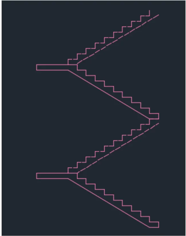
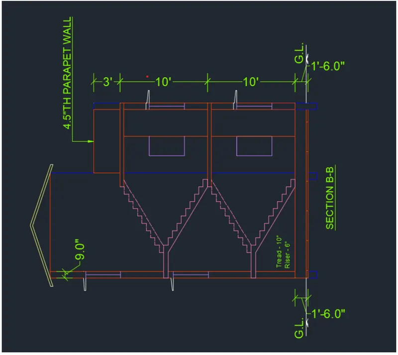
- Draw stairs having rise of 6" and tread of 10".
- Press Esc.
- Select the Copy tool by entering 'CO' command in the command tab.
- Copy the stairs one time to create the flight of stairs.
- Press Esc.
- Select the flight of stairs created and assign it to the Stairs layer.
STEP 15
- Select the Offset tool by entering 'OFFSET command in the command tab.
- Create offsets for the windows, height of windows is 4
- Press Esc.
- Select the Trim tool by entering TR command in the command tab
- Select Edge option; and click on No Extend.
- Select the unwanted lines.
- Press 'Esc' to cancel the TRIM command.
- Assign the diferent objects to their respective layers,
- Select the Dimension tool by entering 'DIM in the command line.
- Select the first point and second point of the object to be measured, then drag the dimension line to the desired location. Repeat for all the objects to be measured.
- Enter MTEXT command in the command line.
- Specify the start point of text as required.
- Copy the text box to wherever necessary.
- Enter ED in the command promt and edit the text boxes as required.
- Click Enter and press Esc.
- In Annotate panel, go to Multileader Style Manager, selct the standard option, click on Modify and make. necessary changes, click OK and Set current.
- Select the Multileader tool and create multileaders wherever required as per the given drawing.
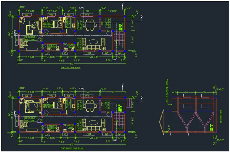
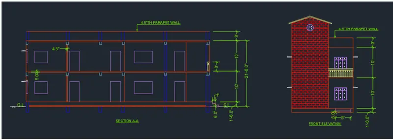
Result :-
2. Structural Drawings
Procedure:
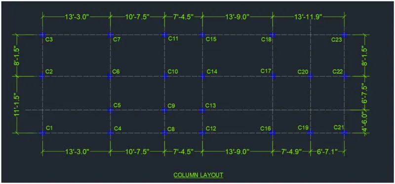
(a) Column Layout:
- STEP 1 Turn off all the layer except the column layer.
- Enter CO, Select all the columns from the building plan and copy it to a different location.
- Press Esc.
- Turn on all the layers.
- Select the Construction Line tool by entering 'XLINE command in the command tab Enter V.
- Draw lines through the mid-point of the columns.
- Enter XL in the command prompt and Click on H.
- Draw lines through the mid-point of the columns. Press Esc
- Select the Trim tool by entering TR command in the command tab.
- Press ENTER Select Edge option, and click on No Extend.
- Related Select the extruted lines
- Press Esc to cancel the TRIM command.
- Select the lines, right click, go to properties and change the line type to ACAD_ISO02W100.
- Select the Dimension tool by entering DIM in the command line.
- Select the first point and second point of the object to be measured, then drog the diamention line to the desired.
- location. Repeat for all the objects to be measured.
- Enter 'MTEXT' command in the command line.
- Specify the start point of text as required.
- Scale the text to the desired size. Copy the text box to wherever necessary.
- Enter ED in the command promt and edit the text boxes as required.
- Click Enter and press Esc.
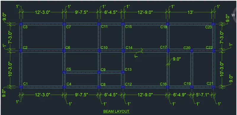
(b) Beam Layout
STEP 2
- Enter CO, Select all the column layout and copy it to a different location.
- Press Esc.
- Select the Offset tool by entering OFFSET command in the command tab
- Specify offset distance as 4.5 and Create offsets for the beam of width 9"
- Press Esc.
- Select the Offset tool by entering 'OFFSET command in the command tab.
- Specify offset distance as 6, and Create offsets for the beam of width 1
- Press Esc.
- Select the Trim tool by entering TR command in the command tab
- Select Edge option; and click on No Extend.
- Select the unwanted lines
- Press 'Esc' to cancel the TRIM command.
- Assign the bear lines to the bear layer.
- Select the Dimension tool by entering DIM in the command line
- Select the first point and second point of the object to be measured, then drag the dimension line to the desired location. Repeat for all the objects to be measured.
- Enter 'MTEXT command in the command line.
- Specify the start point of text as required.
- Copy the text box to wherever necessary.
- Enter ED in the command promt and edit the text boxes as required.
- Click Enter and press Esc.
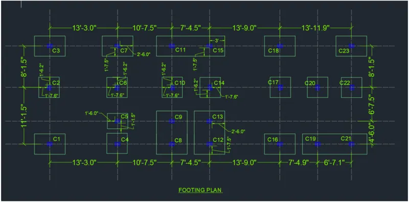
(c) Footing Plan:
STEP 3
- Enter CO. Select all the column layout and copy it to a different location.
- Press Esc.
- Select the footing layer.
- Select the Rectangle toollrom the ribbon. Draw rectangle of size @4',5".
- Enter CO, select the rectangle, specify base point as its and copy it the columns Cl, C3, C7, C16, C18, and C23.
- Press Esc.
- Select the Rectangle tool from the ribbon.
- Draw rectangle of size @4',4"
- Enter CO, select the rectangle, specify base point as its and copy it the columns C2, C6, CIO, C14, C17, C20, and C22
- Press Esc
- Select the Rectangle tool from the ribbon.
- Draw rectangle of size @4',3"
- Enter CO, select the rectangle, specify base point as its and copy it the columns C5.
- Press Esc
- Select the Rectangle tool from the ribbon.
- Draw rectangle of size @12',7.7"
- Enter CO, select the rectangle, specify base point as its and copy it the columns C11-C15 and C19-C21.
- Press Esc.
- Selec the Dimension And Text layer.
- Select the Dimension tool by entering 'DIM' in the command line.
- Select the first point and second point of the object to be measured, then drag the dimension line to the desired location. Repeat for all the objects to be measured.
- Enter 'MTEXT command in the command line.
- Specify the start point of text as required. Copy the text box to wherever necessary.
- Enter ED in the command promt and edit the text boxes as required. Click Enter and press Esc.
- Save the Drawing.
Result:-
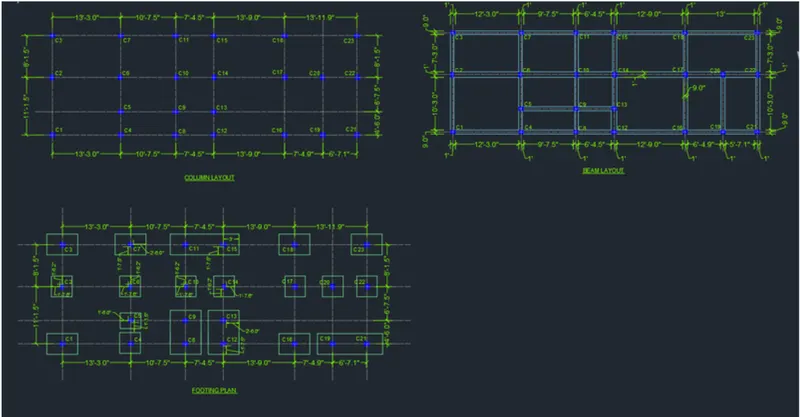
Final Risult :-