Project 1 _Creating an Architectural plan for the provided plot size and develop relevant basic structural drawings
PROJECT 1: Creating an Architectural plan for the provided plot size and develop relevant basic structural drawings
Design and Draft a layout of a residential building with the following details:
a. Plot Size: 60’x20’(18.3m x6m)
b. Orientation- Facing East
c. Develop the following: 1. Architectural Drawing (Floor Plan, Elevations, and Sections) 2. Structural Drawing (Column, Beam, Footing Plan)
AIM
To create an architectural plan for the provided plot size (18.3mx6m) with orientation facing East and develop relevant basic structural drawings such as column, beam and footing plan of a residential building.
INTRODUCTION
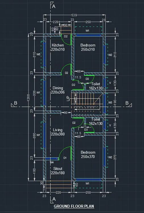
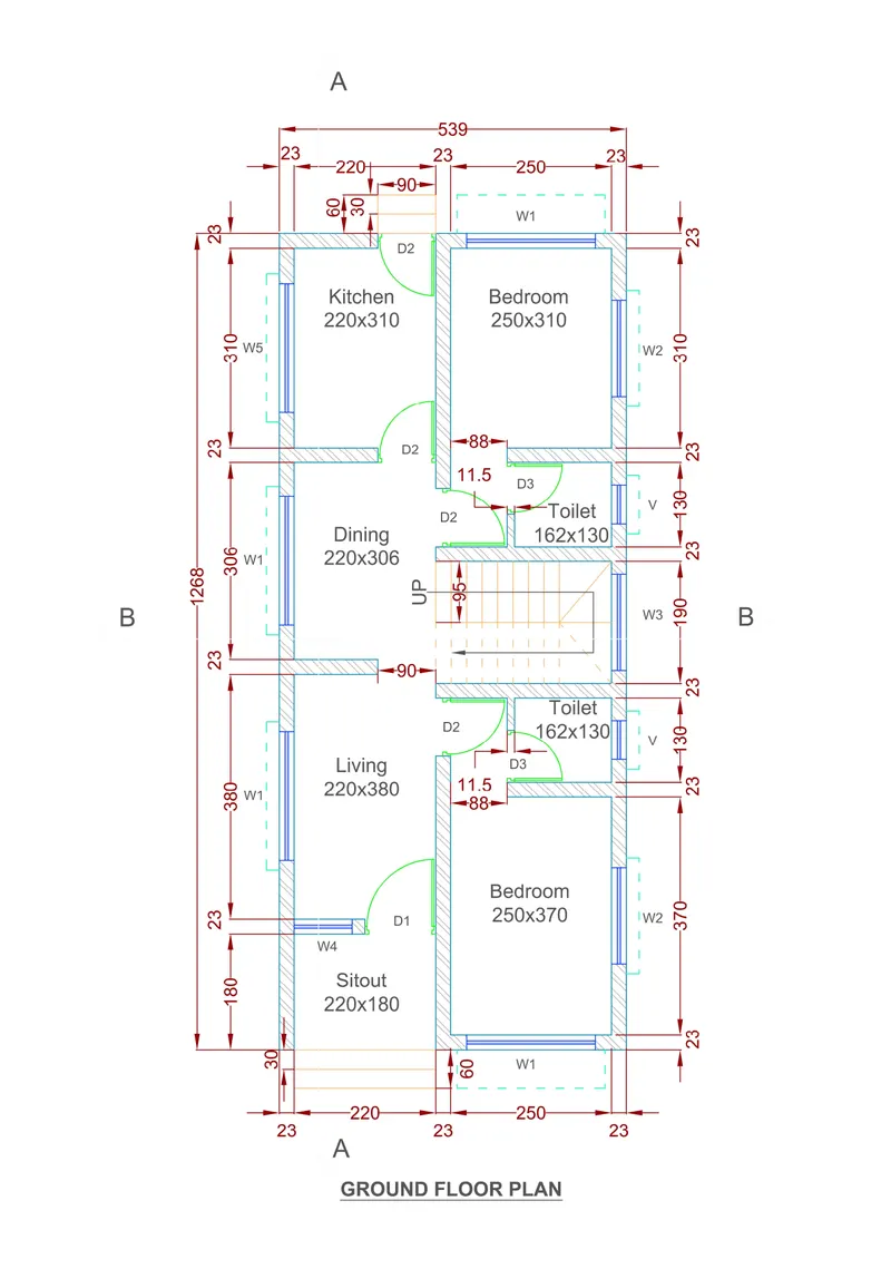
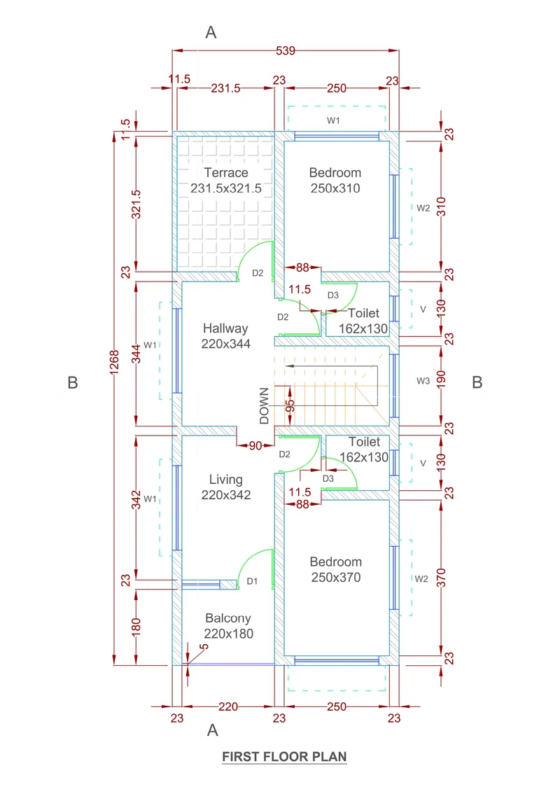
A G+1 residential building is to be drawn inside a plot of size 18.3mx6m (1830cmx600cm). The plot is facing in the East direction. The total floor size of the residential building is considered as 1268cmx539cm. The ground floor of the residential building is designed with a living room, 2 bedrooms with attached toilets,a dining, a kitchen, a staircase and a sitout. The first floor of the residential building is designed with a living room, 2 bedrooms with attached bathrooms, a hallway, a terrace, a staircase and a balcony. All dimensions are in centimeter 'cm' in this project. All the details regarding the bulding is given below.
First Floor details
Living Room: 220cmx380cm
Bedroom 1: 250cmx370cm
Bedroom 2: 250cmx310cm
Toilet 1: 162cmx130cm
Toilet 2: 162cmx130cm
Dining Room: 220cmx306cm
Kitchen: 220cmx310cm
Sitout: 220cmx180cm
Second Floor details
Living Room: 220cmx342cm
Bedroom 3: 250cmx370cm
Bedroom 4: 250cmx310cm
Toilet 3: 162cmx130cm
Toilet 4: 162cmx130cm
Balcony: 220cmx180cm
Terrace: 231.5cmx321.5cm
Wall Details
Exterior wall: 23cm
Interior wall: 11.5cm
Column, Beam, Footing and Floor slab Details
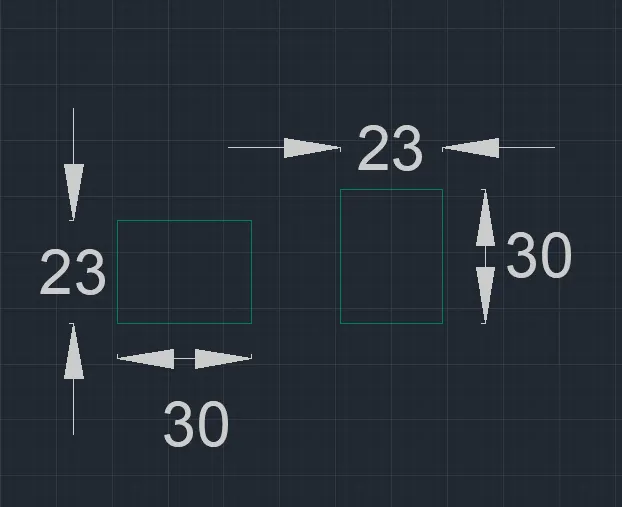
All columns are of size: 23cmx30cm or 30cmx23cm
Plinth beam: 23cmx45cm
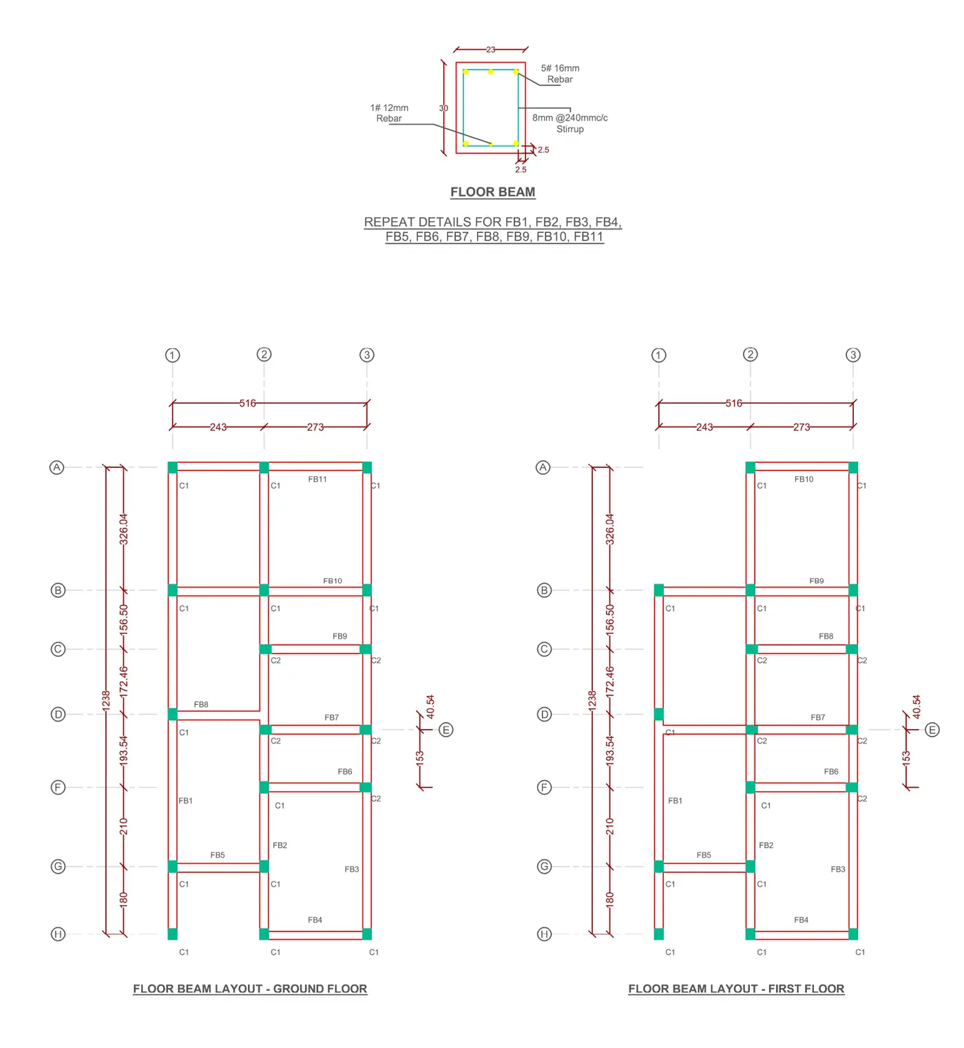
Floor Beam: 23cmx30cm
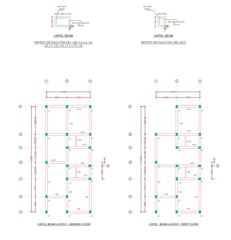
Lintel beam: 23cmx15cm
Floor slab thickness: 12.5cm
Footing: 120cmx1200cm
Door Details
D1: 110cmx210cm
D2: 90cmx210cm
D3: 80cmx210cm
Window Details
W1: 200cmx160cm
W2: 150cmx160cm
W3: 150cmx210cm
W4: 90cmx160cm
W5: 200cmx120cm
V: 60cmx60cm
Staircase
Inside stairs: 21 steps (Tread: 24, Riser: 14.88)
Ouside stairs: 3 steps (Tread: 30, Riser: 15)
PROCEDURE
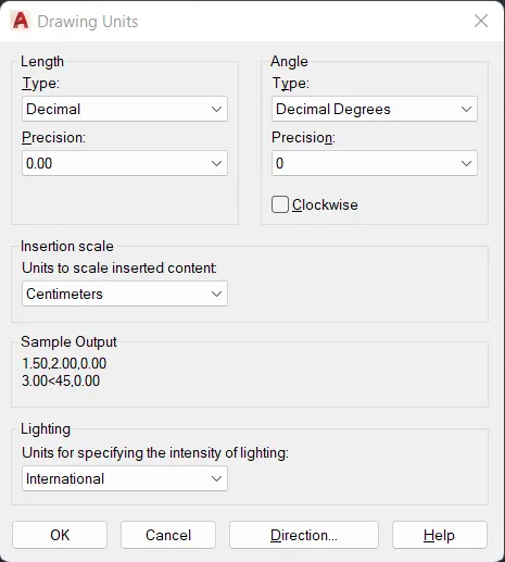
Open the AutoCAD Application and create a new AutoCAD file with imperial settings. Set the length type in 'Decimal' and precision (0.00), insertion scale to 'Centimeters' in the Drawing Units and press OK.
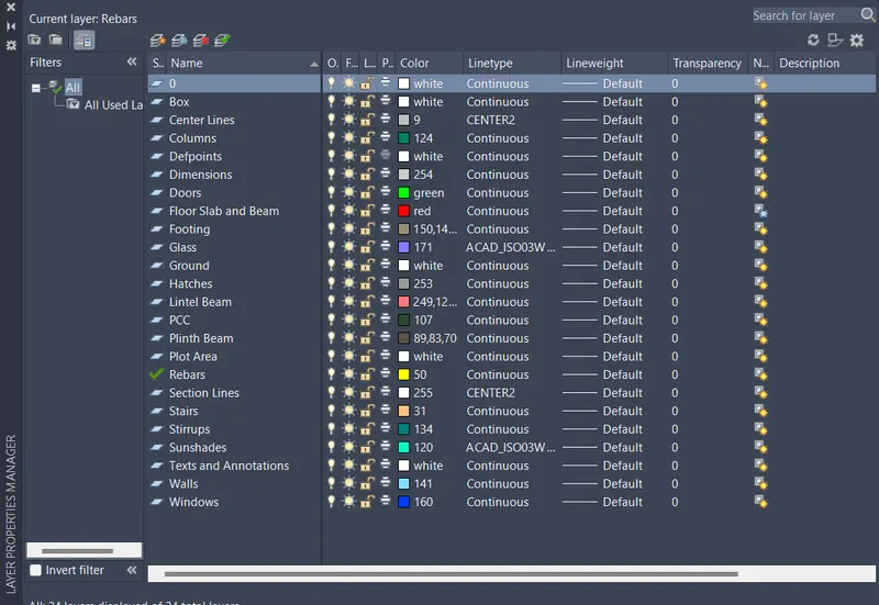
Layers are created, the different layers used in this project is shown below
Part A: Architectural Drawings
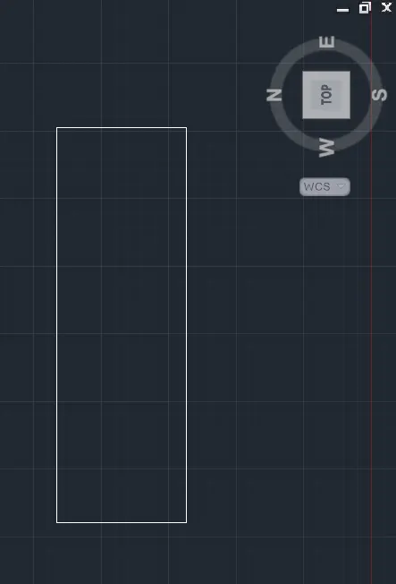
1. Draw the plot
- Type 'LA' in the command line and enter to get layers
- Create a new layer 'Plot Area'
- Type 'REC' in the command line and enter to get rectangle
- Create a rectangle of size 1830cmx600cm
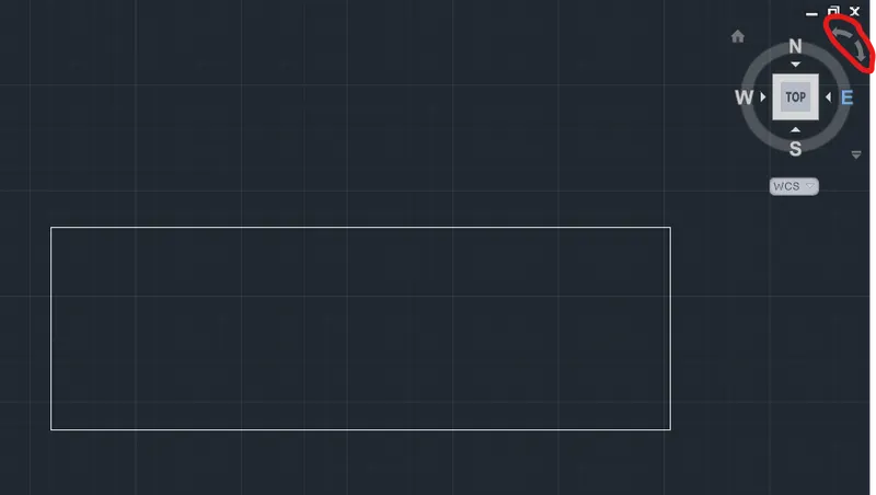
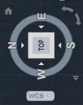
- Set the orientation in East direction
- Using the marked arrows, change the orientation to East direction
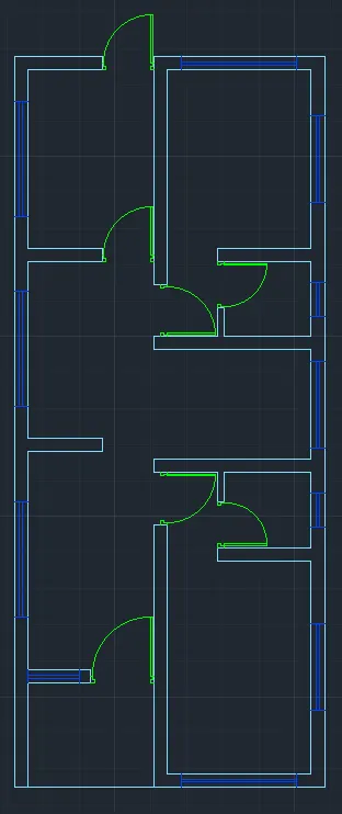
2. Draw the ground floor plan
a) Draw the outline
- Type 'LA' in the command line and enter to get layers
- Create a new layer "Wall"
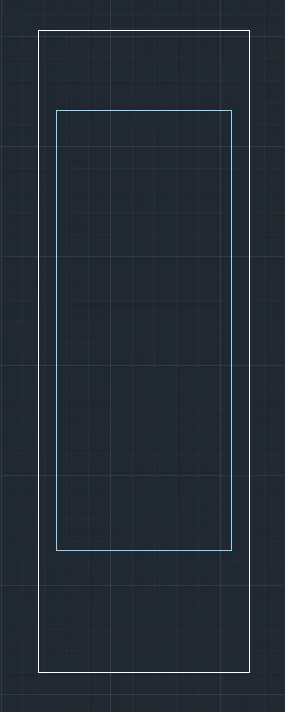
- Type 'REC' in the command line and enter to get rectangle
- Create a rectangle of size 1268cmx539cm
- Type 'MO' in the command line and enter to get move tool
- Select the rectangle and move inside the plot area
b) Draw the walls
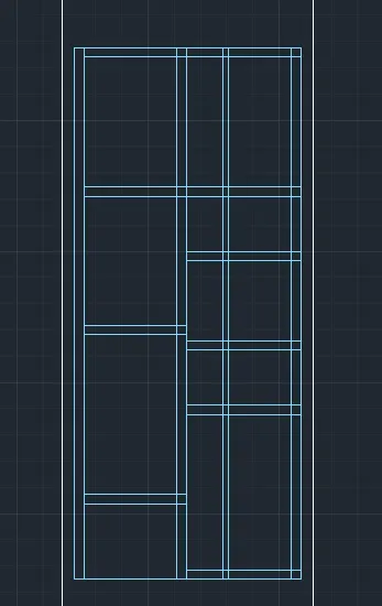
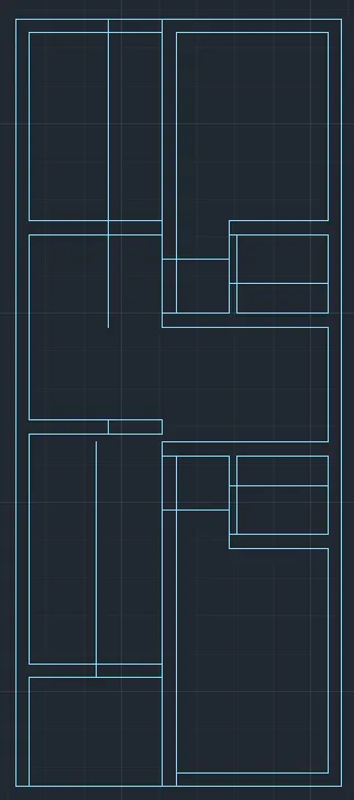
- Select the outline (rectangle) and then type 'EXPLODE' and enter for offseting each lines
- Type 'OFF' in the command line and enter to get offset tool
- Offset all necessary lines to draw the plan
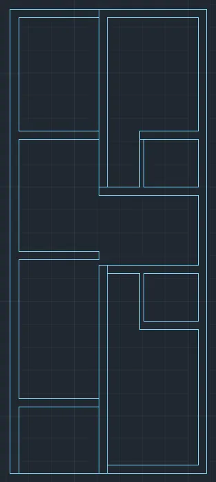
- Type 'TR' in the command line and enter to get trim tool
- Trim all unnecessary lines
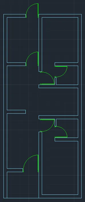
c) Draw the hallways and doors
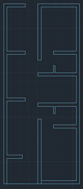
- Type 'OFF' in the command line and enter to get offset tool
- Offset all necessary lines to draw the plan
- Type 'TR' in the command line and enter to get trim tool
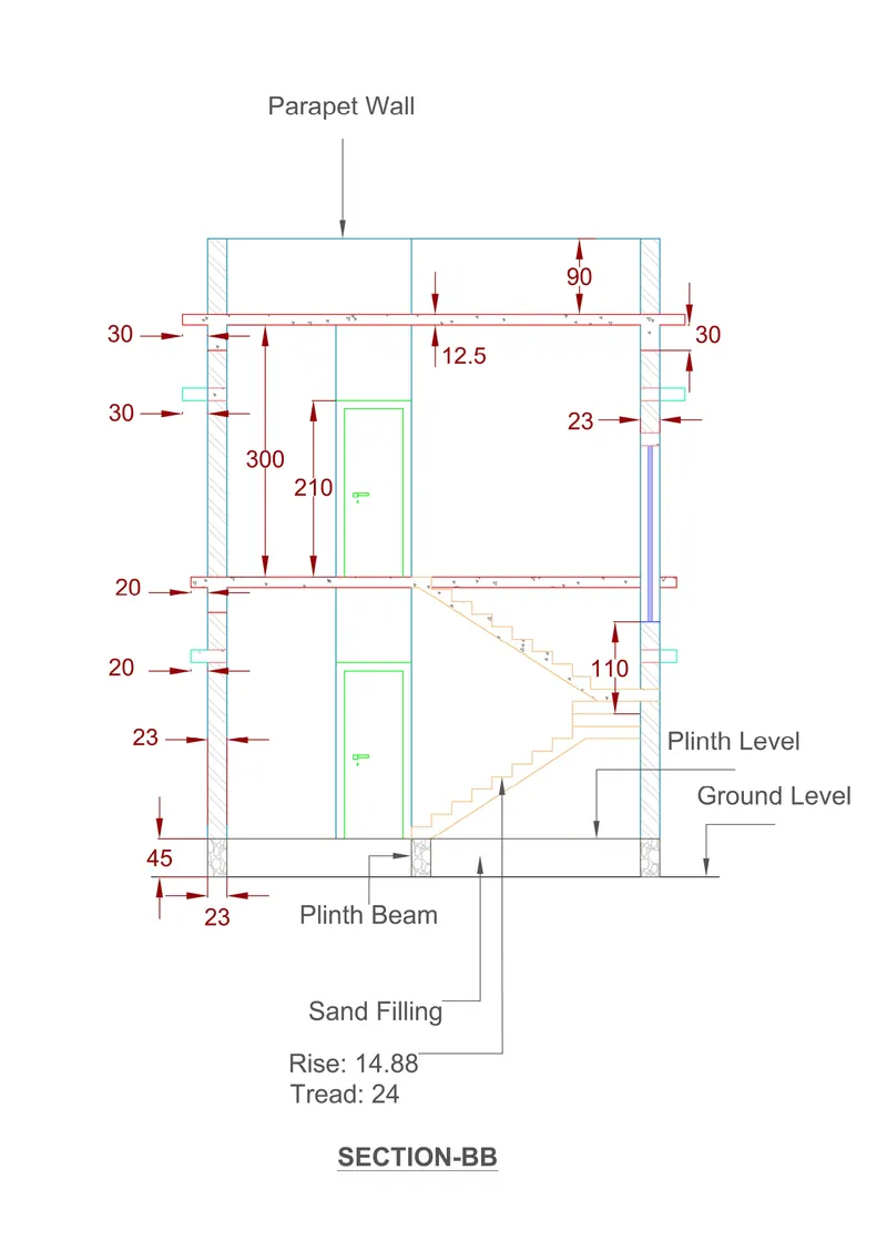
- Trim all unnecessary lines
- Type 'LA' in the command line and enter to get layers
- Create a new layer "Doors"
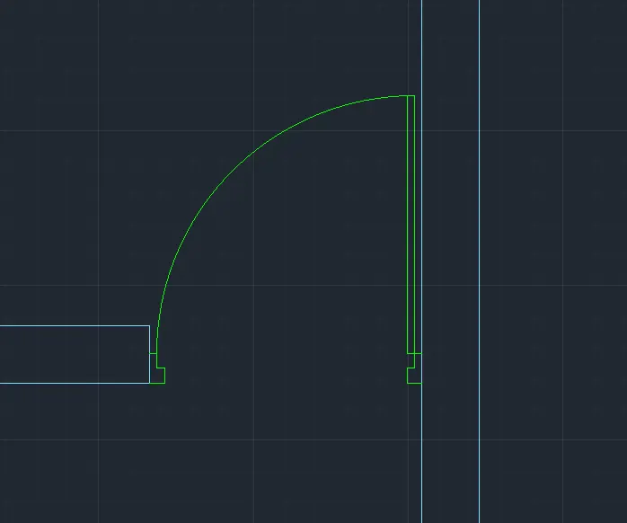
- Draw door D1
- Type 'L' in the command line and enter to get line
- Draw line from opening, 6cm in the x direction, then 6cm in the y direction, then 3cm in the -x direction, then 6cm in the y direction and then 3cm in the -x direction
- Type 'MI' in the command line and enter to get mirror tool
- Select all the lines drawn and enter, then specify the first point (midpoint of the door) and second point of the mirror.
- Type 'L' in the command line and enter to get line
- Draw line 104cm in the y direction from the drawn line, then 3cm in the -x direction and then 104cm in the -y direction.
- Type 'C' in the command line and enter to get circle
- Draw a circle from one end of the line to the other
- Type 'TR' in the command line and enter to get trim tool
- Trim all unnecessary lines and arcs
- Type 'L' in the command line and enter to get line
- Draw door D2
- Type 'L' in the command line and enter to get line
- Draw line from opening, 6cm in the x direction, then 6cm in the y direction, then 3cm in the -x direction, then 6cm in the y direction and then 3cm in the -x direction
- Type 'MI' in the command line and enter to get mirror tool
- Select all the lines drawn and enter, then specify the first (midpoint of the door) and second point of the mirror.
- Type 'L' in the command line and enter to get line
- Draw line 84cm in the y direction from the drawn line, then 3cm in the -x direction and then 84cm in the -y direction.
- Type 'C' in the command line and enter to get circle
- Draw a circle from one end of the line to the other
- Type 'TR' in the command line and enter to get trim tool
- Trim all unnecessary lines and arcs
- Type 'CO' in the command line and enter to get copy tool
- Select all the door components and paste it according to the design
- Type 'RO' in the command line and enter to get rotate tool
- Select all the door components and rotate it according to the design
- Type 'L' in the command line and enter to get line
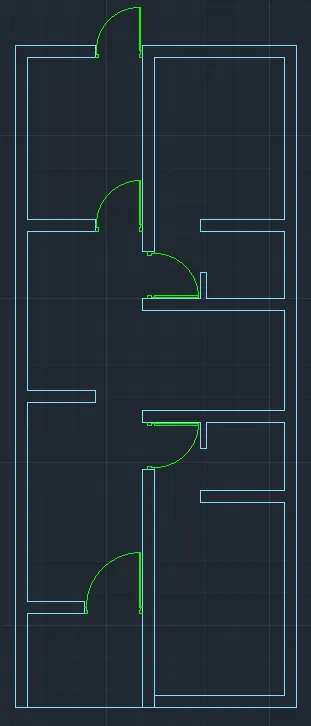
- Draw door D3
- Type 'L' in the command line and enter to get line
- Draw line from opening, 6cm in the x direction, then 5.5cm in the y direction, then 3cm in the -x direction, then 6cm in the y direction and then 3cm in the -x direction
- Type 'MI' in the command line and enter to get mirror tool
- Select all the lines drawn and enter, then specify the first (midpoint of the door) and second point of the mirror.
- Type 'L' in the command line and enter to get line
- Draw line 74cm in the y direction from the drawn line, then 3cm in the -x direction and then 74cm in the -y direction.
- Type 'C' in the command line and enter to get circle
- Draw a circle from one end of the line to the other
- Type 'TR' in the command line and enter to get trim tool
- Trim all unnecessary lines and arcs
- Type 'CO' in the command line and enter to get copy tool
- Select all the door components and paste it according to the design
- Type 'RO' in the command line and enter to get rotate tool
- Select all the door components and rotate it according to the design
- Type 'L' in the command line and enter to get line
d) Draw windows
- Type 'LA' in the command line and enter to get layers
- Create a new layer "Windows"
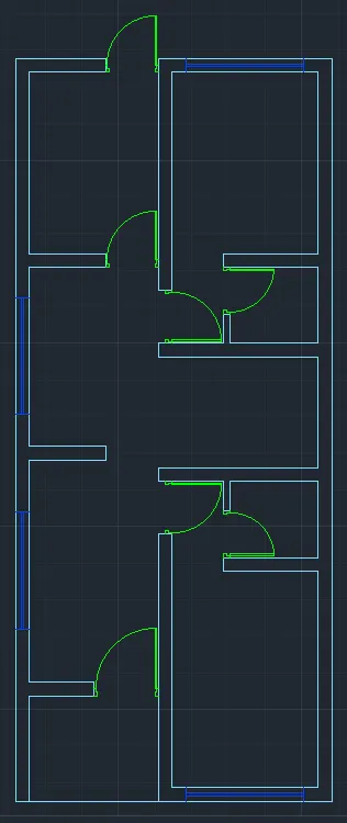
- Draw window W1
- Type 'L' in the command line and enter to get line
- Draw a line of 23cm in x direction, then 200cm in y direction from the midpoint of the previous line
- Type 'OFF' in the command line and enter to get offset tool
- Offset all essential lines to obtain the window
- Type 'TR' in the command line and enter to get trim tool
- Trim all unnecessary lines
- Type 'CO' in the command line and enter to get copy tool
- Select the window (W1) and paste it in the place according to the design
- Type 'RO' in the command line and enter to get rotate tool
- Select the window (W1) and rotate it according to the design
- Type 'L' in the command line and enter to get line
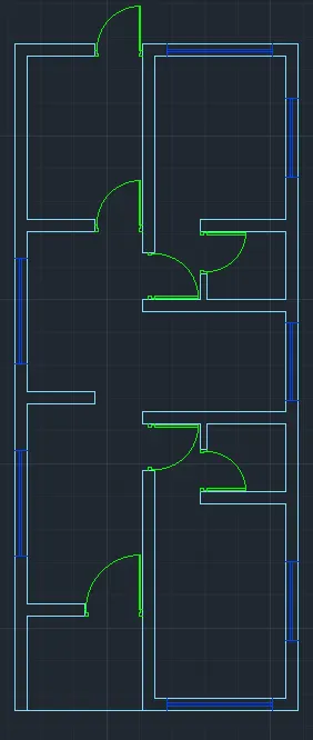
- Draw window W2
- Type 'L' in the command line and enter to get line
- Draw a line of 23cm in x direction, then 150cm in y direction from the midpoint of the previous line
- Type 'OFF' in the command line and enter to get offset tool
- Offset all essential lines to obtain the window
- Type 'TR' in the command line and enter to get trim tool
- Trim all unnecessary lines
- Type 'CO in the command line and enter to get copy tool
- Select the window (W2) and paste it in the place according to the design
- Type 'RO' in the command line and enter to get rotate tool
- Select the window (W2) and rotate it according to the design
- Type 'L' in the command line and enter to get line
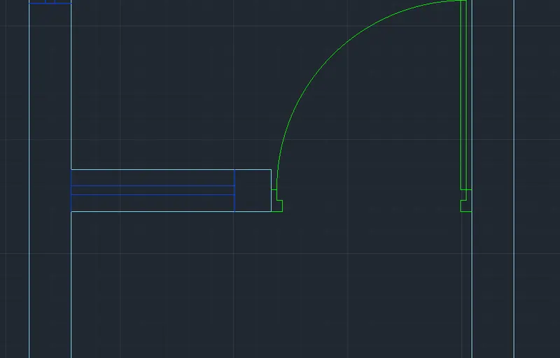
- Draw window W3
- Type 'L' in the command line and enter to get line
- Draw a line of 23cm in y direction, then 90cm in x direction from the midpoint of the previous line
- Type 'OFF' in the command line and enter to get offset tool
- Offset all essential lines to obtain the window
- Type 'TR' in the command line and enter to get trim tool
- Trim all unnecessary lines
- Type 'L' in the command line and enter to get line
- Draw window W4
- Type 'L' in the command line and enter to get line
- Draw a line of 23cm in y direction, then 200cm in x direction from the midpoint of the previous line
- Type 'OFF' in the command line and enter to get offset tool
- Offset all essential lines to obtain the window
- Type 'TR' in the command line and enter to get trim tool
- Trim all unnecessary lines
- Type 'L' in the command line and enter to get line
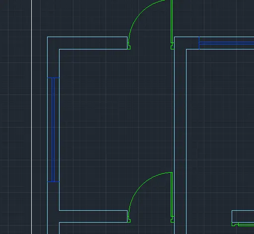
- Draw ventilation V
- Type 'L' in the command line and enter to get line
- Draw a line of 23cm in y direction, then 60cm in x direction from the midpoint of the previous line
- Type 'OFF' in the command line and enter to get offset tool
- Offset all essential lines to obtain the window
- Type 'TR' in the command line and enter to get trim tool
- Trim all unnecessary lines
- Type 'CO' in the command line and enter to get copy tool
- Select all the door components and paste it according to the design
- Type 'L' in the command line and enter to get line
e) Draw stairs
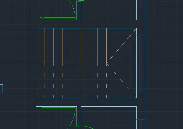
- Type 'LA' in the command line and enter to get layers
- Create a new layer "Stairs"
- Type 'L' in the command line and enter to get line
- Draw a line from one end to another end
- Type 'OFF' in the command line and enter to get offset tool
- Offset 95cm from a line to obtain stair rail
- Offset 24cm from the line drawn for 8 times
- Type 'L' in the command line and enter to get line
- Draw a line from the corner to another corner
- Type 'MI' in the command line and enter to get mirror tool
- Select the drawn line and mirror it
- Select all the second flight steps and give linetype 'ACAD_ISO03W100'
f) Draw sunshades
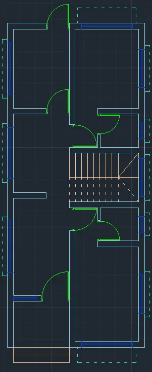
- Type 'LA' in the command line and enter to get layers
- Create a new layer "Sunshades" with linetype 'ACAD_ISO03W100'
- Type 'L' in the command line and enter to get line
- Draw 20cm projections of sunshade 15cm from both sides of window for all the windows except W1 windows of bedrooms
- Draw 60cm projections of sunshade 15cm from both sides of window for W1 windows of bedrooms
g) Insert dimensions in the plan
- Type 'LA' in the command line and enter to get layer properties
- Create a new layer "Dimensions"
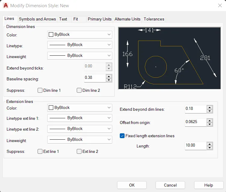
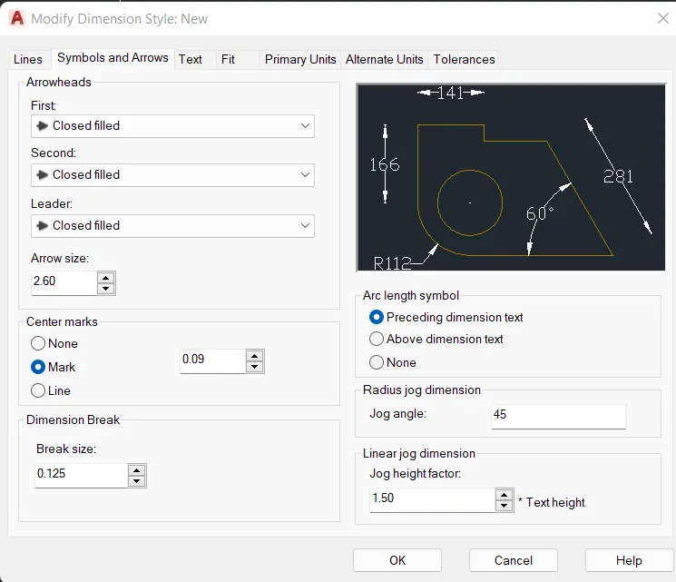
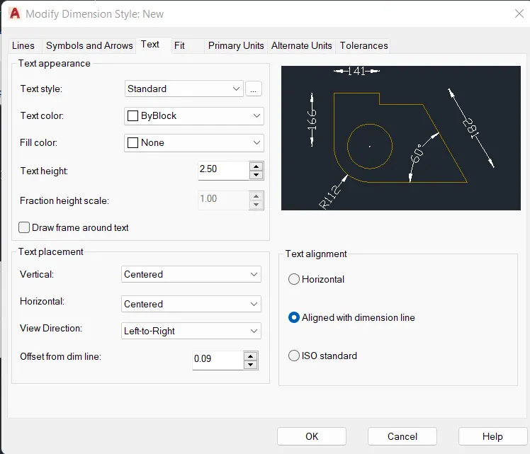
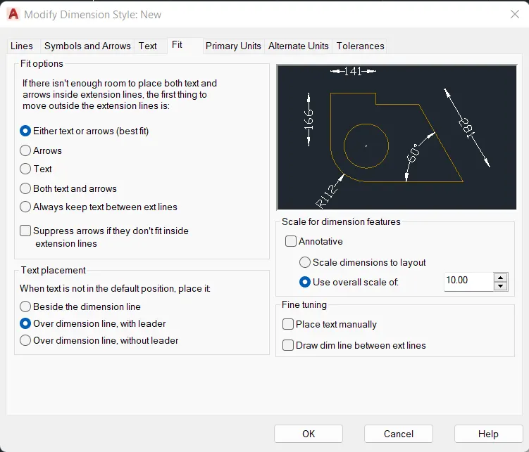
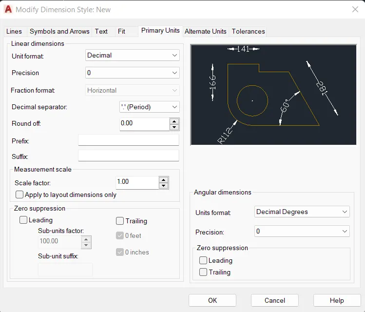
- Type 'DIMSTY' in the command line and enter to get dimension style settings
- Dimension Style is created as New, the settings are shown below
- In Lines, Fixed length extension lines is given as 10cm.
- In Symbols and Arrows, Arrow size is given as 2.60cm.
- In Text, Text height is given as 2.50cm
- In Fit, Overall scale is given as 10
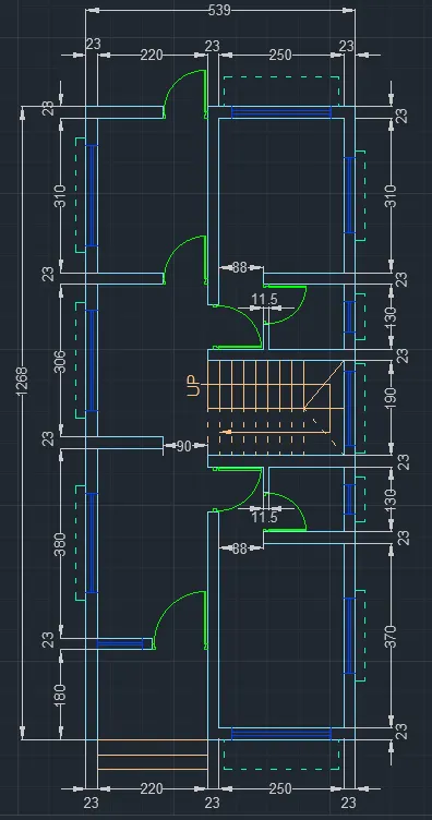
- Turn off the "Plot Area" layer
- Type 'DIM' in the command line and enter to get dimension line
- Mark all necessary dimensions
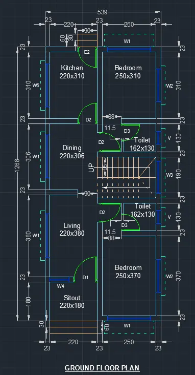
h) Insert text and annotations
- Type 'LA' in the command line and enter to get layer properties
- Create a new layer "Texts and Annotations"
- Type 'MTEXT' in the command line and enter to get multi line text
- Type text wherever required as per the plan
- Different fonts are used
- Type 'MLD' in the command line and enter to get multi leader tool
- Draw a multileader to represent the stair direction
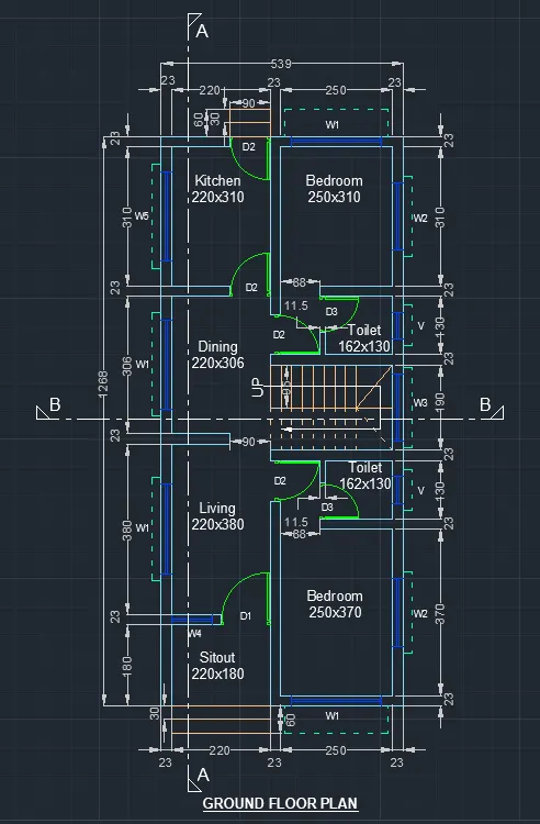
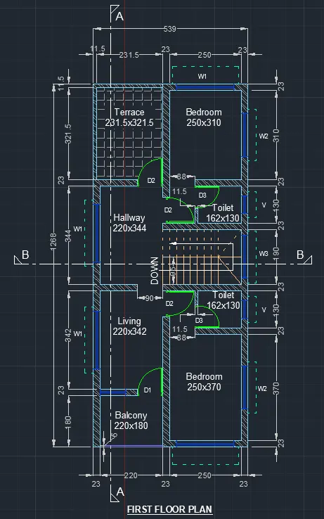
i) Insert section lines
- Type 'LA' in the command line and enter to get layer properties
- Create a new layer "Section Lines" with line type 'CENTER 2'
- Type 'L' in the command line and enter to get line tool
- Draw lines according to the given figure to indicate section lines
- Draw triangles at the end of the section lines
- Type 'TEXT' in the command line and enter to get single line text
- Type the section names, 'COPY', 'MTEDIT' tools are used
j) Hatching
- Type 'LA' in the command line and enter to get layer properties
- Create a new layer "Hatches"
- Type 'H' in the command line and enter to get hatch creation
- Pick internal point: Point all the walls (Pattern: ANSI32)
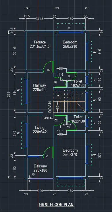
3. Draw the first floor plan
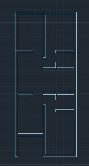
Since the ground floor and first floor has almost same features and sizes, the copy of the ground floor plan is taken as the reference for the first floor plan.
a) Draw the outline
- Type 'CO' in the command line and enter to get copy tool
- Select the ground floor plan and paste it somewhere
- Only turn on "Walls" layer and all other layers should be turned off
- Type 'MO' in the command line and enter to get move tool
- Select some walls and move according to the desired design
- Type 'EX' in the command line and enter to get extend tool
- Select the lines to extend
- Type 'TR' in the command line and enter to get trim tool
- Trim all unnecessary parts, that need not to be in the first floor plan
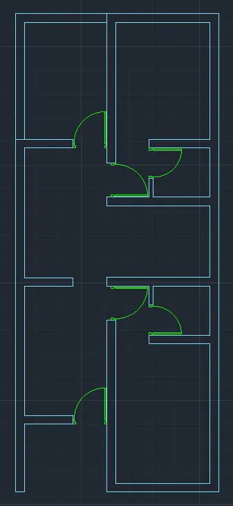
b) Draw the doors
- Turn on the "Doors" layer
- Type 'E' in the command line and enter to get erase tool
- Select the unnecessary doors
- Type 'CO' in the command line and enter to get copy tool
- Select the door (D2) and place it for entering balcony
- Type 'L' in the command line and enter to get line
- Draw lines to create a door openings
- Type 'TR' in the command line and enter to get trim tool
- Remove all unnecessary lines
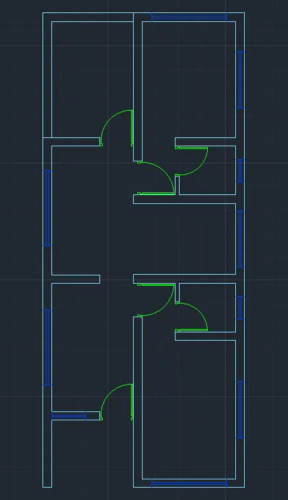
c) Draw the windows
- Turn on the "Windows" layer
- Type 'E' in the command line and enter to get erase tool
- Select the unnecessary windows
- Type 'MO' in the command line and enter to get move tool
- Select some windows and align them in the middle of the walls
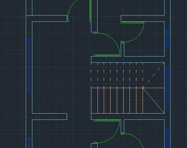
d) Draw the stairs
- Turn on "Stairs" layer
- Type 'E' in the command line and enter to get erase tool
- Select the unnecessary stairs
- Type 'MI' in the command line and enter to get mirror tool
- Select the stairs and mirror it
e) Draw the sunshades
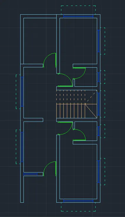
- Turn on "Sunshades" layer
- Type 'E' in the command line and enter to get erase tool
- Select the unnecessary sunshades
- Type 'MO' in the command line and enter to get move tool
- Select some sunshades and align them with the windows
- Select all the sunshades except W1 windows of bedrooms and extend 10cm
- Type 'F' in the command line and enter to get fillet tool
- Fillet all the sunshades
f) Draw the terrace and balcony glass rail
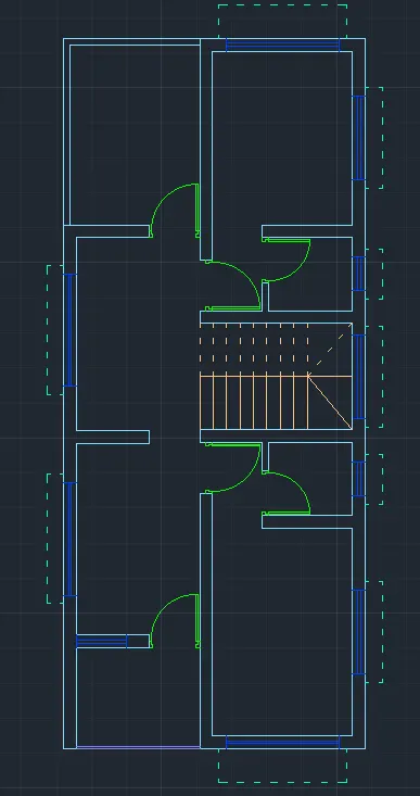
- Select "Walls" as current layer
- Type 'OFF' in the command line and enter to get offset tool
- Offset 11.5cm from both adjacent lines
- Type 'TR' in the command line and enter to get trim tool
- Remove all unnecessary lines
- Type 'LA' in the command line and enter to get layer properties
- Create a new layer "Glass"
- Type 'L' in the command line and enter to get line
- Draw a line from one end to other in the balcony
- Type 'OFF' in the command line and enter to get offset tool
- Offset 5cm from the line drawn
g) Insert dimensions in the plan
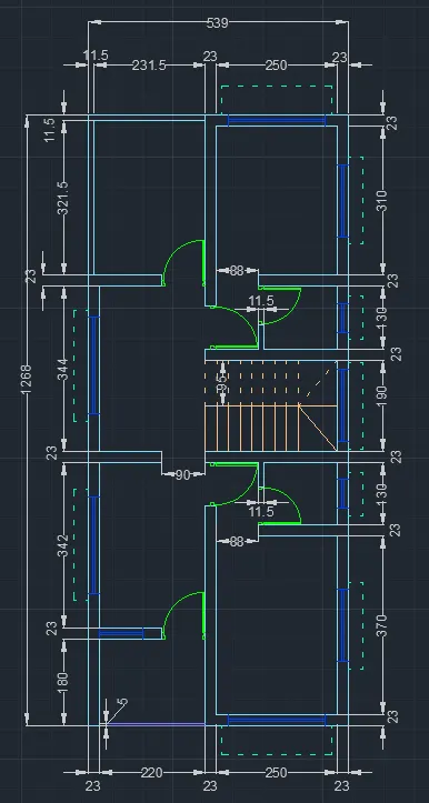
- Turn on "Dimensions" layer
- Dimension style is same as given above
- Change the dimensions for terrace, hallway, living room
- Add dimensions to glass rail of the balcony
h) Insert text and annotations
- Turn on "Texts and Annotations" layer
- Type 'MTEDIT' in the command line and enter to get multiline text edit tool
- Edit all the required texts as per the desired plan
i) Insert section lines
- Turn on "Section Lines" layer
j) Hatching
- Turn on "Hatches" layer
- Type 'E' in the command line and enter to get erase tool
- Select the all hatches in the first floor plan
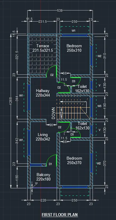
- Type 'H' in the command line and enter to get hatch creation
- Pick internal point: Point all the walls (Pattern: ANSI32)
- Pick internal point: Point the terrace portion (Pattern: ANGLE)
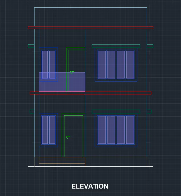
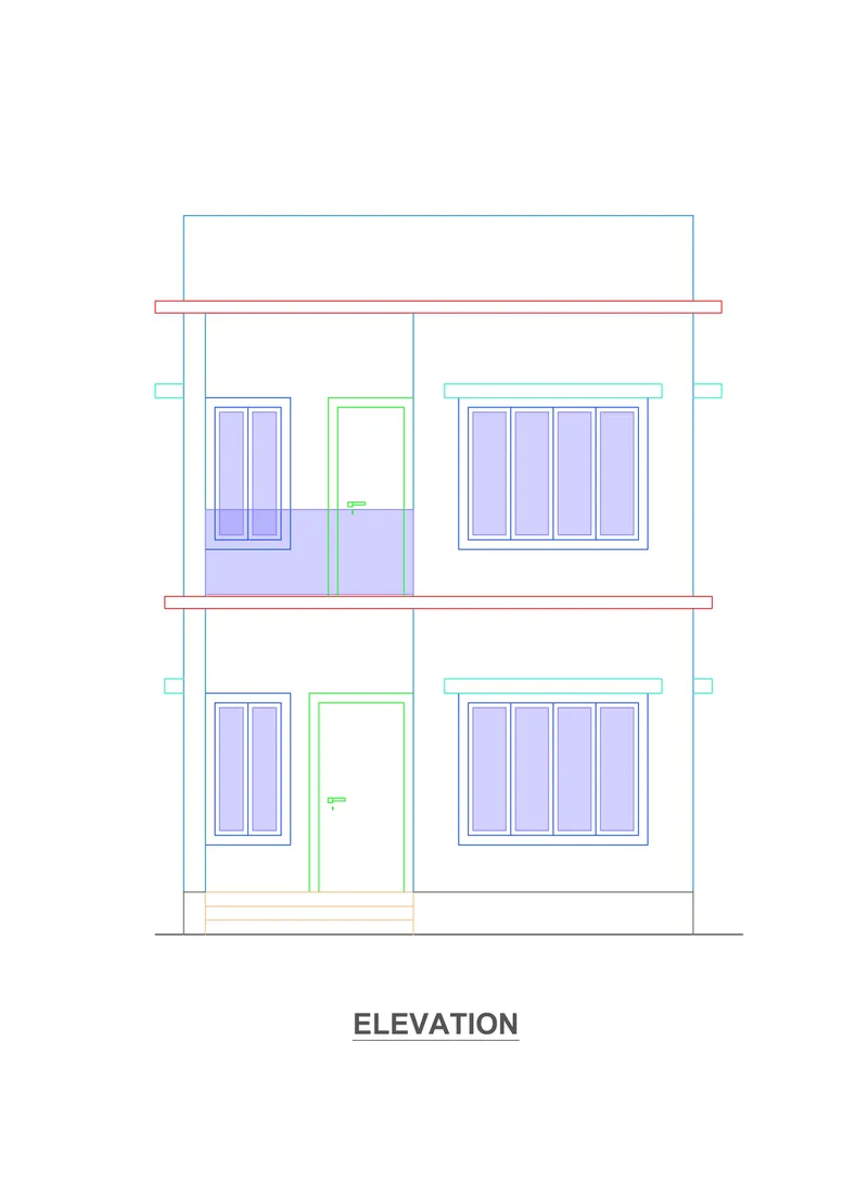
4. Draw the elevation of the residential building
a) Draw the outline of the ground floor elevation
- Turn off "Dimensions", "Texts and Annotations", "Hatches", and "Section Lines" layers
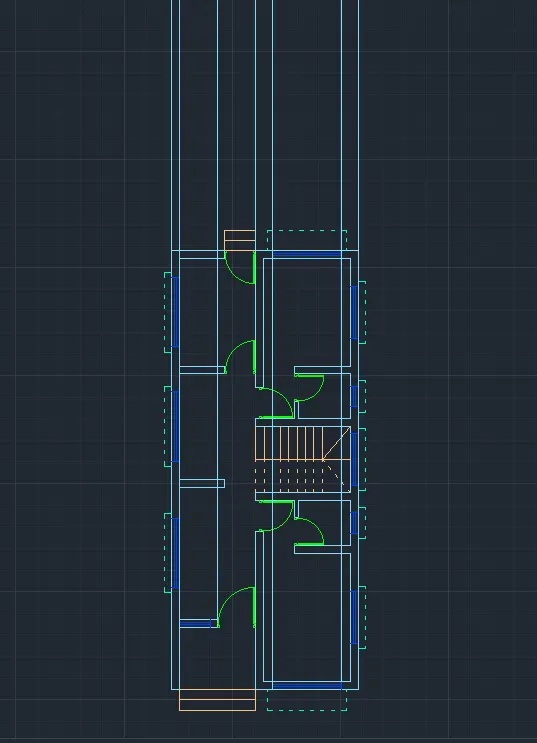
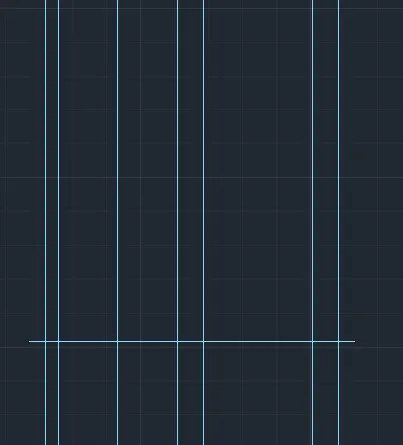
- Type 'RAY' in the command line and enter to get ray tool
- Draw rays from the ground floor plan
- Type 'L' in the command line and enter to get line
- Draw a line horizontally for the base
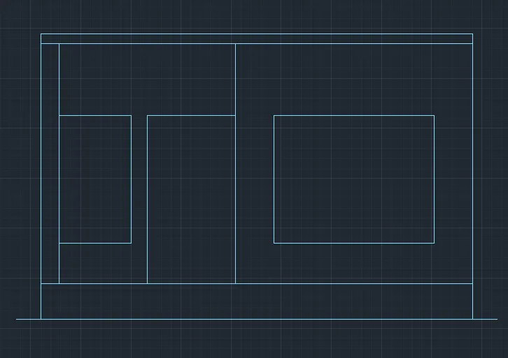
- Type 'OFF' in the command line and enter to get offset tool
- Offset 45cm from the line drawn for plinth beam
- Offset 210cm from the new line for door level
- Offset 160cm from the new line for window sill level
- Offset 300cm from the line drawn for floor level
- Offset 12.5cm from the previous line for slab thickness
- Type 'TR' in the command line and enter to get trim tool
- Remove all unnecessary lines
b) Draw the sunshades
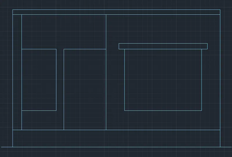
- Type 'REC' in the command line and enter to get rectangle
- Type 'TRA' in command line to get tracking point
- Select the first tracking point as the corner of the window
- Move the cursor in -x direction, type '15cm' and enter, again press enter to get rectangle
- Draw a rectangle of 230cmx15cm from that point in the x direction
- Type 'TRA' in command line to get tracking point
- Type 'XL' in the command line and enter to get xline tool
- Draw horizontal line from sunshade
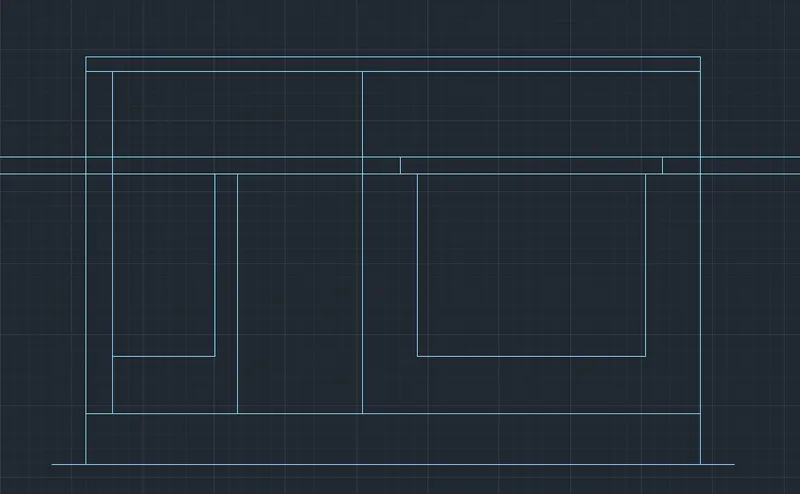
- Type 'OFF' in the command line and enter to get offset tool
- Offset 20cm from the wall on both sides
- Type 'TR' in the command line and enter to get trim tool
- Remove all unnecessary lines
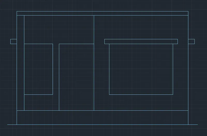
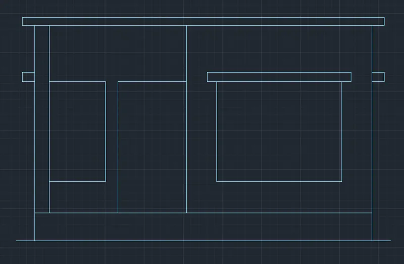
c) Draw floor slab
- Type 'OFF' in the command line and enter to get offset tool
- Offset 20cm from the slab on both sides
- Type 'EX' in the command line and enter to get extend tool
- Select the lines to extend
- Type 'TR' in the command line and enter to get trim tool
- Remove all unnecessary lines
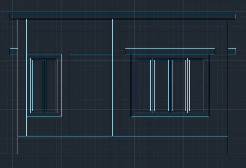
d) Draw the window interior
- Type 'OFF' in the command line and enter to get offset tool
- Offset all necessary lines
- Type 'TR' in the command line and enter to get trim tool
- Remove all unnecessary lines
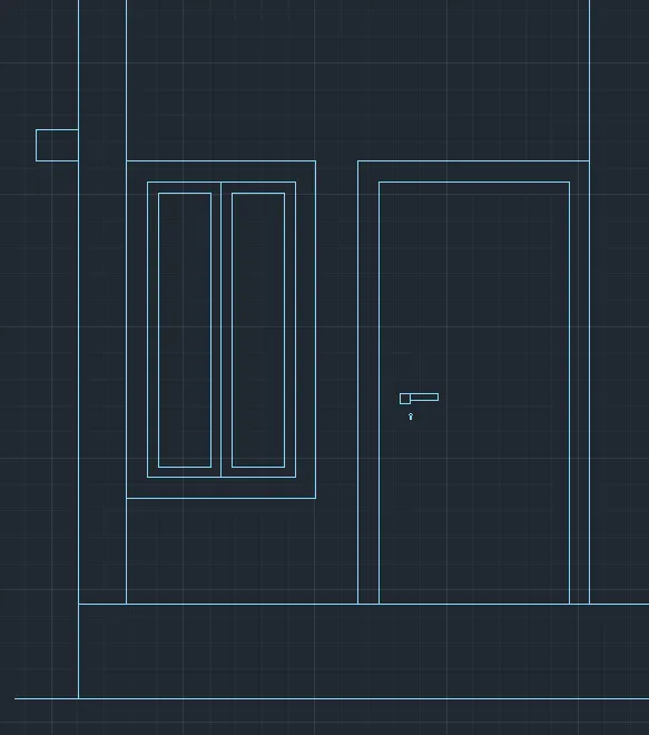
e) Draw door frame and door interior
- Type 'OFF' in the command line and enter to get offset tool
- Offset all necessary lines to draw door frame
- Type 'REC' in the command line and enter to get rectangle
- Draw door knob using rectangle and keyhole
- Type 'C' in the command line and enter to get circle
- Draw the keyhole completely
- Type 'TR' in the command line and enter to get trim tool
- Remove all unnecessary lines
f) Draw the entrance steps
- Type 'OFF' in the command line and enter to get offset tool
- Offset all necessary lines to draw steps
- Type 'TR' in the command line and enter to get trim tool
- Remove all unnecessary lines
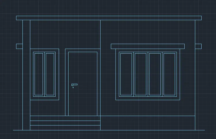
g) Give layer properties to each segments
- Turn on all layers
- Select door, and its parts and click the "Doors" layer in the layer tab
- Select windows and its parts and click the "Windows" layer in the layer tab
- Select glass panel and click the "Glass" layer in the layer tab
- Select sunshades and click the "Sunshades" layer in the layer tab
- Select steps and click the "Stairs" layer in the layer tab
- Type 'LA' in the command line and enter to get layers
- Create a new layer "Plinth beam"
- Select the plinth beam drawn
- Type 'LA' in the command line and enter to get layers
- Create a new layer "Floor slab"
- Select the floor slab drawn
- Type 'LA' in the command line and enter to get layers
- Create a new layer "Ground level"
- Select the ground drawn
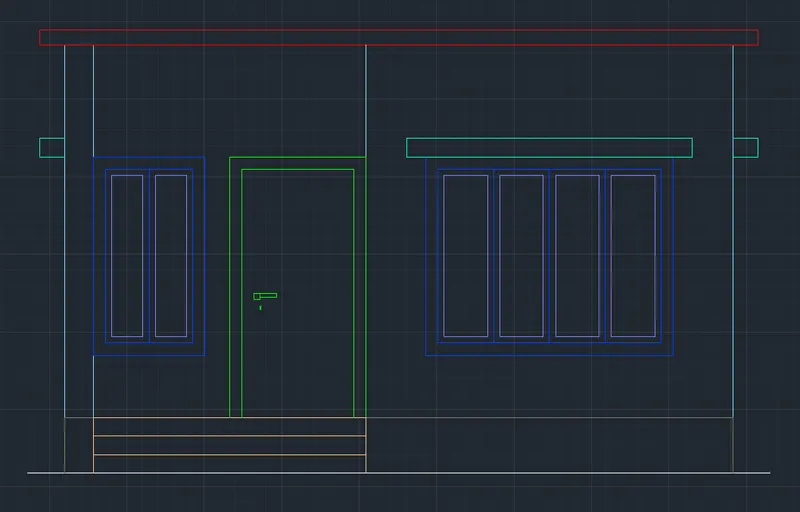
h) Draw the first floor outline
- Type 'CO' in the command line and enter to get copy tool
- Select the ground floor and paste it upper the ground floor
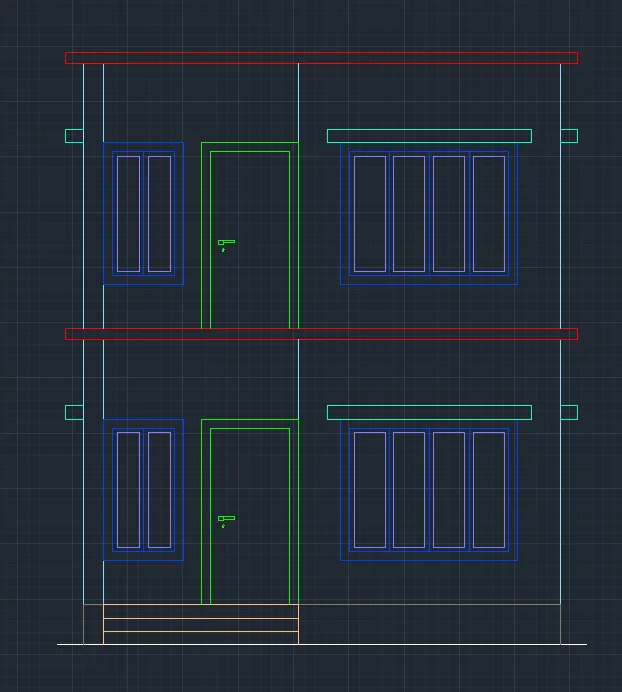
i) Extend the sunshades
- Type 'OFF' in the command line and enter to get offset tool
- Offset 10cm from the slab on both sides
- Type 'EX' in the command line and enter to get extend tool
- Select the lines to extend
- Type 'TR' in the command line and enter to get trim tool
- Remove all unnecessary lines
j) Extend floor slab
- Type 'OFF' in the command line and enter to get offset tool
- Offset 10cm from the slab on both sides
- Type 'EX' in the command line and enter to get extend tool
- Select the lines to extend
- Type 'TR' in the command line and enter to get trim tool
- Remove all unnecessary lines
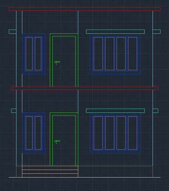
k) Redraw the door in the balcony
- Type 'E' in the command line and enter to get erase tool
- Remove the door frame
- Type 'OFF' in the command line and enter to get offset tool
- Offset 20cm from the outer side
- Offset all essential lines to get the door frame
- Type 'TR' in the command line and enter to get trim tool
- Remove all unnecessary lines
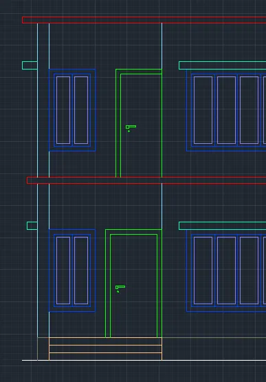
l) Draw the glass rail in the balcony
- Select "Glass" Layer
- Type 'REC' in the command line and enter to get rectangle
- Draw a rectangle of 210cmx90cm with 2cm offset from the floor slab
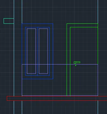
m) Draw the parapet wall
- Type 'REC' in the command line and enter to get rectangle
- Draw a rectangle of 539cmx90cm from the floor slab
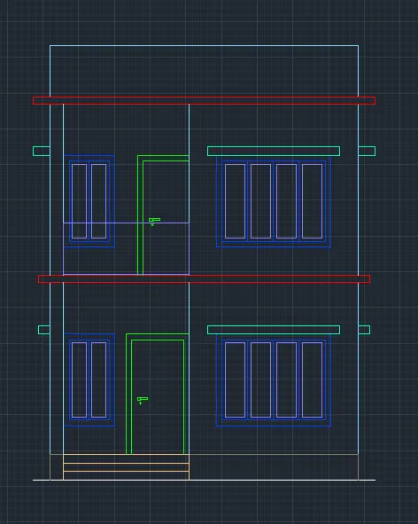
n) Hatching
- Select "Hatch" layer
- Type 'H' in the command line and enter to get hatch creation
- Pick internal point: Pick all the glasses (Pattern: SOLID, Colour: 171, Transparency: 64)
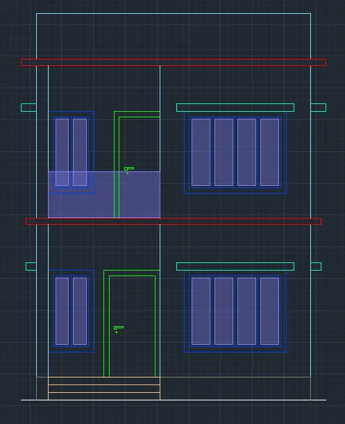
o) Insert text
- Select "Texts and Annotations" layer
- Type 'MTEXT' in the command line and enter to get multi line text
- Type text wherever required
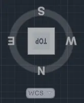
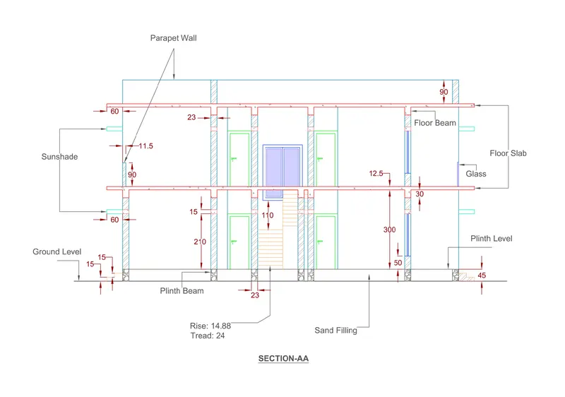
5. Draw the section-AA
Rotated the drawing as shown below to draw section-AA
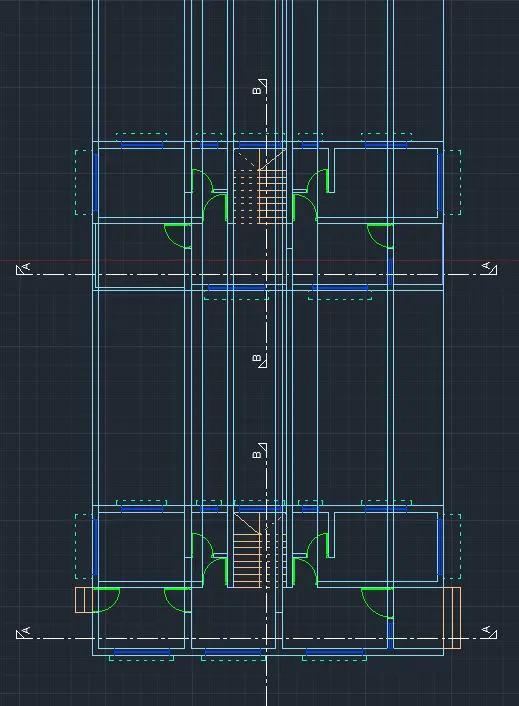
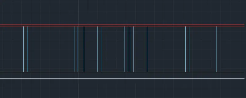
a) Draw the ground floor outline
- Turn off "Dimensions", "Texts and Annotations", and "Hatches" layers
- Select "Wall" layer
- Type 'RAY' in the command line and enter to get ray tool
- Draw rays of wall from the ground floor plan
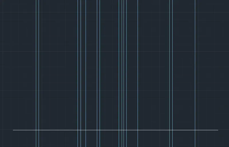
- Type 'L' in the command line and enter to get line
- Draw a line horizontally for the base
- Type 'OFF' in the command line and enter to get offset tool
- Offset 45cm from the line drawn for plinth beam
- Offset 300cm from the line drawn for floor level
- Offset 12.5cm from the previous line for slab thickness
- Type 'TR' in the command line and enter to get trim tool
- Remove all unnecessary lines
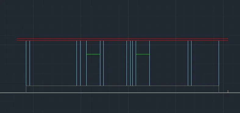
b) Draw the door
- Type 'OFF' in the command line and enter to get offset tool
- Offset 210cm from the plinth level
- Type 'TR' in the command line and enter to get trim tool
- Remove all unnecessary lines
- Select door and click the "Doors" layer in the layer tab
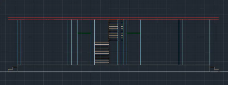
c) Draw the stairs
- Type 'RAY' in the command line and enter to get ray tool
- Draw rays of window from the ground floor plan
- Type 'OFF' in the command line and enter to get offset tool
- Offset 14.88cm from the plinth level to desired length
- Type 'TR' in the command line and enter to get trim tool
- Remove all unnecessary lines
- Select stairs and click the "Stairs" layer in the layer tab
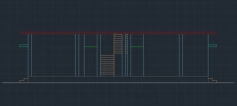
d) Draw the sunshades
- Type 'XL' in the command line and enter to get xline tool
- Draw horizontal line from lintel level
- Type 'OFF' in the command line and enter to get offset tool
- Offset 15cm from the new line
- Offset 60cm from the outside wall
- Type 'TR' in the command line and enter to get trim tool
- Remove all unnecessary lines
- Select sunshades and click the "Sunshades" layer in the layer tab
e) Draw floor slab
- Type 'XL' in the command line and enter to get xline tool
- Draw vertical line from sunshades
- Type 'TR' in the command line and enter to get trim tool
- Remove all unnecessary lines
- Select floor slab and click the "Floor slab" layer in the layer tab
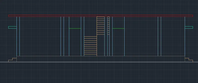
f) Draw the first floor outline
- Type 'CO' in the command line and enter to get copy tool
- Select the ground floor and paste it upper the ground floor
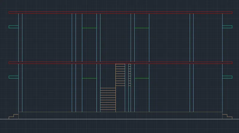
g) Draw the window
- Type 'RAY' in the command line and enter to get ray tool
- Draw rays of window from the ground floor plan
- Type 'OFF' in the command line and enter to get offset tool
- Offset 210cm from the plinth level and floor slab
- Offset 160cm from the new line to create window
- Offset 110cm from the first flight landing create window W3
- Offset 210cm from the new line to create W3
- Type 'TR' in the command line and enter to get trim tool
- Remove all unnecessary lines
- Draw the window interior
- Type 'OFF' in the command line and enter to get offset tool
- Offset all necessary lines
- Type 'TR' in the command line and enter to get trim tool
- Remove all unnecessary lines
- Type 'OFF' in the command line and enter to get offset tool
- Select windows and click the "Windows" layer in the layer tab
- Select glasses in the windows and click the "Glass" layer in the layer tab
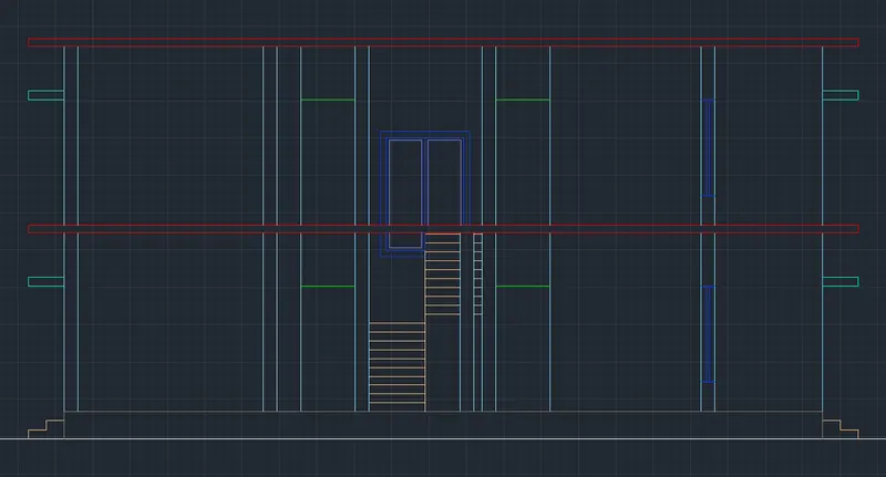
h) Draw the door interior
- Type 'OFF' in the command line and enter to get offset tool
- Offset 10cm from the door on all sides except bottom side
- Type 'REC' in the command line and enter to get rectangle
- Draw door knob using rectangle and keyhole
- Type 'C' in the command line and enter to get circle
- Draw the keyhole completely
- Type 'TR' in the command line and enter to get trim tool
- Remove all unnecessary lines
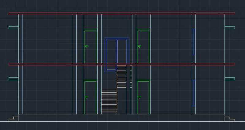
i) Draw lintel beam
- Type 'LA' in the command line and enter to get layers
- Create a new layer "Lintel beam"
- Type 'RAY' in the command line and enter to get ray tool
- Draw rays of sunshade to project lintel beam
- Type 'TR' in the command line and enter to get trim tool
- Remove all unnecessary lines
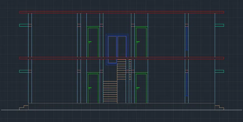
j) Draw the parapet wall at the terrace in the first floor
- Select the "Walls" layer
- Type 'RAY' in the command line and enter to get ray tool
- Draw rays of the parapet wall from the first floor plan
- Type 'OFF' in the command line and enter to get offset tool
- Offset 90cm from the floor slab
- Type 'TR' in the command line and enter to get trim tool
- Remove all unnecessary lines
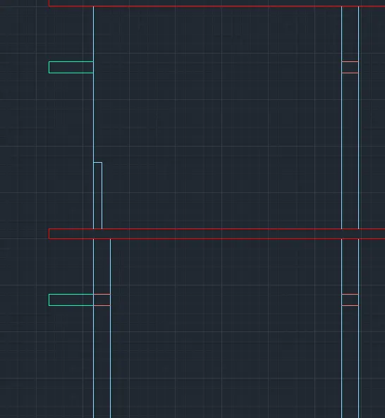
k) Draw the parapet wall at the second floor
- Select the "Walls" layer
- Type 'RAY' in the command line and enter to get ray tool
- Draw rays of the wall from first floor
- Type 'OFF' in the command line and enter to get offset tool
- Offset 90cm from the floor slab
- Type 'TR' in the command line and enter to get trim tool
- Remove all unnecessary lines
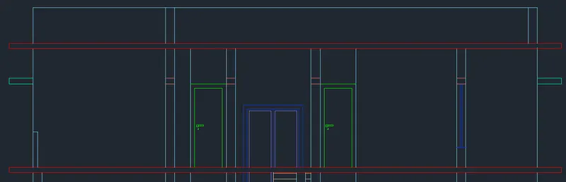
l) Draw the plinth beam
- Select "Plinth Beam" layer
- Type 'REC' in the command line and enter to get rectangle
- Draw a rectangle of 23cmx45cm to get plinth beam
- Type 'M' in the command line and enter to get move tools
- Align plinth beam in the midpoint of all of them
- Type 'CO' in the command line and enter to get copy tool
- Select the plinth beam and paste it in the center of all walls
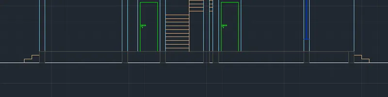
m) Draw the floor beam, Draw glass rail in the balcony
- Select "Floor Slab" layer and rename it to "Floor Slab and Beam"
- Type 'OFF' in the command line and enter to get offset tool
- Offset 30cm from the floor slab to the -y direction on first floor and second floor
- Type 'TR' in the command line and enter to get trim tool
- Remove all unnecessary lines
- Select "Glass" Layer
- Type 'REC' in the command line and enter to get rectangle
- Draw a rectangle of 5cmx90cm with 2cm offset from the floor slab
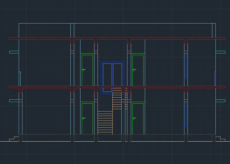
n) Hatching
- Select "Hatch" layer
- Type 'H' in the command line and enter to get hatch creation
- Pick internal point: Pick all the brick portions (Pattern: ANSI32)
- Pick internal point: Pick all the glasses (Pattern: SOLID, Colour: 171, Transparency: 64)
- Pick internal point: Pick all the plinth beam (Pattern: GRAVEL, Colour:8)
- Pick internal point: Pick all the lintel beam, floor slab (Pattern: AR-CONC, Colour:252)
- Pick internal point: Pick all the sand fill portions (Pattern: AR-SAND)
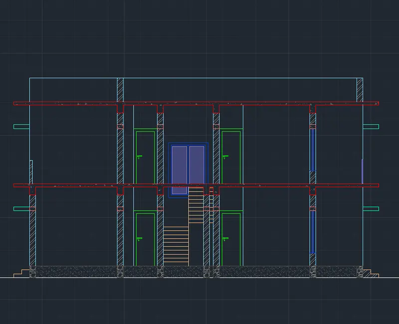
o) Insert dimensions in the section-AA
- Turn on "Dimensions" layer
- Dimension style is same as given above
- Type 'DIM' in the command line and enter to get dimension line
- Mark all necessary dimensions
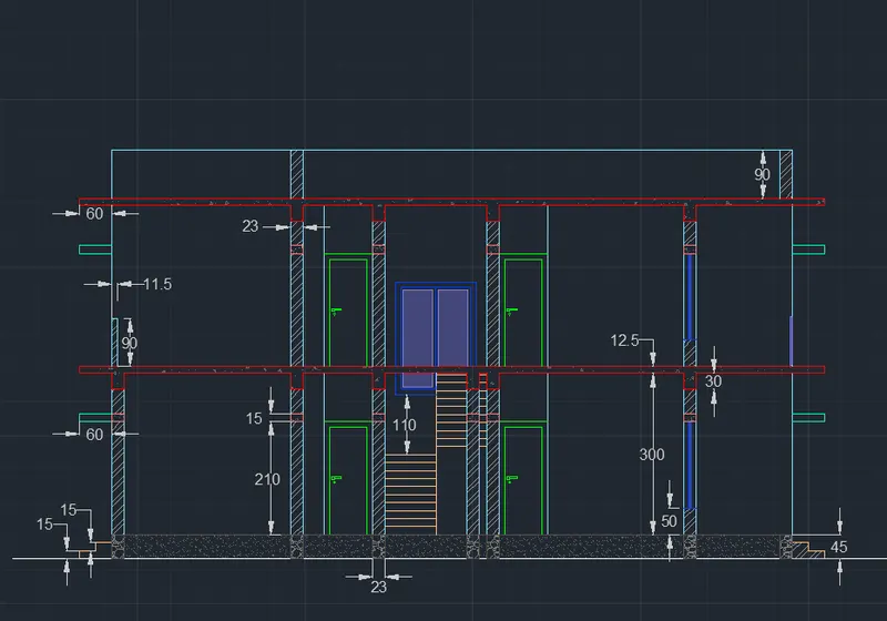
p) Insert text and annotations
- Turn on "Texts and Annotations" layer
- Type 'MTEXT' in the command line and enter to get multi line text
- Type text wherever required
- Type 'MLD' in the command line and enter to get multi leader tool
- Draw multileaders to represent the details of the section-AA
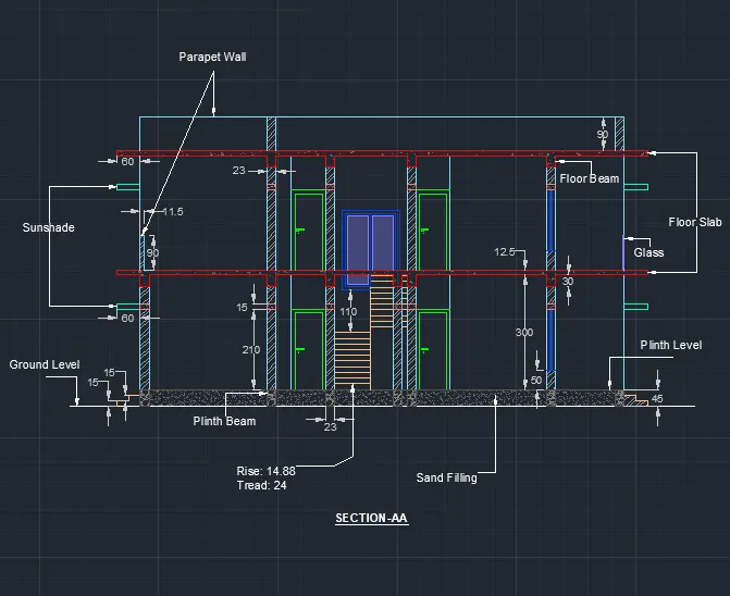
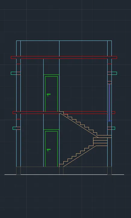
6. Draw the section-BB
Rotated the drawing as shown below to draw section-AA
a) Draw the outline of section-BB
- Turn off "Dimensions", "Texts and Annotations", and "Hatches" layers
- Select "Wall" layer
- Type 'RAY' in the command line and enter to get ray tool
- Draw rays of wall from the ground floor plan
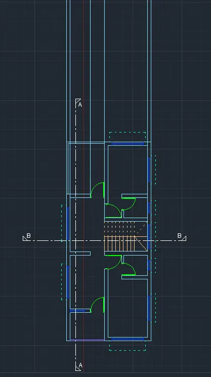
- Type 'RAY' in the command line and enter to get ray tool
- Draw rays from the elevation to draw section-BB
- Use different layers for different rays according to the desired design
- Draw rays from the elevation to draw section-BB
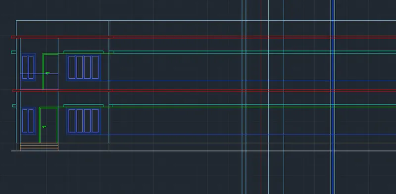
- Type 'TR' in the command line and enter to get trim tool
- Remove all unnecessary lines
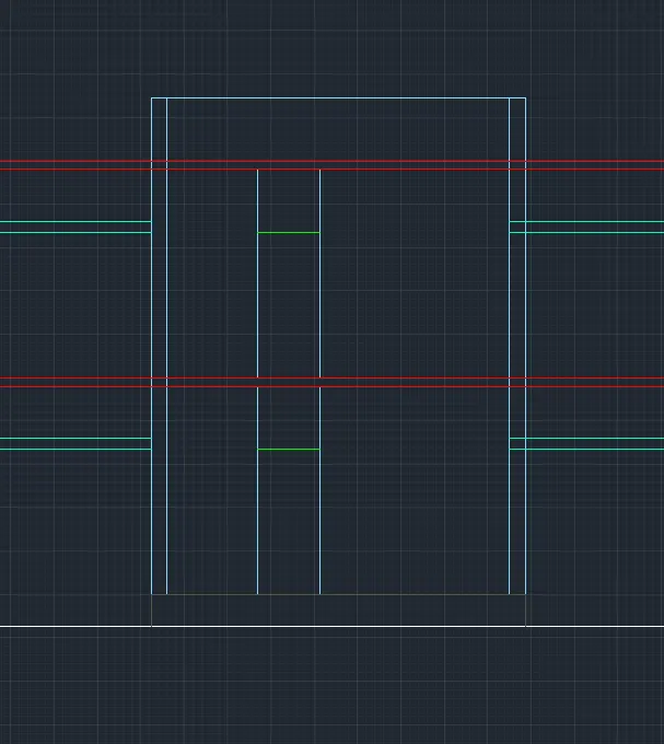
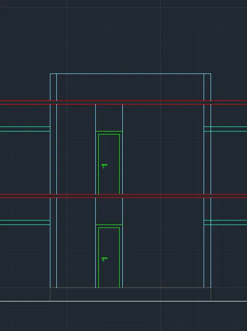
b) Draw the door interior
- Type 'OFF' in the command line and enter to get offset tool
- Offset 10cm from the door on all sides except bottom side
- Type 'REC' in the command line and enter to get rectangle
- Draw door knob using rectangle and keyhole
- Type 'C' in the command line and enter to get circle
- Draw the keyhole completely
- Type 'TR' in the command line and enter to get trim tool
- Remove all unnecessary lines
- Select all the doors and its parts and click "Doors" layer
c) Draw the stairs
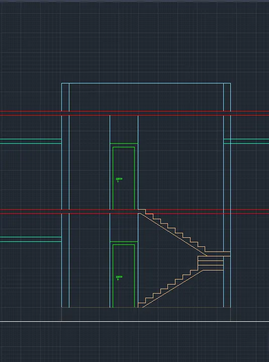
- Select "Stairs" as the current layer
- Type 'RAY' in the command line and enter to get ray tool
- Draw rays of stairs from the ground floor plan
- Type 'OFF' in the command line and enter to get offset tool
- Offset 14.88cm from the plinth level to desired length
- Type 'L' in the command line and enter to get line
- Draw a line at 32 degree angle from the base to the first landing
- Draw a line at 32 degree angle from the first landing to the floor slab
- Type 'TR' in the command line and enter to get trim tool
- Remove all unnecessary lines
- Select stairs and click the "Stairs" layer in the layer tab
d) Draw the window W3
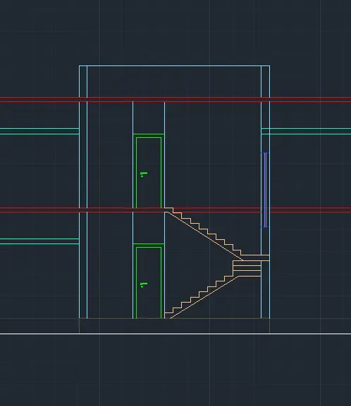
- Select "Glass" layer as the current layer
- Type 'RAY' in the command line and enter to get ray tool
- Draw rays of glass of window from the plan
- Type 'OFF' in the command line and enter to get offset tool
- Offset 110cm from the 10th step
- Offset 210cm from the new line
- Type 'TR' in the command line and enter to get trim tool
- Remove all unnecessary lines
- Select window W3 and click the "Windows" layer in the layer tab
e) Draw the sunshades
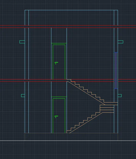
- Select "Sunshades" layer as the current layer
- Type 'RAY' in the command line and enter to get ray tool
- Draw rays of sunshades of window from both plans
- Type 'TR' in the command line and enter to get trim tool
- Remove all unnecessary lines
f) Draw the floor slab
- Select "Floor slab" layer as the current layer
- Type 'OFF' in the command line and enter to get offset tool
- Offset 20cm from the wall for both sides for ground floor
- Offset 30cm from the wall for both sides for first floor
- Type 'TR' in the command line and enter to get trim tool
- Remove all unnecessary lines
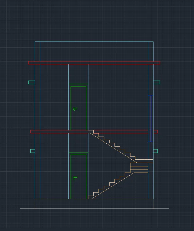
g) Draw the floor beam
- Select "Floor Slab and Beam" as the current layer
- Type 'OFF' in the command line and enter to get offset tool
- Offset 30cm from the floor slab to the -y direction on first floor and second floor
- Type 'TR' in the command line and enter to get trim tool
- Remove all unnecessary lines
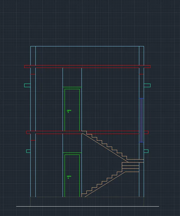
h) Draw the lintel beam
- Select "Lintel Beam" as the current layer
- Type 'RAY' in the command line and enter to get ray tool
- Draw rays of sunshade to project lintel beam
- Type 'TR' in the command line and enter to get trim tool
- Remove all unnecessary lines
- Type 'CO' in the command line and enter to get copy tool
- Select the lintel beam and paste it above the W3 window
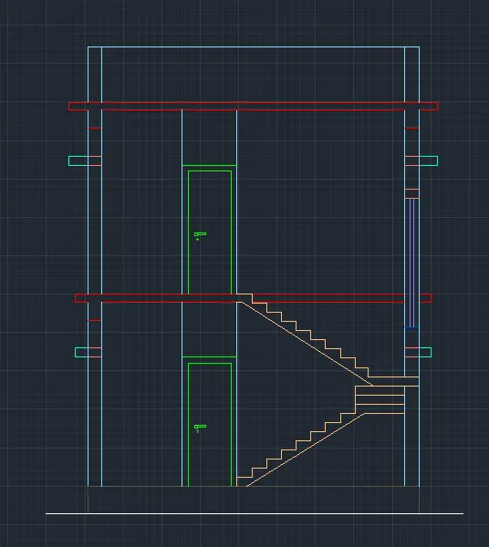
i) Draw the parapet wall
- Select "Walls" as the current layer
- Type 'RAY' in the command line and enter to get ray tool
- Draw rays of wall to project the parapet wall seperation
- Type 'TR' in the command line and enter to get trim tool
- Remove all unnecessary lines
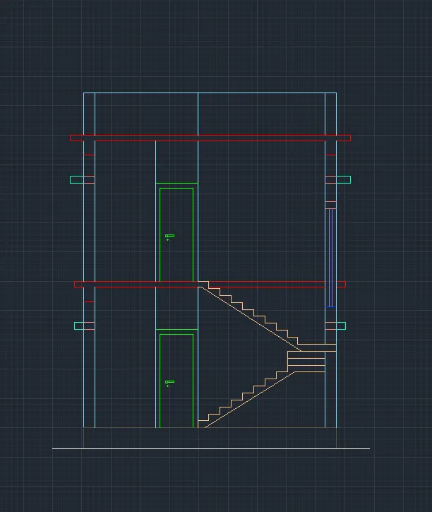
j) Draw the plinth beam
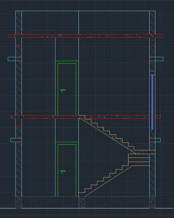
- Type 'CO' in the command line and enter to get copy tool
- Select the plinth beam and paste it in the center of all walls
k) Hatching
- Select "Hatch" layer as the current layer
- Type 'H' in the command line and enter to get hatch creation
- Pick internal point: Pick all the brick portions (Pattern: ANSI32)
- Pick internal point: Pick all the glasses (Pattern: SOLID, Colour: 171, Transparency: 64)
- Pick internal point: Pick all the plinth beam (Pattern: GRAVEL, Colour:8)
- Pick internal point: Pick all the lintel beam, floor slab, stair (second flight), sunshade (ground floor-left) (Pattern: AR-CONC, Colour:252)
- Pick internal point: Pick all the sand fill portions (Pattern: AR-SAND)
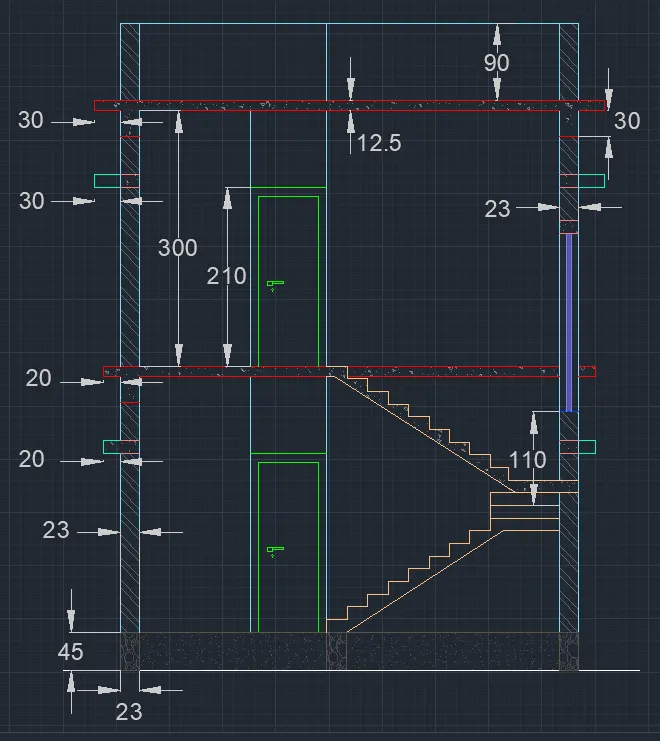
l) Insert dimensions in the section-BB
- Turn on "Dimensions" layer
- Dimension style is same as given above
- Type 'DIM' in the command line and enter to get dimension line
- Mark all necessary dimensions
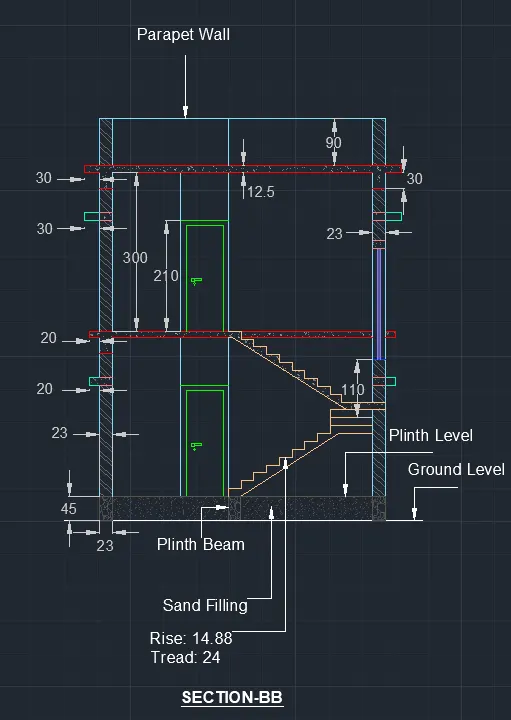
m) Insert text and annotations
- Turn on "Texts and Annotations" layer
- Type 'MTEXT' in the command line and enter to get multi line text
- Type text wherever required
- Type 'MLD' in the command line and enter to get multi leader tool
- Draw multileaders to represent the details of the section-AA
Part B: Structural Drawings
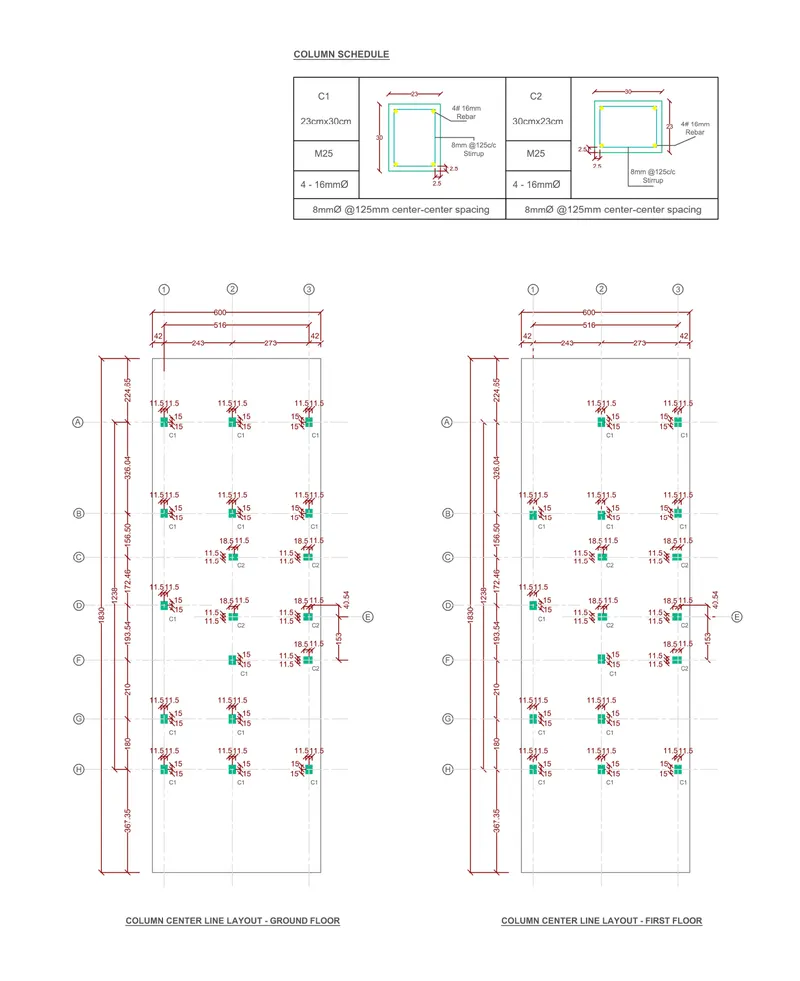
1. Draw column centerline layout
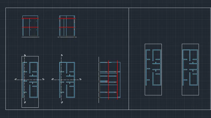
a) Draw the outline of the column centerline layout
- Turn off "Dimensions", "Texts and Annotations", "Sunshades", "Windows", "Doors", "Stairs" and "Hatches" layers
- Turn on "Plot Area" layer
- Type 'CO' in the command line and enter to get copy tool
- Select the 'Ground Floor Plan' and 'First Floor Plan' and paste it inside another box
b) Draw the columns inside the plot area
- Type 'LA' in the command line and enter to get layer properties
- Create a new layer "Columns"
- Type 'REC' in the command line and enter to get rectangle
- Draw a rectangle of size 23cmx30cm and 30cmx23cm as columns
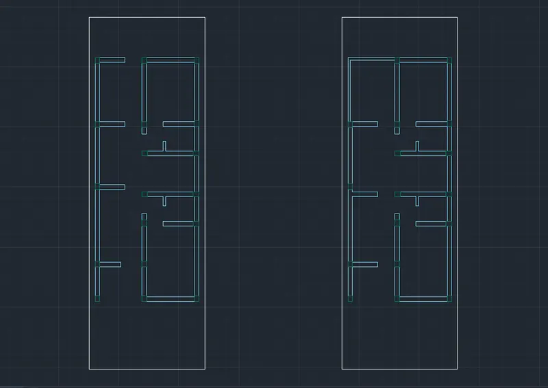
- Type 'CO' in the command line and enter to get copy tool
- Select the each column and place it according to the desired design
- Select all the columns drawn in the ground floor and paste it to the first floor
- Type 'TR' in the command line and enter to get trim tool
- Remove unnecessary columns in the first floor
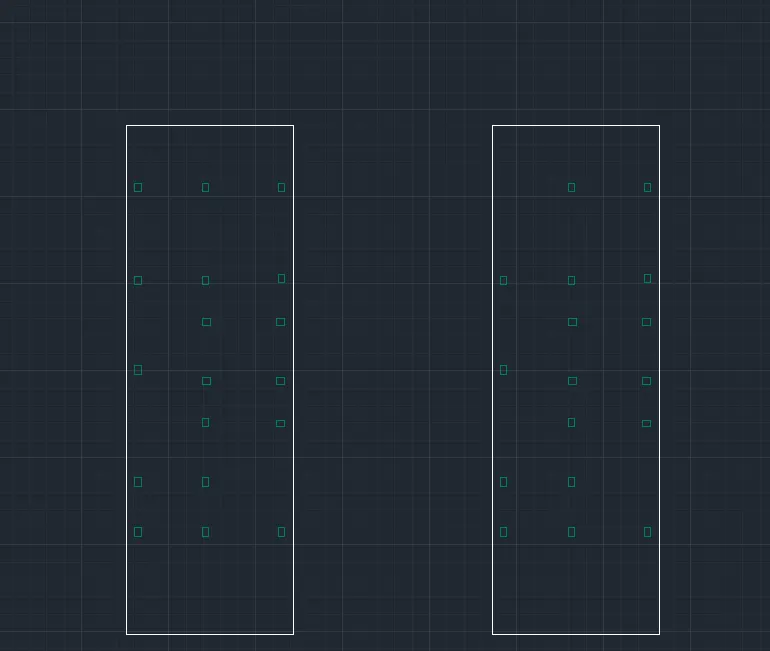
- Turn off "Walls" layer
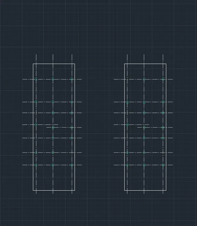
c) Draw the centerline
- Type 'LA' in the command line and enter to get layer properties
- Create a new layer "Center Lines" with linetype 'CENTER2'
- Type 'L' in the command line and enter to get line
- Draw a vertical line from the midpoint of top left colum to the midpoint of bottom left column and extent both sides
- Type 'OFF' in the command line and enter to get offset tool
- Offset 243cm from the new line to the x direction
- Offset 273cm from the new line to the x direction
- Type 'L' in the command line and enter to get line
- Draw a horizontalal line from the midpoint of bottom left colum to the midpoint of bottom right column and extent both sides
- Type 'OFF' in the command line and enter to get offset tool
- Offset 180cm from the new line to the y direction
- Offset 209.46cm from the new line to the y direction
- Offset 153cm from the new line to the y direction
- Offset 40.54cm from the new line to the y direction
- Offset 172.46cm from the new line to the y direction
- Offset 156.5cm from the new line to the y direction
- Offset 326.04cm from the new line to the y direction
- Type 'TR' in the command line and enter to get trim tool
- Remove unnecessary centerline
- Extent the trimmed lines
- Type 'CO' in the command line and enter to get copy tool
- Select all the centerlines drawn in the ground floor and paste it to the first floor
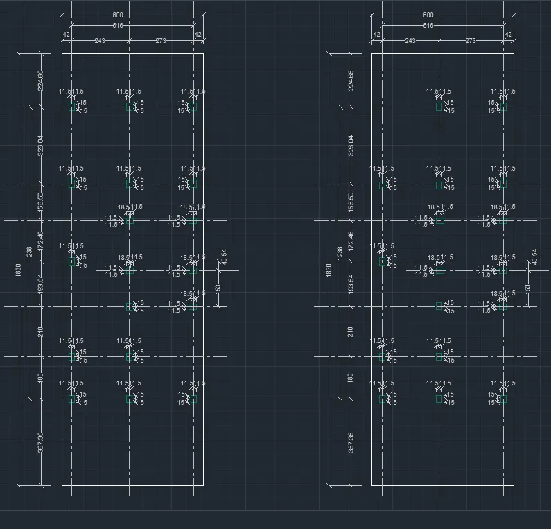
d) Insert dimensions in the column centerline layout
-
- Turn on "Dimensions" layer
- Dimension style
- In Lines and Arrows, Arrow 1 and Arrow 2 is changed to 'Oblique'
- All other dimension style features are same as the above
- Type 'DIM' in the command line and enter to get dimension line
- Mark all necessary dimensions
- Type 'CO' in the command line and enter to get copy tool
- Select all the dimensions drawn in the ground floor and paste it to the first floor
- Type 'E' in the command line and enter to get erase tool
- Remove unnecessary dimensions in the first floor
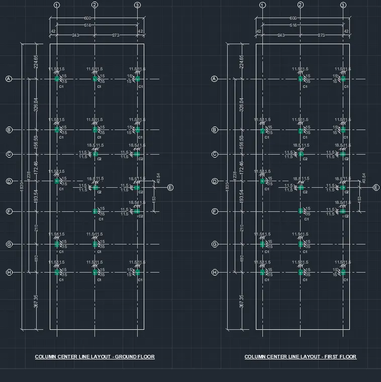
e) Insert texts and annotations in the column centerline layout
- Turn on "Texts and Annotations" layer
- Type 'MTEXT' in the command line and enter to get multi line text
- Type text wherever required
- Type 'C' in the command line and enter to get circle
- Draw a circle to contain centerline numbers and alphabets
- Type 'CO' in the command line and enter to get copy tool
- Copy the circle and place it according to the numbers and alphabets
- Select all the texts and shapes drawn in the ground floor and paste it to the first floor
- Type 'E' in the command line and enter to get erase tool
- Remove unnecessary texts in the first floor
f) Hatching the columns
- Type 'H' in the command line and enter to get hatch properties
- Pick internal point: Select all columns (Pattern: SOLID, Colour: 124)
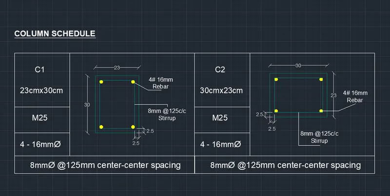
2. Prepare the column schedule
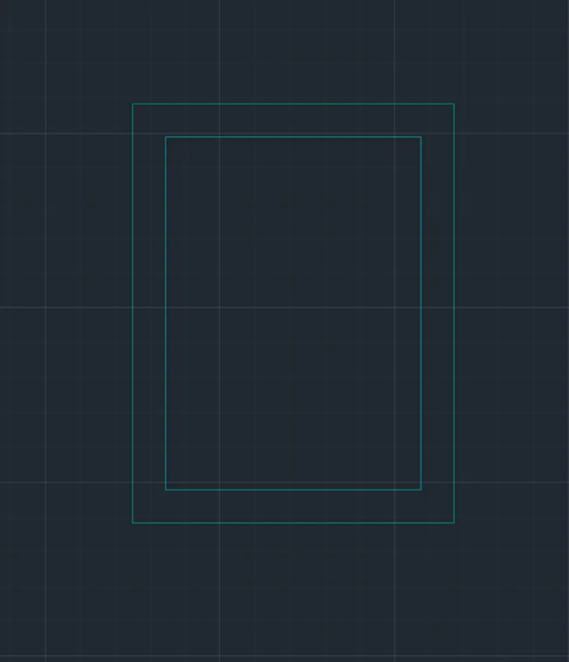
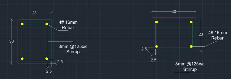
a) Draw the columns detail
- Type 'CO' in the command line and enter to get copy tool
- Copy the column 23cmx30cm drawn previously
- Type 'OFF' in the command line and enter to get offset tool
- Offset 2.5cm cover from the column inside
- Type 'LA' in the command line and enter to get layer properties
- Create a new layer "Stirrups"
- Select the new offset rectangle as "Stirrups"
- Type 'LA' in the command line and enter to get layer properties
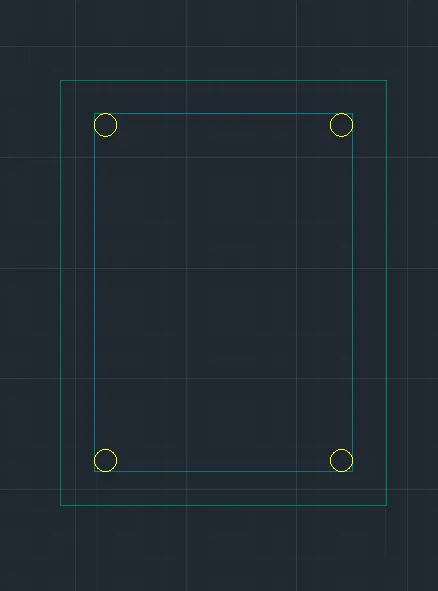
- Create a new layer "Rebar"
- Type 'C' in the command line and enter to get circle
- Draw a circle of diameter 1.6cm (16mm) with tan, tan, radius
- Type 'MI' in the command line and enter to get mirror tool
- Place the circle on the 4 corners with mirror tool
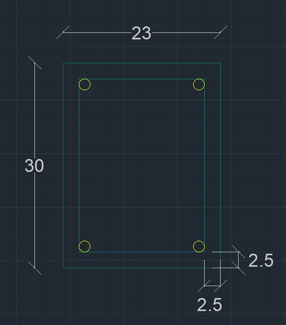
- Select "Dimensions" layer
- Dimension style
- In Lines and Arrows, Arrow 1 and Arrow 2 is changed to 'Oblique'
- In Fit, Overall scale is changed as '1.00'
- All other dimension style features are same as the above
- Type 'DIM' in the command line and enter to get dimension line
- Mark all necessary dimensions
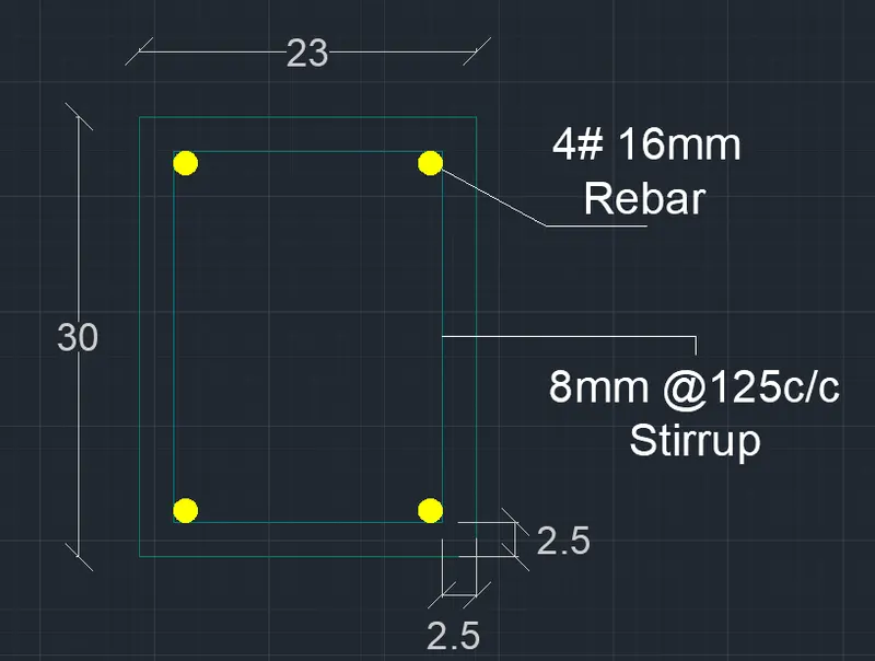
- Type 'H' in the command line and enter to get hatch properties
- Pick internal point: Select all rebars (Pattern: SOLID, Colour: 50)
- Type 'MLD' in the command line and enter to get multi leader tool
- Draw multileaders to represent the details of the rebars and stirrups
- Type 'RO' in the command line and enter to get rotate tool
- Select all and rotate with copy option
- Type 'REC' in the command line and enter to get rectangle
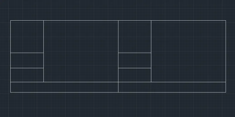
- Draw an outline boxes to contain columns and column details
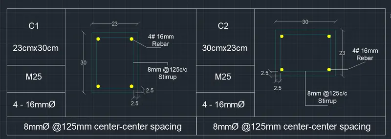
- Type 'MTEXT' in the command line and enter to get multi line text
- Type text wherever required
- Type 'MO' in the command line and enter to get move tool
- Select the columns and paste it inside the boxes
- Type 'SC' in the command line and enter to get scale tool
- Select all the items including boxes, columns, texts, leaders and dimensions
- Specify scale factor: 8
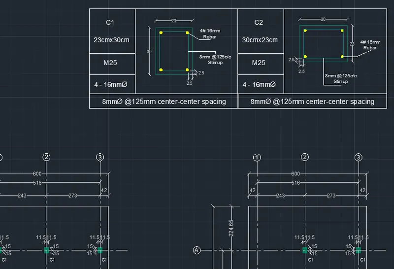
- Type 'MTEXT' in the command line and enter to get multi line text
- Type text wherever required
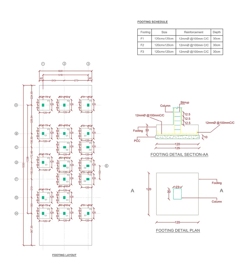
3. Draw the footing layout
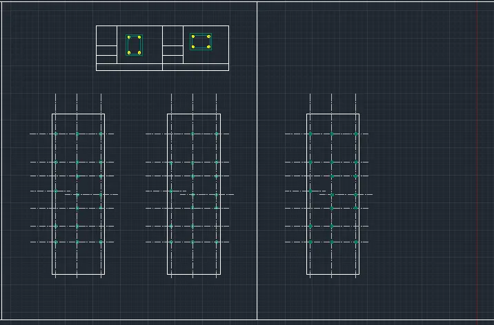
a) Draw the outline of the footing layout
- Turn off "Dimensions", "Texts and Annotations", and "Hatches" layers
- Type 'CO' in the command line and enter to get copy tool
- Select the 'Column layout - Ground Floor Plan' and paste it inside another box
b) Create footing and place it in the footing layout
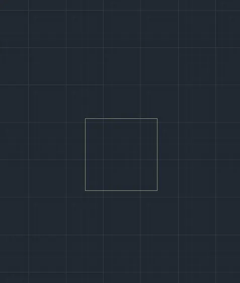
- Type 'LA' in the command line and enter to get layer properties
- Create a new layer "Footing"
- Type 'REC' in the command line and enter to get rectangle
- Draw a rectangle of size 120cmx120cm
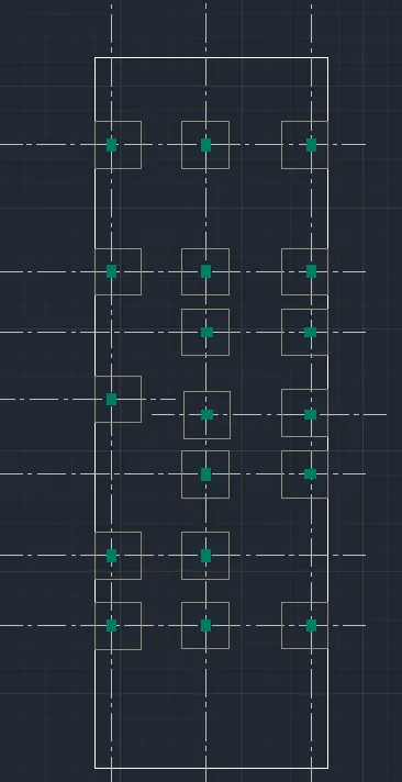
- Type 'CO' in the command line and enter to get copy tool
- Select the footing drawn and place it in the footing layout according to the desired design
c) Insert dimensions in the column centerline layout
- Turn on "Dimensions" layer
- Dimension style
- In Lines and Arrows, Arrow 1 and Arrow 2 is changed to 'Oblique'
- All other dimension style features are same as the above
- Type 'DIM' in the command line and enter to get dimension line
- Mark all necessary dimensions
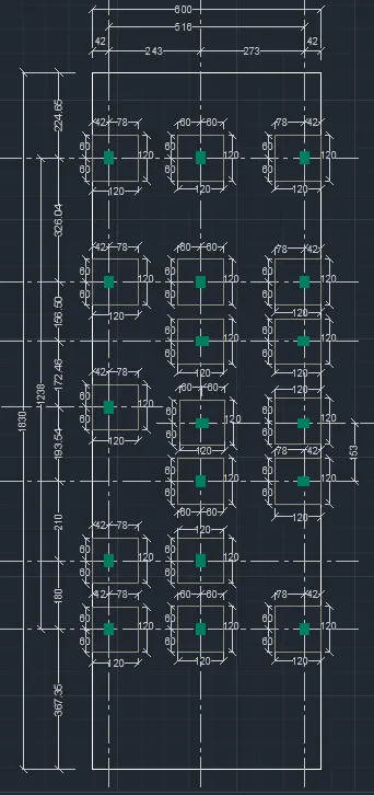
d) Insert texts and annotations in the column centerline layout
- Turn on "Texts and Annotations" layer
- Type 'MTEXT' in the command line and enter to get multi line text
- Type text wherever required
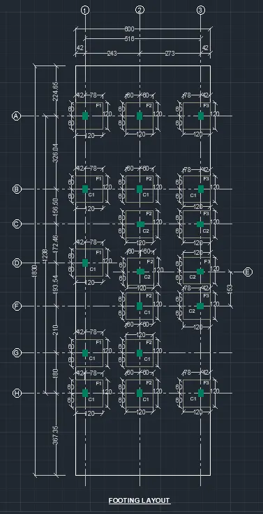
4. Draw the footing details
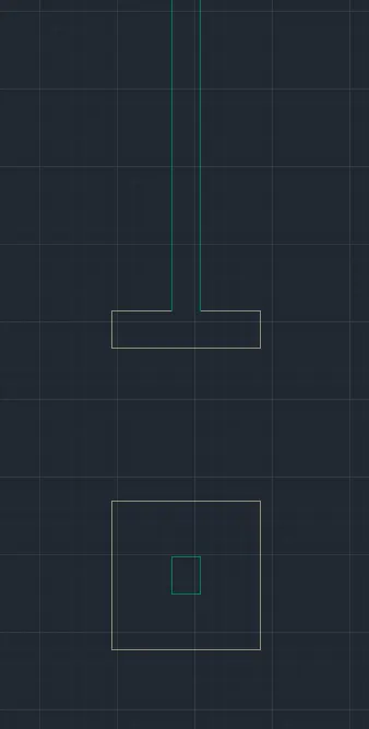
a) Draw the footing section outline
- Type 'CO' in the command line and enter to get copy tool
- Select a footing with column from the footing layout and paste it outside the plot area
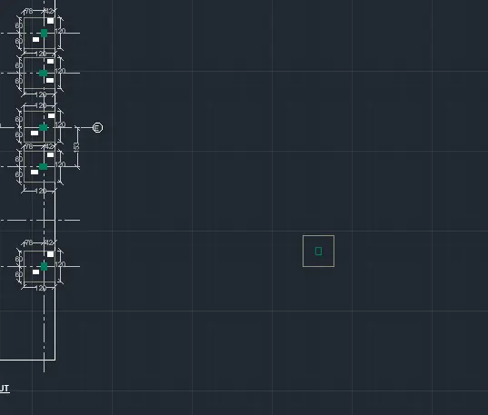
- Type 'RAY' in the command line and enter to get ray line
- Draw rays from footing and column
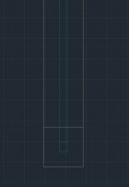
- Select the footing and click explode in the tool panel
- Type 'OFF' in the command line and enter to get offset tool
- Offset top line of the footing at some distance to create base of the footing section
- Offset 30cm from the new offset line in the y direction
- Type 'TR' in the command line and enter to get offset tool
- Remove all unnecessary lines
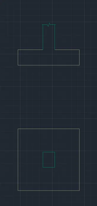
- Type 'BREAKLINE' in the command line and enter to get break line
- Draw break line between the column
- Type 'TR' in the command line and enter to get offset tool
- Remove all unnecessary lines
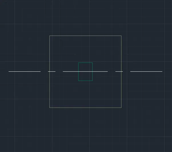
- Select "Section Lines" layer
- Type 'L' in the command line and enter to get line
- Draw a line from the midpoint of the footing through midpoint of column
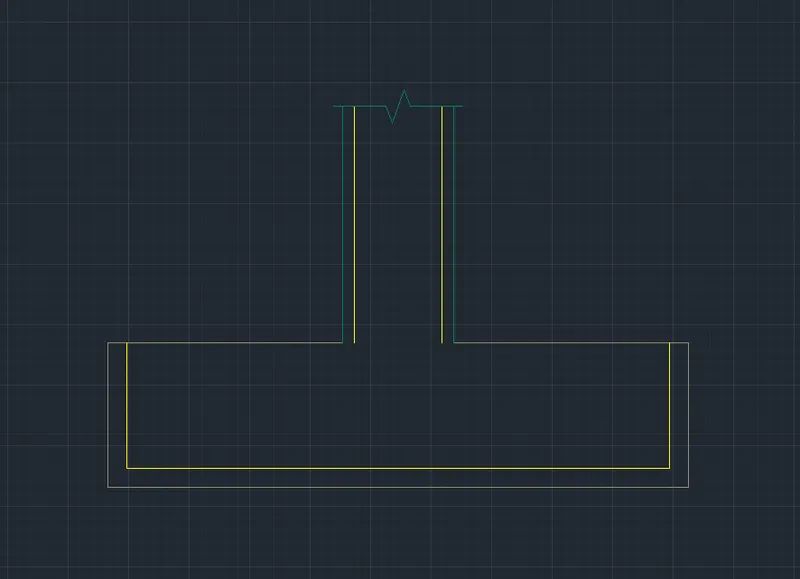
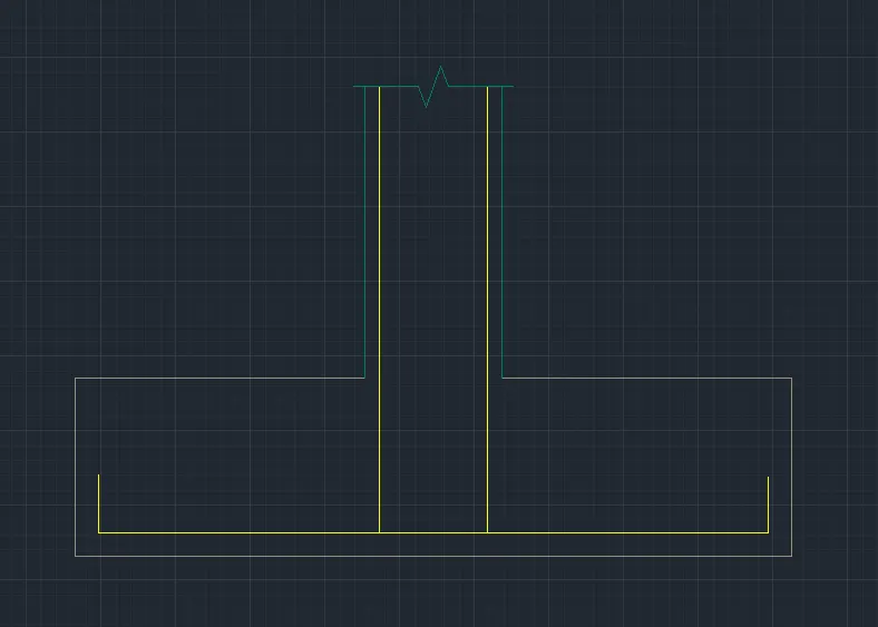
b) Draw the rebars in the section
- Select "Rebars" layer
- Type 'OFF' in the command line and enter to get offset tool
- Offset 4cm from the footing on 3 sides
- Offset 2.5cm from the column on both sides
- Type 'TR' in the command line and enter to get offset tool
- Remove all unnecessary lines
- Type 'EX' in the command line and enter to get extend tool
- Select the lines and extend the rebars
- Using stretch, reduce the length of rebars
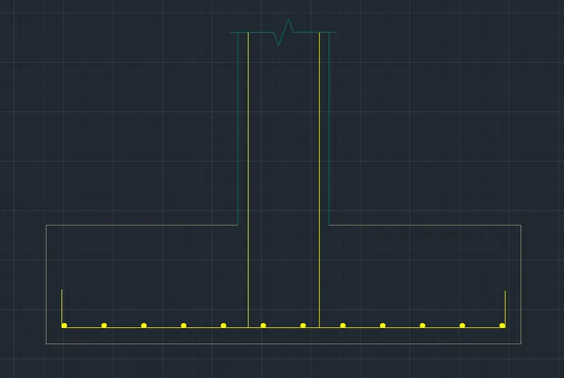
- Type 'C' in the command line and enter to get circle
- Draw a circle of diameter 1.2cm (12mm) with tan, tan, radius
- Type 'ARRAYPATH' in the command line and enter to get path array
- Select the circle as the object
- Select the horizontal rebar as the path and press enter
- Specify the space between the object as 10cm
- Type 'H' in the command line and enter to get hatch properties
- Pick internal point: Select all rebars (Pattern: SOLID, Colour: 50)
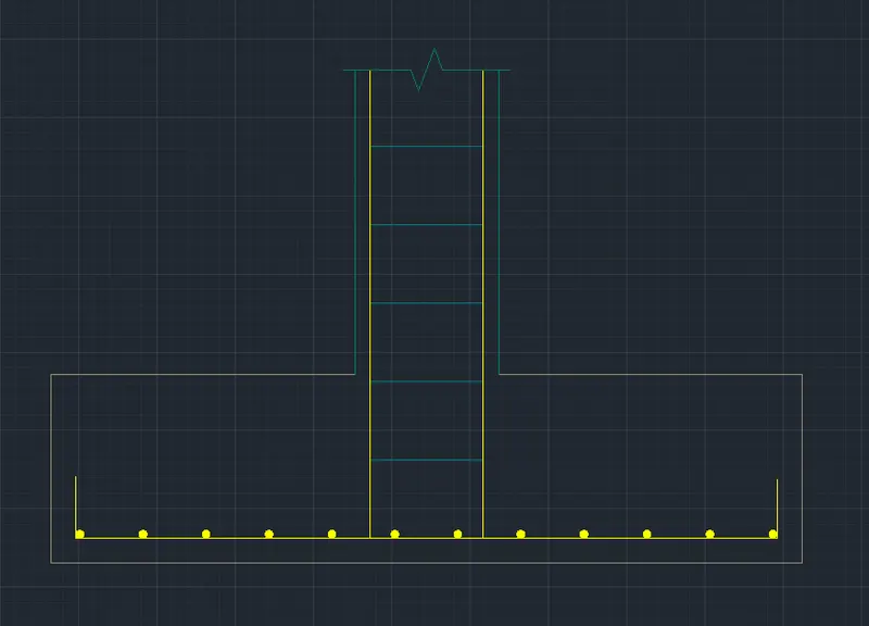
c) Draw the stirrups in the section
- Type 'OFF' in the command line and enter to get offset tool
- Offset 12.5cm from the horizontal rebar
- Select the new line and select "Stirrups" layer
- Type 'TR' in the command line and enter to get offset tool
- Remove all unnecessary lines
- Type 'OFF' in the command line and enter to get offset tool
- Offset 12.5cm from the stirrup using multiple option
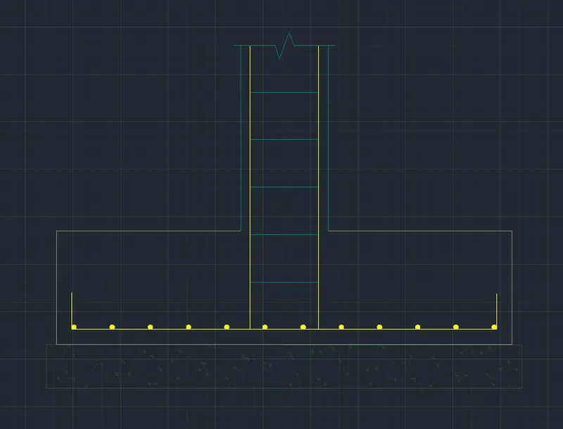
d) Draw the PCC under the footing
- Type 'LA' in the command line and enter to get layer properties
- Create a new layer "PCC"
- Type 'REC' in the command line and enter to get rectangle
- Draw a rectangle of 125cmx10cm under the footing
- Type 'H' in the command line and enter to get hatch properties
- Pick internal point: Select the PCC (Pattern: AR-CONC, Colour: 108)
e) Insert dimensions in the footing section and plan
- Select "Dimensions" layer
- All dimension style features are same as the above
- Dimension style
- In Lines and Arrows, Arrow 1 and Arrow 2 is changed to 'Oblique'
- In Fit, Overall scale is changed as '3.00'
- All other dimension style features are same as the above
- Type 'DIM' in the command line and enter to get dimension line
- Mark all necessary dimensions
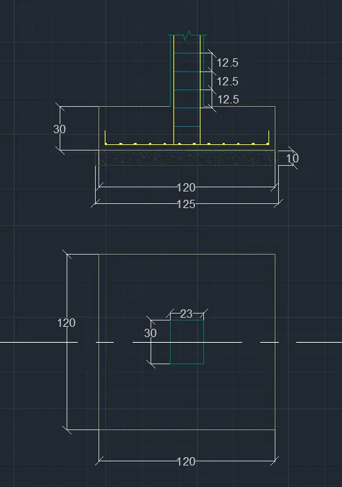
f) Insert texts and annotations in the footing section and plan
- Type 'MTEXT' in the command line and enter to get multi line text
- Type text wherever required
- Type 'MLD' in the command line and enter to get multi leader tool
- Draw multileaders to represent the details of the section and plan of the footing
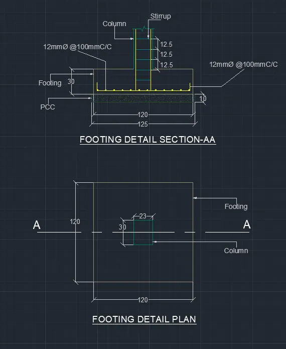
g) Scale the footing section and plan
- Type 'SC' in the command line and enter to get scale tool
- Select all the items including boxes, columns, texts, leaders and dimensions
- Specify scale factor: 4
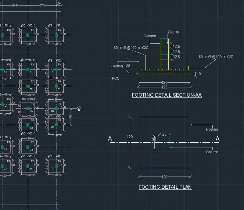
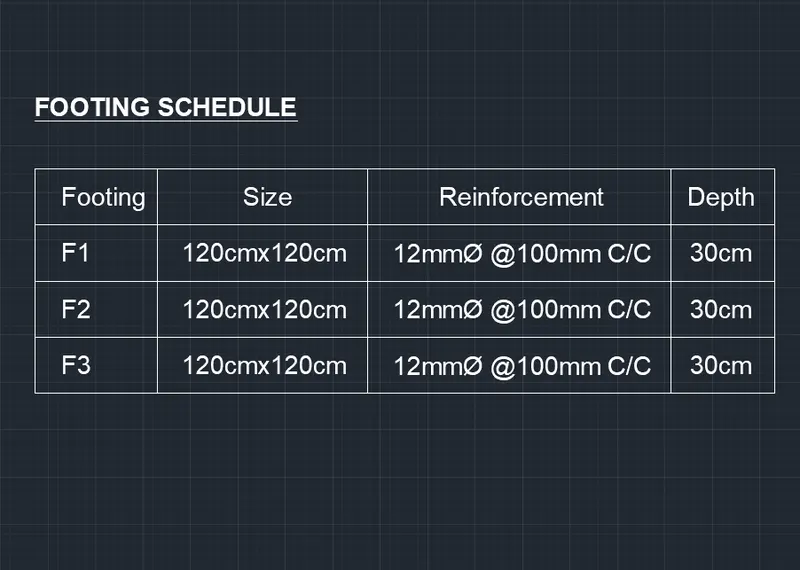
5. Prepare footing schedule
a) Create box
- Type 'REC' in the command line and enter to get rectangle
- Draw an outline boxes to contain footing details
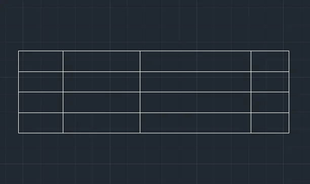
b) Insert texts and annotations in the footing schedule
- Type 'MTEXT' in the command line and enter to get multi line text
- Type text wherever required
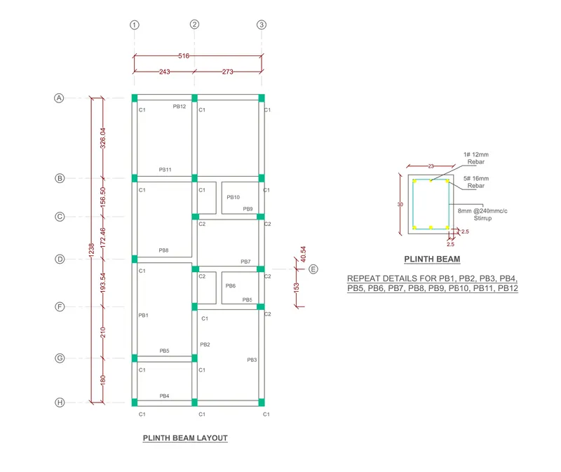
6. Draw the plinth beam layout
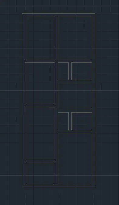
a) Draw the outline of plinth beam layout
- Turn off "Dimensions", "Texts and Annotations", "Sunshades", "Windows", "Doors", "Stairs", "Section Lines" and "Hatches" layers
- Turn on "Plot Area" layer
- Type 'CO' in the command line and enter to get copy tool
- Select the 'Ground Floor Plan' and paste it inside another box
- Type 'EX' in the command line and enter to get extend tool
- Select the wall lines and extend all lines
- Select all walls and select "Plinth Beam" layer
- Type 'OFF' in the command line and enter to get offset tool
- Select the lines near bathroom and offset 11.5cm in the -x direction
- Type 'TR' in the command line and enter to get offset tool
- Remove all unnecessary lines
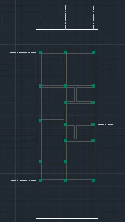
b) Draw column and section lines inside the plinth beam layout
- Turn on "Plot Area" layer
- Type 'CO' in the command line and enter to get copy tool
- Select the columns and centerlines from 'Column Center Line Layout - Ground Floor Plan' and paste it in 'Plinth Beam Layout'
- Type 'TR' in the command line and enter to get offset tool
- Remove all unnecessary lines
c) Insert dimensions in the plinth beam layout
- Turn on "Dimensions" layer
- Turn off "Plot Area" layer
- Dimension style
- In Lines and Arrows, Arrow 1 and Arrow 2 is changed to 'Oblique'
- All other dimension style features are same as the above
- Type 'DIM' in the command line and enter to get dimension line
- Mark all necessary dimensions
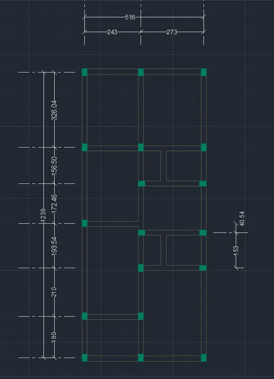
d) Insert texts and annotations in the footing schedule
- Type 'MTEXT' in the command line and enter to get multi line text
- Type text wherever required
- Type 'C' in the command line and enter to get circle
- Draw a circle to contain centerline numbers and alphabets
- Type 'CO' in the command line and enter to get copy tool
- Copy the circle and place it according to the numbers and alphabets
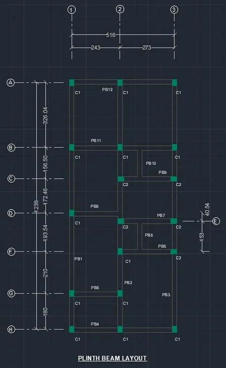
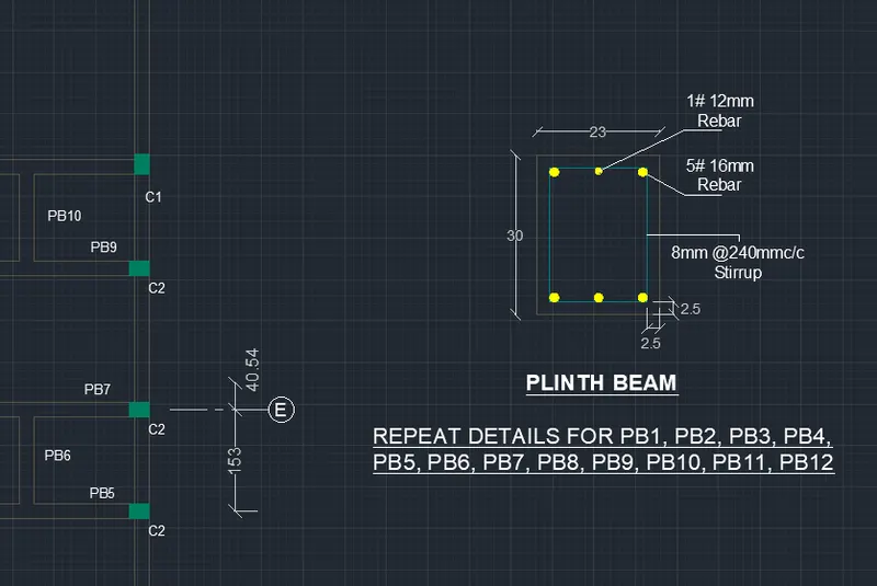
7. Draw plinth beam schedule
a) Draw plinth beam details
- Select "Plinth Beam" as the current layer
- Type 'REC' in the command line and enter to get rectangle
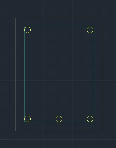
- Draw a rectangle of size 23cmx30cm as plinth beam
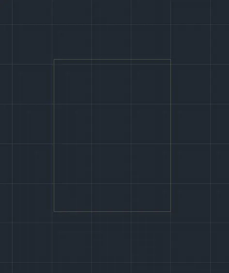
- Select the plinth beam drawn and click explode in the tool panel
- Select "Stirrups" as the current layer
- Type 'OFF' in the command line and enter to get offset tool
- Offset 2.5cm cover from the beam inside
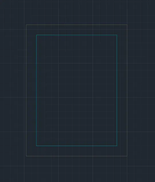
- Select "Rebars" as the current layer
- Type 'C' in the command line and enter to get circle
- Draw a circle of diameter 1.6cm (16mm) with tan, tan, radius
- Type 'MI' in the command line and enter to get mirror tool
- Place the circle on the 4 corners with mirror tool
- Type 'CO' in the command line and enter to get copy tool
- Copy the circle and place it in the lower middle
- Type 'C' in the command line and enter to get circle
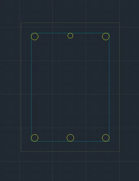
- Draw a circle of diameter 1.2cm (12mm)
- Type 'M' in the command line and enter to get move tool
- select the circle and place it in the upper middle
- Select "Dimensions" layer
- Dimension style
- In Lines and Arrows, Arrow 1 and Arrow 2 is changed to 'Oblique'
- In Fit, Overall scale is changed as '1.00'
- All other dimension style features are same as the above
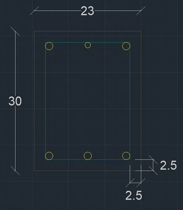
- Type 'DIM' in the command line and enter to get dimension line
- Mark all necessary dimensions
- Type 'H' in the command line and enter to get hatch properties
- Pick internal point: Select all rebars (Pattern: SOLID, Colour: 50)
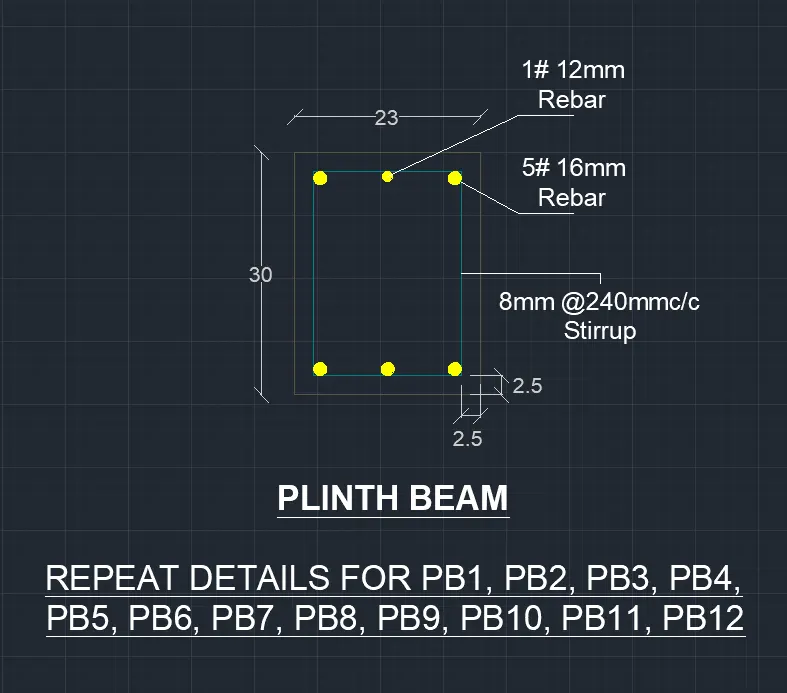
- Type 'MLD' in the command line and enter to get multi leader tool
- Draw multileaders to represent the details of the rebars and stirrups
- Type 'MTEXT' in the command line and enter to get multi line text
- Type text wherever required
- Type 'SC' in the command line and enter to get scale tool
- Select all the items including plinth beam, stirrups, rebars, texts, leaders and dimensions
- Specify scale factor: 8
8. Draw the lintel beam layout
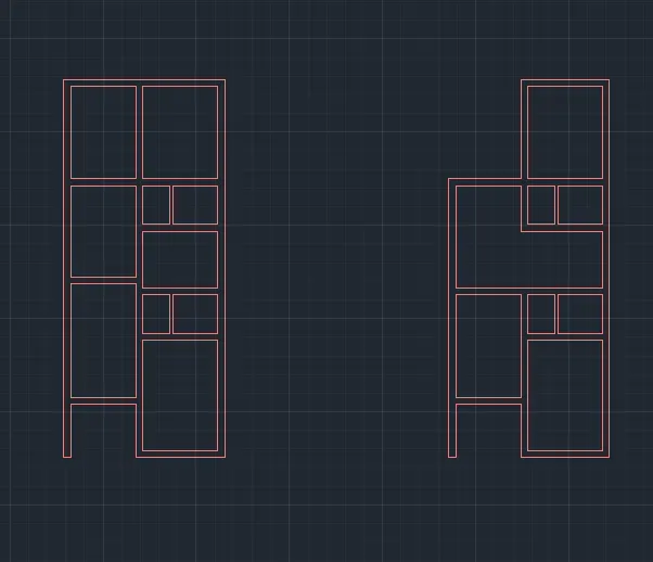
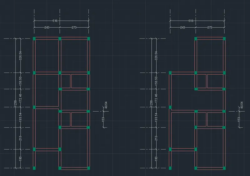
a) Draw the outline of plinth beam layout
- Turn off "Dimensions", "Texts and Annotations", "Sunshades", "Windows", "Doors", "Stairs", "Section Lines" and "Hatches" layers
- Turn on "Plot Area" layer
- Type 'CO' in the command line and enter to get copy tool
- Select the 'Ground Floor Plan', 'First Floor Plan' and paste it inside another box
- Type 'EX' in the command line and enter to get extend tool
- Select the wall lines and extend all lines
- Select all walls and select "Lintel Beam" layer
- Type 'TR' in the command line and enter to get offset tool
- Remove all unnecessary lines
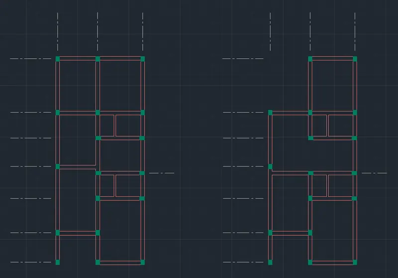
b) Draw column and section lines inside the lintel beam layout
- Turn on "Plot Area" layer
- Type 'CO' in the command line and enter to get copy tool
- Select the columns and centerlines from 'Column Center Line Layout - Ground Floor Plan' and paste it in 'lintel Beam Layout - Ground Floor' and 'lintel Beam Layout - First Floor'
- Type 'TR' in the command line and enter to get offset tool
- Remove all unnecessary lines
c) Insert dimensions in the plinth beam layout
- Turn on "Dimensions" layer
- Turn off "Plot Area" layer
- Dimension style
- In Lines and Arrows, Arrow 1 and Arrow 2 is changed to 'Oblique'
- All other dimension style features are same as the above
- Type 'DIM' in the command line and enter to get dimension line
- Mark all necessary dimensions
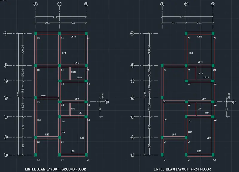
d) Insert texts and annotations in the footing schedule
- Type 'MTEXT' in the command line and enter to get multi line text
- Type text wherever required
- Type 'C' in the command line and enter to get circle
- Draw a circle to contain centerline numbers and alphabets
- Type 'CO' in the command line and enter to get copy tool
- Copy the circle and place it according to the numbers and alphabets
9. Draw lintel beam details
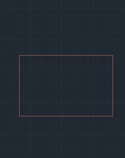
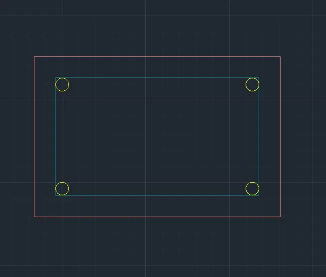
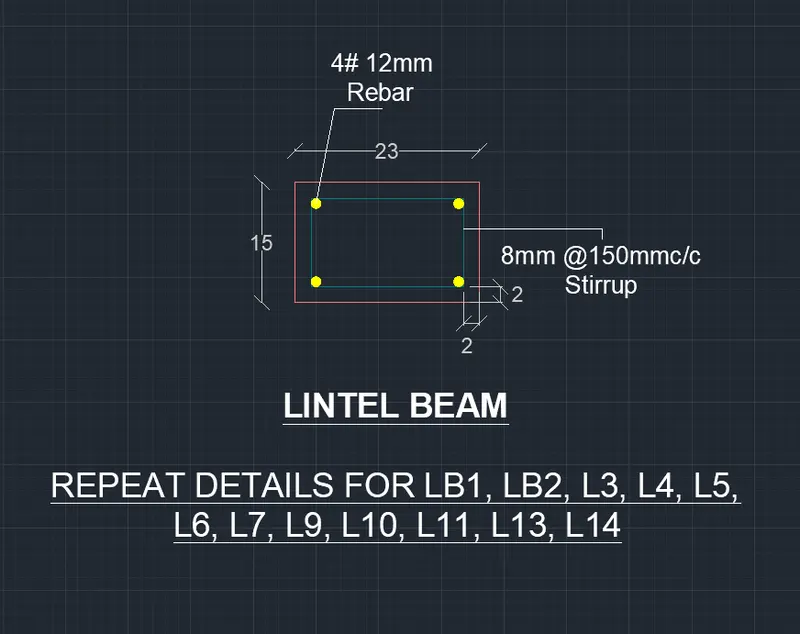
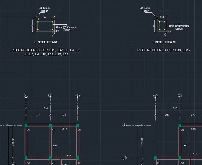
a) Draw lintel beam details of 23cmx15cm
- Select "lintel Beam" as the current layer
- Type 'REC' in the command line and enter to get rectangle
- Draw a rectangle of size 23cmx15cm as lintel beam
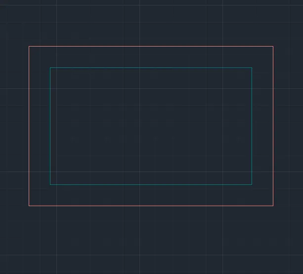
- Select "Stirrups" as the current layer
- Type 'OFF' in the command line and enter to get offset tool
- Offset 2cm cover from the beam inside
- Select "Rebars" as the current layer
- Type 'C' in the command line and enter to get circle
- Draw a circle of diameter 1.2cm (12mm) with tan, tan, radius
- Type 'MI' in the command line and enter to get mirror tool
- Place the circle on the 4 corners with mirror tool
- Select "Dimensions" layer
- Dimension style
- In Lines and Arrows, Arrow 1 and Arrow 2 is changed to 'Oblique'
- In Fit, Overall scale is changed as '1.00'
- All other dimension style features are same as the above
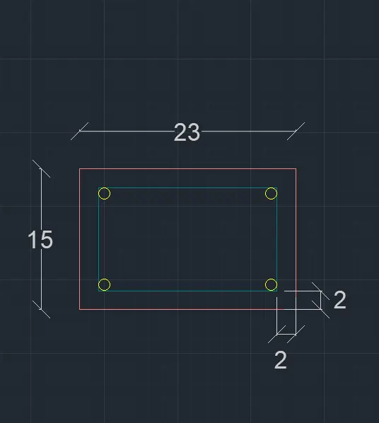
- Type 'DIM' in the command line and enter to get dimension line
- Mark all necessary dimensions
- Type 'H' in the command line and enter to get hatch properties
- Pick internal point: Select all rebars (Pattern: SOLID, Colour: 50)
- Type 'MLD' in the command line and enter to get multi leader tool
- Draw multileaders to represent the details of the rebars and stirrups
- Type 'MTEXT' in the command line and enter to get multi line text
- Type text wherever required
b) Draw lintel beam details of 11.5cmx15cm
- Select "lintel Beam" as the current layer
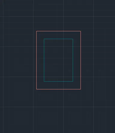
- Type 'REC' in the command line and enter to get rectangle
- Draw a rectangle of size 11.5cmx15cm as plinth beam
- Select "Stirrups" as the current layer
- Type 'OFF' in the command line and enter to get offset tool
- Offset 2cm cover from the beam inside
- Select "Rebars" as the current layer
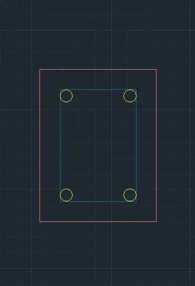
- Type 'C' in the command line and enter to get circle
- Draw a circle of diameter 1.2cm (12mm) with tan, tan, radius
- Type 'MI' in the command line and enter to get mirror tool
- Place the circle on the 4 corners with mirror tool
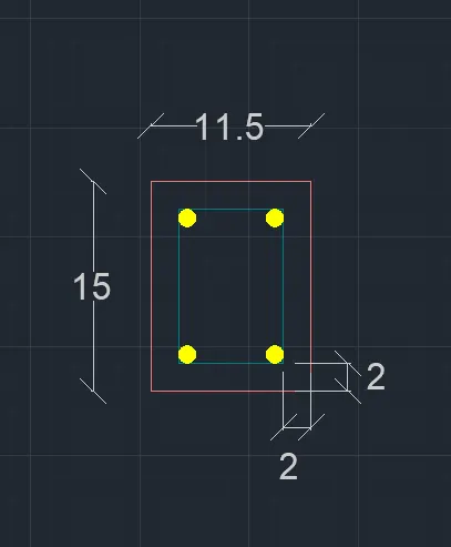
- Select "Dimensions" layer
- Dimension style
- In Lines and Arrows, Arrow 1 and Arrow 2 is changed to 'Oblique'
- In Fit, Overall scale is changed as '1.00'
- All other dimension style features are same as the above
- Type 'DIM' in the command line and enter to get dimension line
- Mark all necessary dimensions
- Type 'H' in the command line and enter to get hatch properties
- Pick internal point: Select all rebars (Pattern: SOLID, Colour: 50)
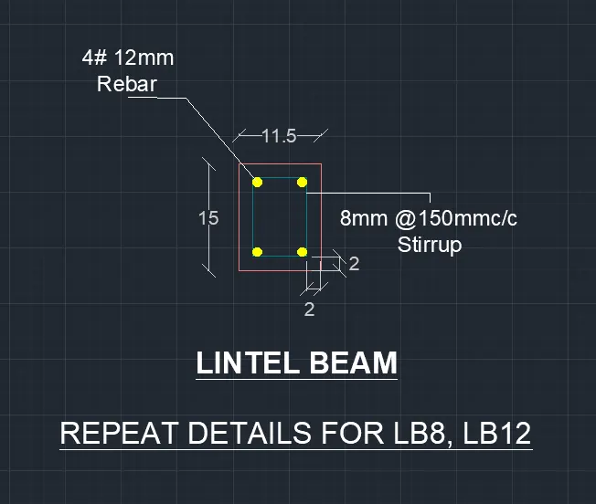
- Type 'MLD' in the command line and enter to get multi leader tool
- Draw multileaders to represent the details of the rebars and stirrups
- Type 'MTEXT' in the command line and enter to get multi line text
- Type text wherever required
- Type 'SC' in the command line and enter to get scale tool
- Select all the items including plinth beam, stirrups, rebars, texts, leaders and dimensions
- Specify scale factor: 8
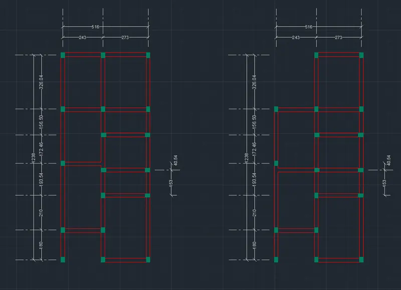
10. Draw the floor beam layout
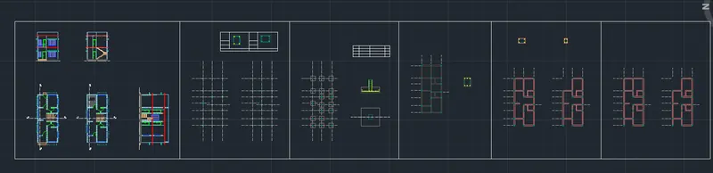
a) Draw the outline of floor beam layout
- Turn off "Dimensions" and "Texts and Annotations" layers
- Type 'CO' in the command line and enter to get copy tool
- Select the 'Lintel Beam - Ground Floor Plan', 'Lintel Beam - First Floor Plan' and paste it inside another box
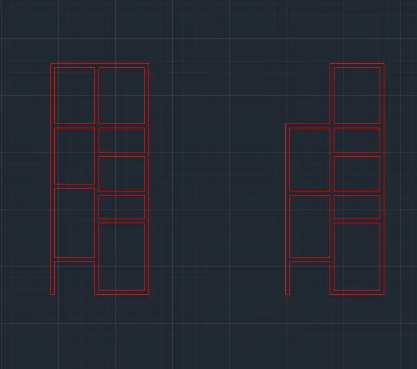
- Type 'EX' in the command line and enter to get extend tool
- Select the lintel lines and extend necessary lines
- Select all walls and select "Floor Slab and Beam" layer
- Type 'TR' in the command line and enter to get trim tool
- Remove all unnecessary lines
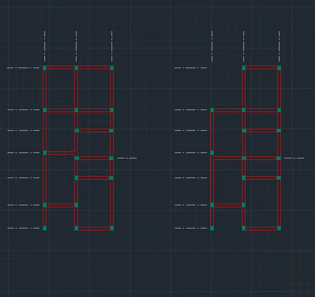
b) Draw floor beam and section lines inside the lintel beam layout
- Turn on "Plot Area" layer
- Type 'CO' in the command line and enter to get copy tool
- Select the columns and centerlines from 'Lintel Beam Layout - Ground Floor Plan' and 'lintel Beam Layout - First Floor' and paste it in 'Floor Beam Layout - Ground Floor' and 'Floor Beam Layout - First Floor'
c) Insert dimensions in the plinth beam layout
- Turn on "Dimensions" layer
- Turn off "Plot Area" layer
- Dimension style
- In Lines and Arrows, Arrow 1 and Arrow 2 is changed to 'Oblique'
- All other dimension style features are same as the above
- Type 'DIM' in the command line and enter to get dimension line
- Mark all necessary dimensions
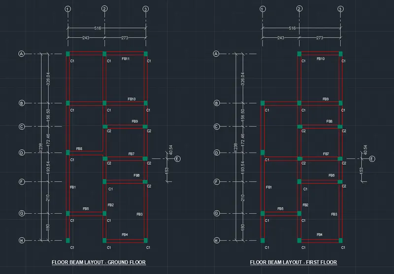
d) Insert texts and annotations in the footing schedule
- Type 'MTEXT' in the command line and enter to get multi line text
- Type text wherever required
- Type 'C' in the command line and enter to get circle
- Draw a circle to contain centerline numbers and alphabets
- Type 'CO' in the command line and enter to get copy tool
- Copy the circle and place it according to the numbers and alphabets
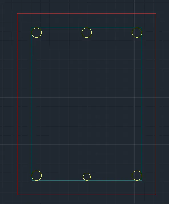
11. Draw floor beam details
- Select "Floor Slab and Beam" as the current layer
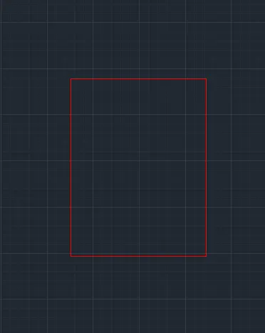
- Type 'REC' in the command line and enter to get rectangle
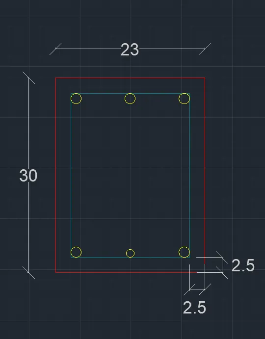
- Draw a rectangle of size 23cmx30cm as floor beam
- Select "Stirrups" as the current layer
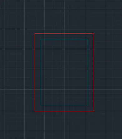
- Type 'OFF' in the command line and enter to get offset tool
- Offset 2.5cm cover from the beam inside
- Select "Rebars" as the current layer
- Type 'C' in the command line and enter to get circle
- Draw a circle of diameter 1.6cm (16mm) with tan, tan, radius
- Type 'MI' in the command line and enter to get mirror tool
- Place the circle on the 4 corners with mirror tool
- Type 'CO' in the command line and enter to get copy tool
- Copy the circle and place it in the upper middle
- Type 'C' in the command line and enter to get circle
- Draw a circle of diameter 1.2cm (12mm)
- Type 'M' in the command line and enter to get move tool
- select the circle and place it in the lower middle
- Select "Dimensions" layer
- Dimension style
- In Lines and Arrows, Arrow 1 and Arrow 2 is changed to 'Oblique'
- In Fit, Overall scale is changed as '1.00'
- All other dimension style features are same as the above
- Type 'DIM' in the command line and enter to get dimension line
- Mark all necessary dimensions
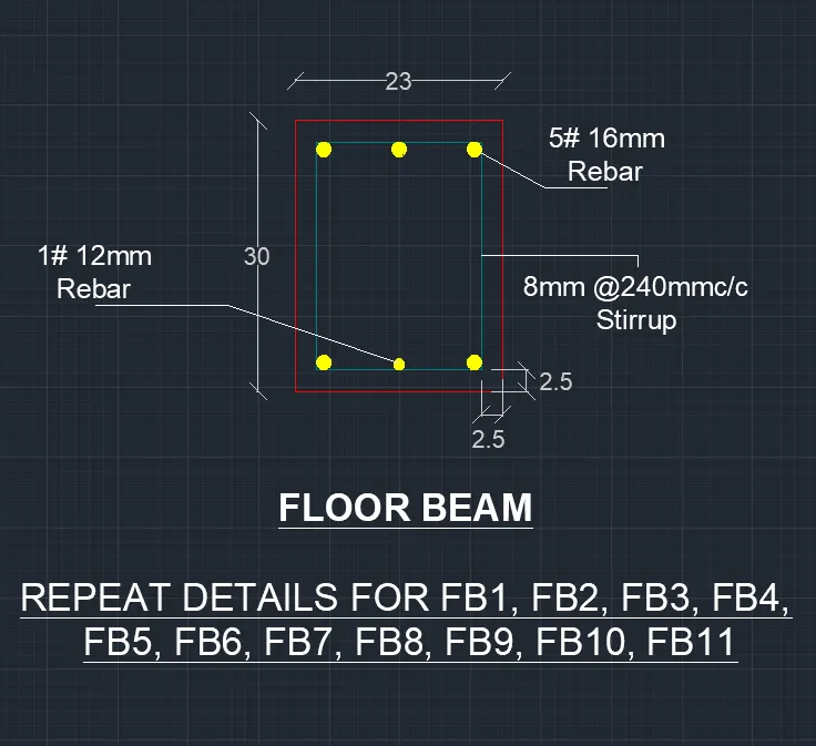
- Type 'H' in the command line and enter to get hatch properties
- Pick internal point: Select all rebars (Pattern: SOLID, Colour: 50)
- Type 'MLD' in the command line and enter to get multi leader tool
- Draw multileaders to represent the details of the rebars and stirrups
- Type 'MTEXT' in the command line and enter to get multi line text
- Type text wherever required
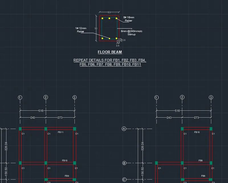
- Type 'SC' in the command line and enter to get scale tool
- Select all the items including plinth beam, stirrups, rebars, texts, leaders and dimensions
- Specify scale factor: 8
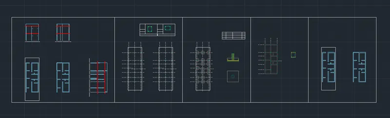
RESULT
An architectural plan for the provided plot size (18.3mx6m) with orientation facing East and develop relevant basic structural drawings such as column, beam and footing plan of a residential building is created. The final results are shown below. In this project, all dimensions are in centimeter 'cm', in someplace millimeter is also showed for standard sizing.
Part A: Architectural Drawings
1. Ground Floor Plan
2. First Floor Plan
3. Elevation
4. Section-AA
5. Section-BB
Part B: Structural Drawings
1. Column Schedule, Column Center Line Layout (Ground Floor and First Floor)
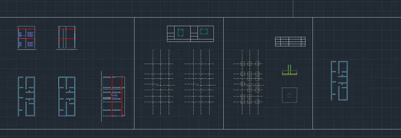
2. Footing Layout, Schedule and Details
3. Plinth Beam Layout and Beam Detail
4. Lintel Beam Layout (Ground Floor and First Floor) and Beam Details
5. Floor Beam Layout (Ground Floor and First Floor) and Beam Detail