Creation of geometries by Coordinate system methods using AutoCad
AIM
1. Create the geometries from P1 to P2 using all the coordinates system methods.
2. Create the geometries from P4, P5, P7, P8, P9, P10 using any coordinates system.
3. Draw the profile and the trusses using any coordinate system methods.
INTRODUCTION
A coordinate system is a system in geometry that employs one or more integers, or coordinates, to define the position of points or other geometric components on a manifold, such as Euclidean space, in a unique way. There are 3 types of coordinate systems, they are;
1. Absolute Coordinates
2. Relative Coordinates
- Relative Rectangular Coordinates
- Relative Polar Coordinates
3. Direct Distance Entry
PROCEDURES
AIM-1
P1
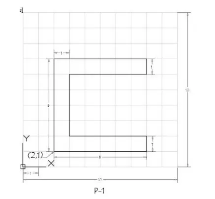
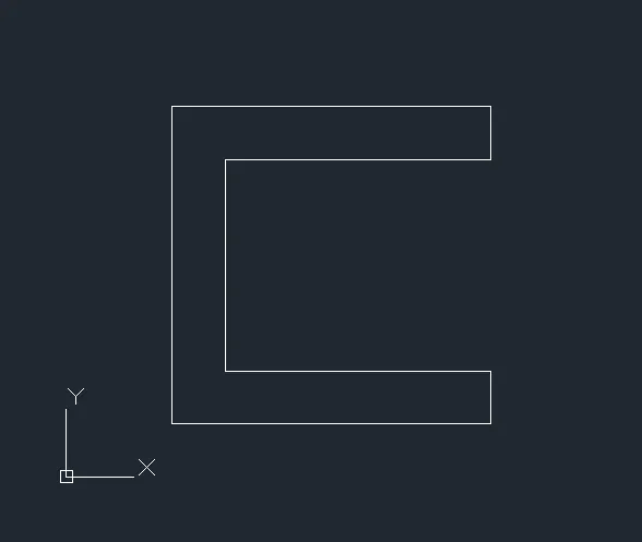
a. Absolute Coordinates System
- Start the AutoCAD software, use the Imperial Template and the Decimal Units to draft.
- Select Line to draw the orgin (2,1)
- Specify the next point (8,1)
- Specify the next point (8,2)
- Specify the next point (3,2)
- Specify the next point (3,6)
- Specify the next point (8,6)
- Specify the next point (8,7)
- Specify the next point (2,7)
- Then, the last point was Closed 'C' to point in the orgin (2,1)
b. Relative Rectangular Coordinates
- Start the AutoCAD software, use the Imperial Template and the Decimal Units to draft.
- Select Line to draw the orgin (2,1)
- Specify the next point (@6,0)
- Specify the next point (@0,1)
- Specify the next point (@-5,0)
- Specify the next point (@0,4)
- Specify the next point (@5,0)
- Specify the next point (@0,1)
- Specify the next point (@-6,0)
- Then, the last point was Close command 'C' to point in the orgin (2,1)
c. Relative Polar Coordinates
- Start the AutoCAD software, use the Imperial Template and the Decimal Units to draft.
- Select Line to draw the orgin (2,1)
- Specify the next point (@6<0)
- Specify the next point (@1<90)
- Specify the next point (@5<180)
- Specify the next point (@4<90)
- Specify the next point (@5<0)
- Specify the next point (@1<90)
- Specify the next point (@6<180)
- Then, the last point was Close command 'C' to point in the orgin (2,1)
P2
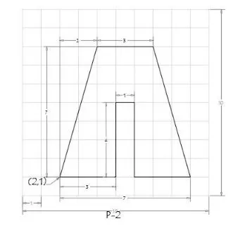
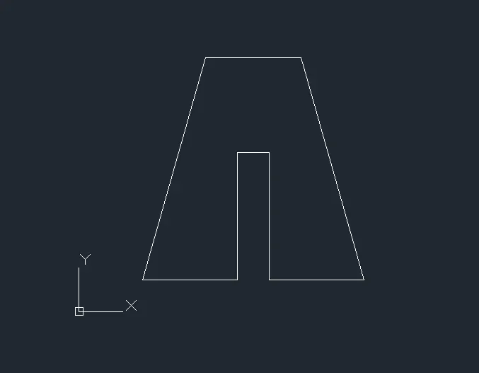
a. Absolute Coordinates System
- Start the AutoCAD software, use the Imperial Template and the Decimal Units to draft.
- Select Line to draw the orgin (2,1)
- Specify the next point (5,1)
- Specify the next point (5,5)
- Specify the next point (6,5)
- Specify the next point (6,1)
- Specify the next point (9,1)
- Specify the next point (7,8)
- Specify the next point (4,8)
- Then, the last point was Closed 'C' to point in the orgin (2,1)
b. Relative Rectangular Coordinates
- Start the AutoCAD software, use the Imperial Template and the Decimal Units to draft.
- Select Line to draw the orgin (2,1)
- Specify the next point (@3,0)
- Specify the next point (@0,4)
- Specify the next point (@1,0)
- Specify the next point (@0,-4)
- Specify the next point (@3,0)
- Specify the next point (@-2,7)
- Specify the next point (@-3,0)
- Then, the last point was Close command 'C' to point in the orgin (2,1)
c. Relative polar coordinates : It cannot be rendered using the relative polar coordinate system because there are no angles shown in the picture. Angles are required for directing the line in a relative polar coordinate. So with the help of AutoCAD, the assumed angle and length are 106° and 7.2801 respectively.
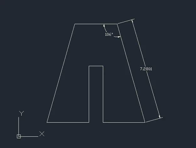
- Start the AutoCAD software, use the Imperial Template and the Decimal Units to draft.
- Select Line to draw the orgin (2,1)
- Specify the next point (@3<0)
- Specify the next point (@4<90)
- Specify the next point (@1<0)
- Specify the next point (@4<270)
- Specify the next point (@3<0)
- Specify the next point (@7.2801<106)
- Specify the next point (@3<180)
- Then, the last point was Close command 'C' to point in the orgin (2,1)
AIM-2
P4
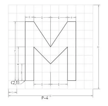

Drafted using Absolute Coordinates System
- Start the AutoCAD software, use the Imperial Template and the Decimal Units to draft.
- Select Line to draw the orgin (2,1)
- Specify the next point (3,1)
- Specify the next point (3,5)
- Specify the next point (5,3)
- Specify the next point (7,5)
- Specify the next point (7,1)
- Specify the next point (8,1)
- Specify the next point (8,8)
- Specify the next point (7,8)
- Specify the next point (5,5)
- Specify the next point (3,8)
- Specify the next point (2,8)
- Then, the last point was Closed 'C' to point in the orgin (2,1)
P5
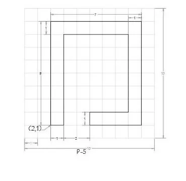
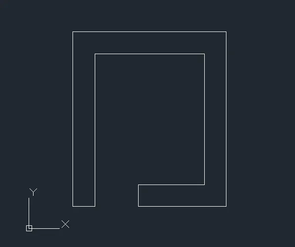
Drafted using Relative Rectangular Coordinates
- Start the AutoCAD software, use the Imperial Template and the Decimal Units to draft.
- Select Line to draw the orgin (2,1)
- Specify the next point (@1,0)
- Specify the next point (@0,7)
- Specify the next point (@5,0)
- Specify the next point (@0,-6)
- Specify the next point (@-3,0)
- Specify the next point (@0,-1)
- Specify the next point (@4,0)
- Specify the next point (@0,8)
- Specify the next point (@-7,0)
- Then, the last point was Close command 'C' to point in the orgin (2,1)
P7
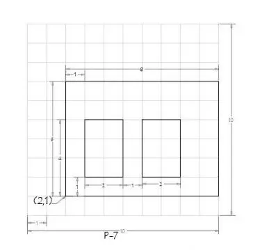
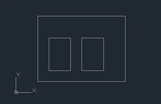
Drafted using Relative Rectangular Coordinates
- Start the AutoCAD software, use the Imperial Template and the Decimal Units to draft.
- Select Line to draw the orgin (2,1)
- Specify the next point (@8,0)
- Specify the next point (@0,6)
- Specify the next point (@-8,0)
- Then, the last point of that rectangle was Close command 'C' to point in the orgin (2,1)
- Then, select Line to draw the orgin (3,2) for another rectangle inside the first rectangle.
- Specify the next point (@2,0)
- Specify the next point (@0,3)
- Specify the next point (@-2,0)
- Then, the last point of that rectangle was Close command 'C' to point in the orgin (3,2)
- Then, again select Line to draw the orgin (6,2) for another rectangle inside the first rectangle.
- Specify the next point (@2,0)
- Specify the next point (@0,3)
- Specify the next point (@-2,0)
- Then, the last point of that rectangle was Close command 'C' to point in the orgin (6,2)
P8
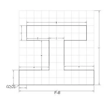
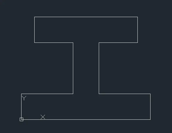
Drafted using Relative Polar Coordinates
- Start the AutoCAD software, use the Imperial Template and the Decimal Units to draft.
- Select Line to draw the orgin (0,0)
- Specify the next point (@10<0)
- Specify the next point (@2<90)
- Specify the next point (@4<180)
- Specify the next point (@4<90)
- Specify the next point (@3<0)
- Specify the next point (@2<90)
- Specify the next point (@8<180)
- Specify the next point (@2<270)
- Specify the next point (@3<0)
- Specify the next point (@4<270)
- Specify the next point (@4<180)
- Then, the last point was Close command 'C' to point in the orgin (0,0)
P9
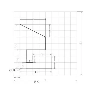
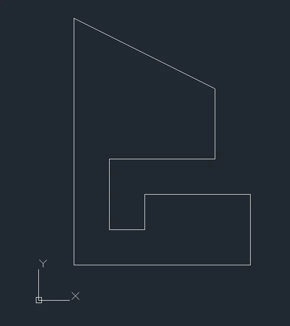
Drafted using Absolute Coordinates System
- Start the AutoCAD software, use the Imperial Template and the Decimal Units to draft.
- Select Line to draw the orgin (1,1)
- Specify the next point (6,1)
- Specify the next point (6,3)
- Specify the next point (3,3)
- Specify the next point (3,2)
- Specify the next point (2,2)
- Specify the next point (2,4)
- Specify the next point (5,4)
- Specify the next point (5,6)
- Specify the next point (1,8)
- Then, the last point was Closed 'C' to point in the orgin (1,1)
P10
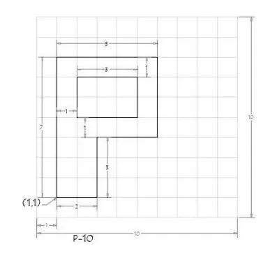
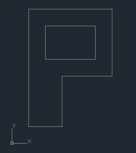
Drafted using Relative Rectangular Coordinates
- Start the AutoCAD software, use the Imperial Template and the Decimal Units to draft.
- Select Line to draw the orgin (1,1)
- Specify the next point (@2,0)
- Specify the next point (@0,3)
- Specify the next point (@3,0)
- Specify the next point (@0,4)
- Specify the next point (@-5,0)
- Then, the last point of that polygon was Close command 'C' to point in the orgin (1,1)
- Then, select Line to draw the orgin (2,5) for another rectangle inside the polygon.
- Specify the next point (@3,0)
- Specify the next point (@0,2)
- Specify the next point (@-3,0)
- Then, the last point of that rectangle was Close command 'C' to point in the orgin (2,5)
AIM-3
Profile-Wood
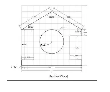
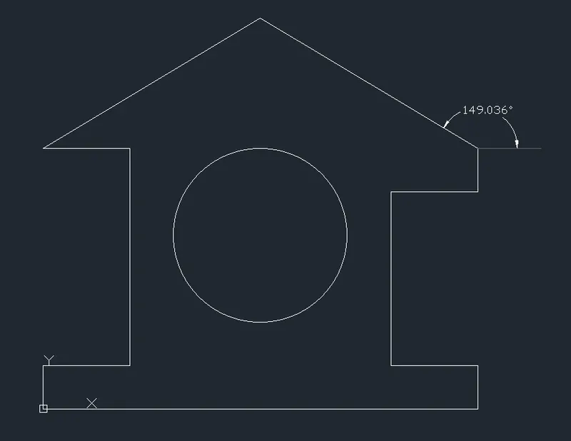
Drafted using Relative Polar Coordinates
- Start the AutoCAD software, use the Imperial Template and the Decimal Units to draft.
- Select Line to draw the orgin (0,0)
- Specify the next point (@10<0)
- Specify the next point (@1<90)
- Specify the next point (@2<180)
- Specify the next point (@4<90)
- Specify the next point (@2<0)
- Specify the next point (@1<90)
- Specify the next point (@5.831<149.036)
- Specify the next point (@5.831<-149.036)
- Specify the next point (@2<0)
- Specify the next point (@5<270)
- Specify the next point (@2<180)
- Then, the last point was Close command 'C' to point in the orgin (0,0)
- Then, select Circle to draw a circle of radius '2' at point (5,4)
Queen Post Truss
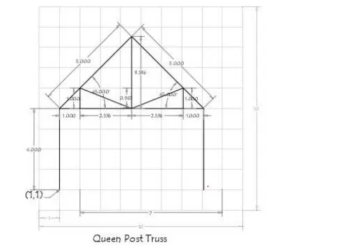
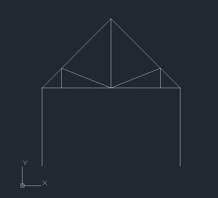
Drafted using Relative Polar Coordinates, Absolute Coordinates Systems
- Start the AutoCAD software, use the Imperial Template and the Decimal Units to draft.
- Select Line to draw the orgin (1,1)
- Specify the next point (@4<90)
- Specify the next point (@5<45)
- Specify the next point (@5<-45)
- Specify the next point (@4<270) and click exit 'E'.
- Then, select Line and draw line from (1,5) to (8.072,5) and click exit 'E'.
- Then, again select Line to draw another orgin (2,5)
- Specify the next point (2,5)
- Specify the next point (2,6)
- Specify the next point (4.536,5)
- Specify the next point (7.072,6)
- Specify the next point (7.072,5) and click exit 'E'.
- Then, again select Line and draw line from (4.536,5) to (4.536,8.536)
Mono Pitch
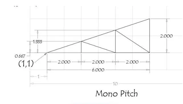
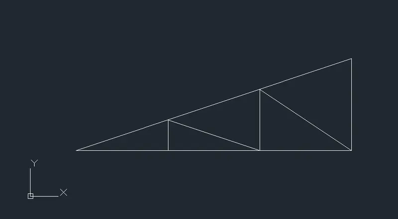
Drafted using Relative Rectangular Coordinates
- Start the AutoCAD software, use the Imperial Template and the Decimal Units to draft.
- Select Line to draw the orgin (1,1)
- Specify the next point (@6,0)
- Specify the next point (@0,2)
- Then, the last point of that polygon was Close command 'C' to point in the orgin (1,1)
- Then, select Line to draw the orgin (3,1)
- Specify the next point (@0,0.667)
- Specify the next point (@2,-0.667)
- Specify the next point (@0,1.333)
- Specify the next point (@2,-1.333) and click exit 'E'.
RESULTS
1. Created the geometries from P1 to P2 using all the coordinates system methods by line tool.
2. Created the geometries from P4, P5, P7, P8, P9, P10 using different coordinates system methods by line tool.
3. The profile and the trusses using different coordinate system methods were drafted using line and circle tool.