Creating a Floor plan, Footing detail and Isometric view using AutoCad
Question 1: C1
AIM
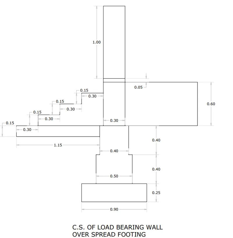
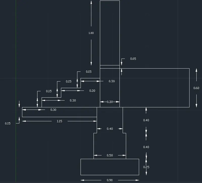
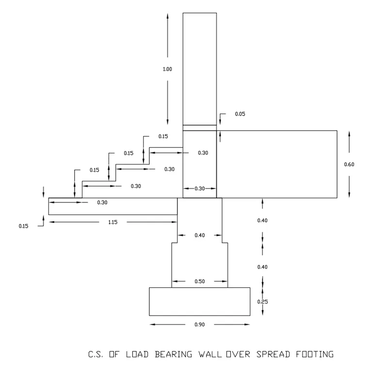
To draw the figure C1 of cross-section of load bearing wall over spread footing.
INTRODUCTION
A footing in building construction that is shallow in proportion to its width and is usually made of reinforced concrete. A load-bearing wall, also known as a bearing wall, is an active structural feature of a building that transfers the weight of the elements above it to a foundation structure below it.
PROCEDURE
To draw the cross-section of load bearing wall over spread footing, proper tools should be considered. Here LINE, RECTANGLE, MOVE, TRIM etc.. are used. The first step is to open AutoCAD and open a new drawing. Then, the step by step procedure is given below.
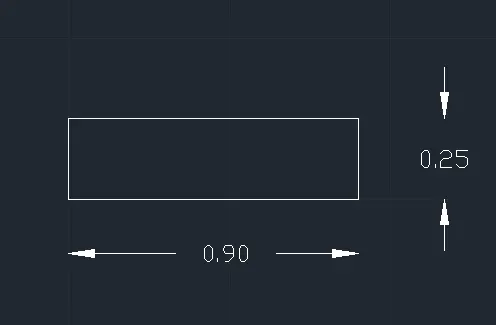
1. Type 'REC' in command line and select 'RECTANG'
- Specify first corner point: 1,1 (Assumed)
- Specify other corner point: @.9,0.25
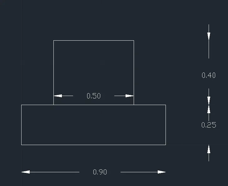
2. Type 'REC' in command line and select 'RECTANG'
- Specify first corner point: 1.2,1.25
- Specify other corner point: @0.5,0.4
3. Type 'REC' in command line and select 'RECTANG'
- Specify first corner point: 1.25,1.65
- Specify other corner point: @0.4,0.4
- Type 'TR' in command line and trim the unwanted portion
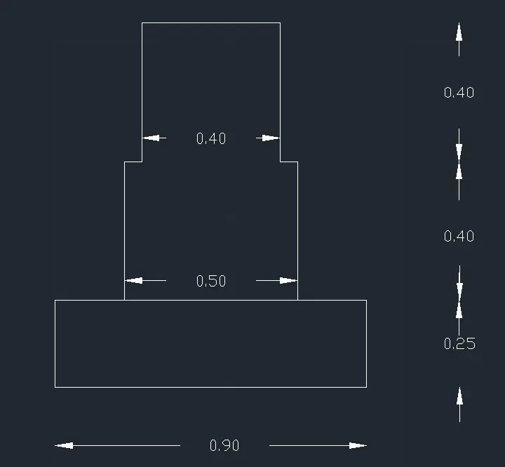
4. Type 'REC' in command line and select 'RECTANG'
- Specify first corner point: 1.3,2.05
- Specify other corner point: @0.3,0.6
- Extent the rectangle with the same height 0.6m
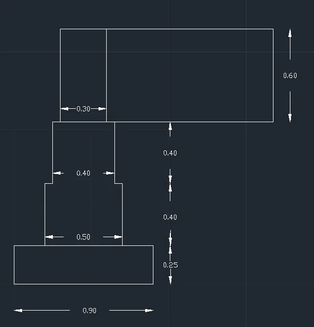
5. Type 'REC' in command line and select 'RECTANG'
- Specify first corner point: 1.3,2.65
- Specify other corner point: @0.3,0.05
- Extent the rectangle upto 1m as wall height
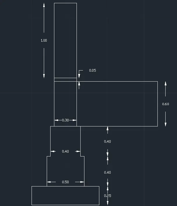
6. Type 'REC' in command line and select 'RECTANG'
- Specify first corner point: 1.25,2.05
- Specify other corner point: @-1.15,-0.15
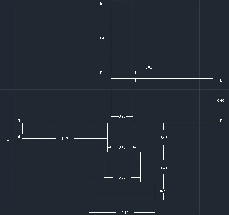
7. Type 'L' in command line and select 'LINE'
- Zero length line created at 0.10, 2.05
- Specify next point: @0.3<0
- Specify next point: @0.15<90
- Specify next point: @0.3<0
- Specify next point: @0.15<90
- Specify next point: @0.3<0
- Specify next point: @0.15<90
- Specify next point: @0.3<0
- Then exit
RESULT
The figure C1 of cross-section of load bearing wall over spread footing is drawn. All dimensions are in meters 'm'.
Question 2: C2
AIM
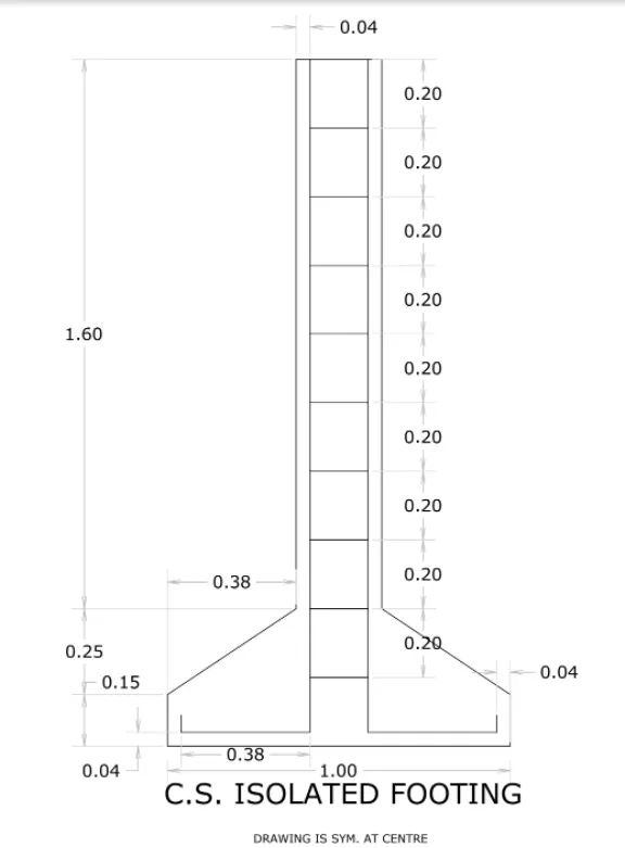
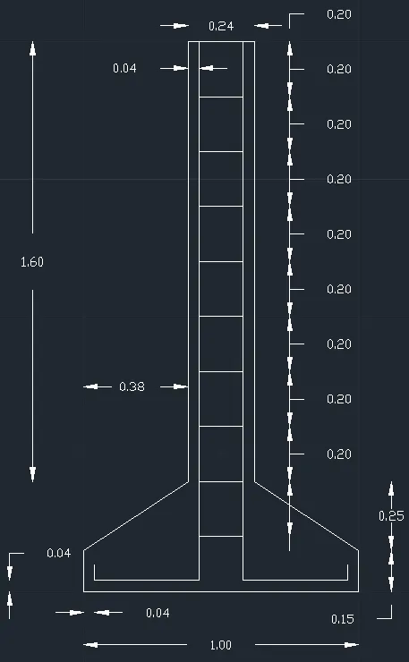
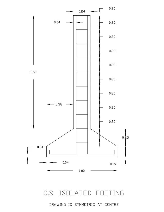
To draw the figure C2 of cross-section of isolated footing.
INTRODUCTION
Isolated footings (also known as Pad or Spread footings) are typically used for shallow foundations to carry and distribute concentrated loads such as those induced by columns or pillars. Material for isolated footings can be reinforced or non-reinforced.
PROCEDURE
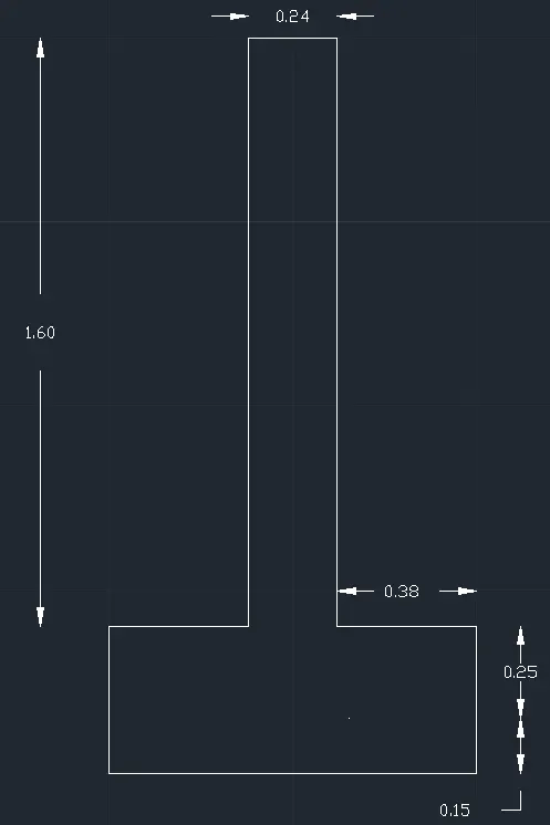
To draw the cross-section of isolated footing, proper tools should be considered. Here LINE, RECTANGLE, MOVE, TRIM, OFFSET, etc.. are used. The first step is to open AutoCAD and open a new drawing. Then, the step by step procedure is given below.
1. Type 'L' in command line and select 'LINE'
- Specify first corner point: 1,1 (Assumed)
- Specify next point: @1<0
- Specify next point: @0.15<90
- Specify next point: @0.25<90
- Specify next point: @0.38<180
- Specify next point: @1.6<90
- Specify next point: @0.24<180
- Specify next point: @1.6<270
- Specify next point: @0.38<180
- Specify next point: @0.25<270
- Specify next point: @0.15<270
2. Type 'L' in command line and select 'LINE'
- Specify first corner point: 2,1.15
- Specify next point: 1.62, 1.4
- This step is done for the other side
- Specify first corner point: 1,1.15
- Specify next point: 1.38, 1.4
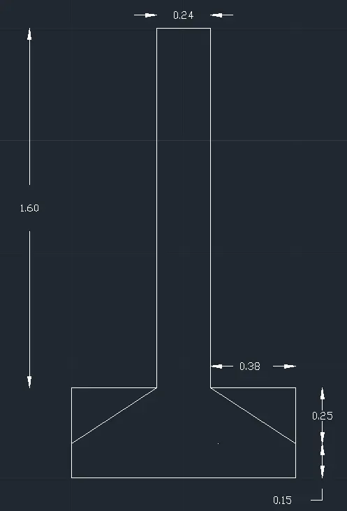
3. Type 'TR' and trim unnecessary lines
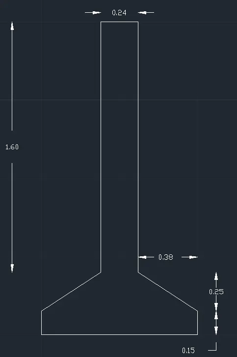
4. Type 'OFFSET' and offset essential lines
- Specify offset distance: 0.2
- Select object to offset
- Specify point on side to offset or [Exit/Multiple/Undo]: M
- Specify point on side to offset or [Exit/Undo]: next object until get the desired design
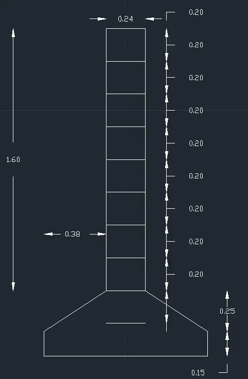
5. Type 'OFFSET' and offset essential lines
- Specify offset distance: 0.04
- Select object to offset
- Specify point on side to offset or [Exit/Multiple/Undo]: M
- Specify point on side to offset or [Exit/Undo]: next object until get the desired design
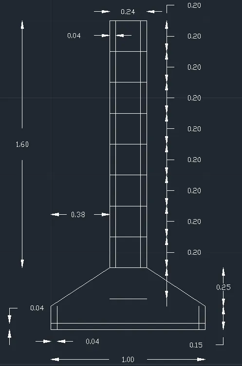
6. Trim, stretch, and reduce the lengths according to the design
RESULT
The figure C2 of cross-section of isolated footing is drawn. All dimensions are in meters 'm'.
Question 3: C3
AIM
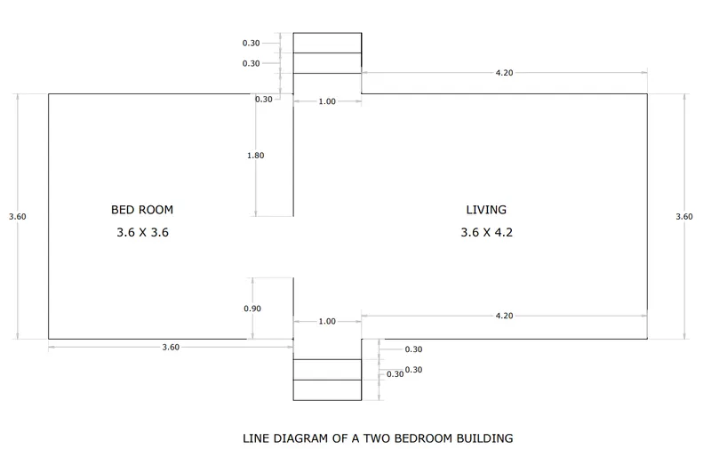
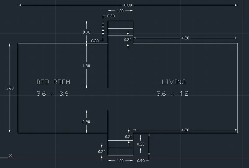
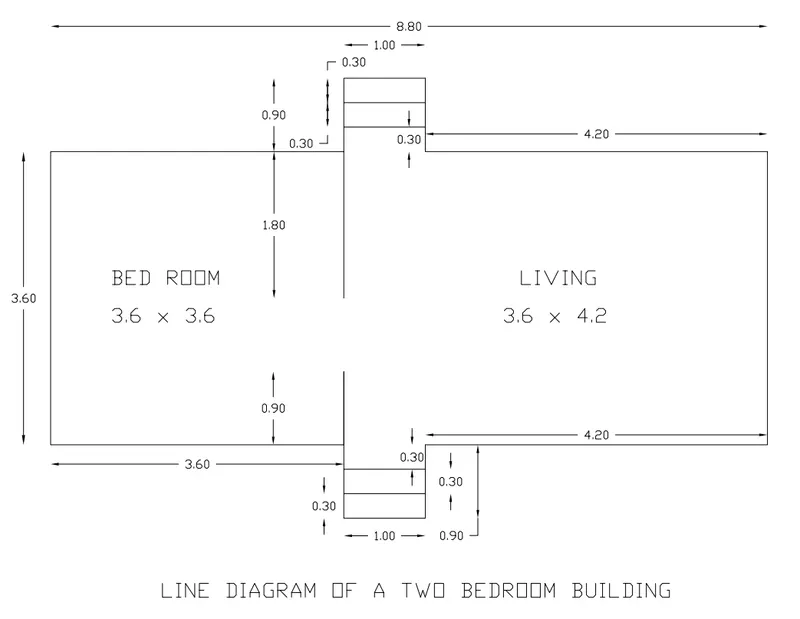
To draw the figure C3 of line diagram of a two bedroom building.
INTRODUCTION
In line diagram of a building, the position and size of internal rooms are given and the dimensions given are only internal ones that do not include wall thickness.
PROCEDURE
To draw the line diagram of a two bedroom building, proper tools should be considered. Here LINE, RECTANGLE, MOVE, TRIM, OFFSET, etc.. are used. The first step is to open AutoCAD and open a new drawing. Then, the step by step procedure is given below.
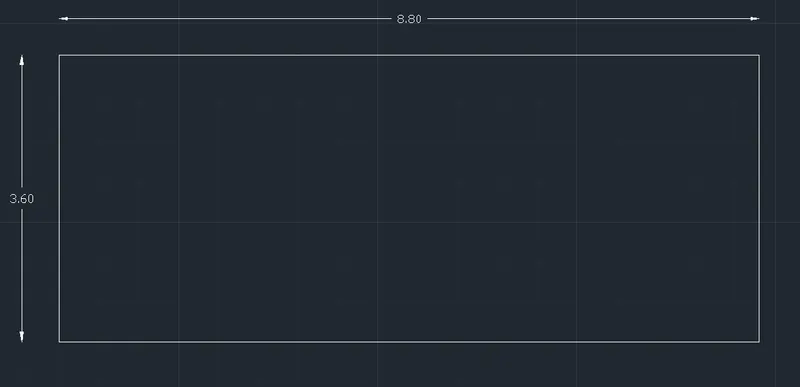
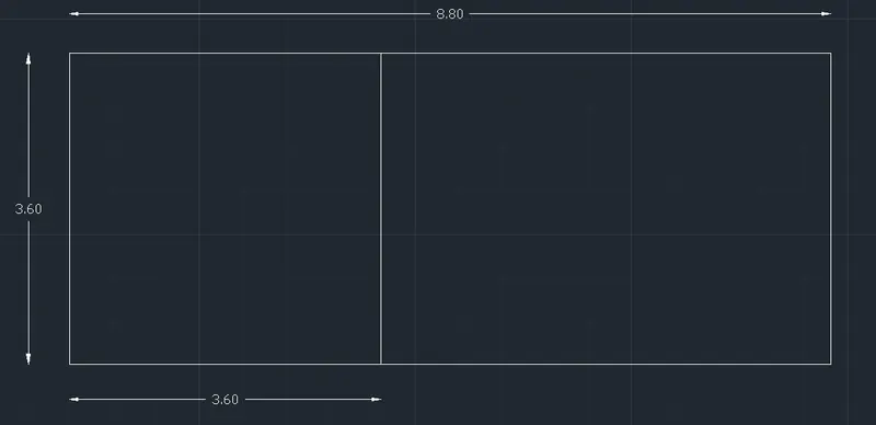
1. Type 'REC' in command line and select 'RECTANG'
- Specify first corner point: 1,1 (Assume)
- Specify other corner point: @8.8,3.6
2. Type 'L' in command line and select 'LINE'
- Specify first corner point: 4.6,1
- Specify next point: 4.6,4.6
3. Type 'L' in command line and select 'LINE'
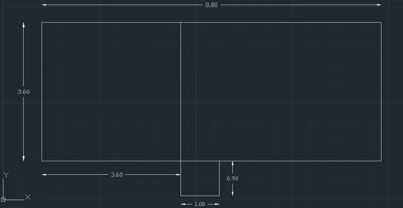
- Specify first corner point: 4.6,1
- Specify next point: @0.9<270
- Specify next point: @1<0
- Specify next point: @0.9<90
4. Type 'L' in command line and select 'LINE'
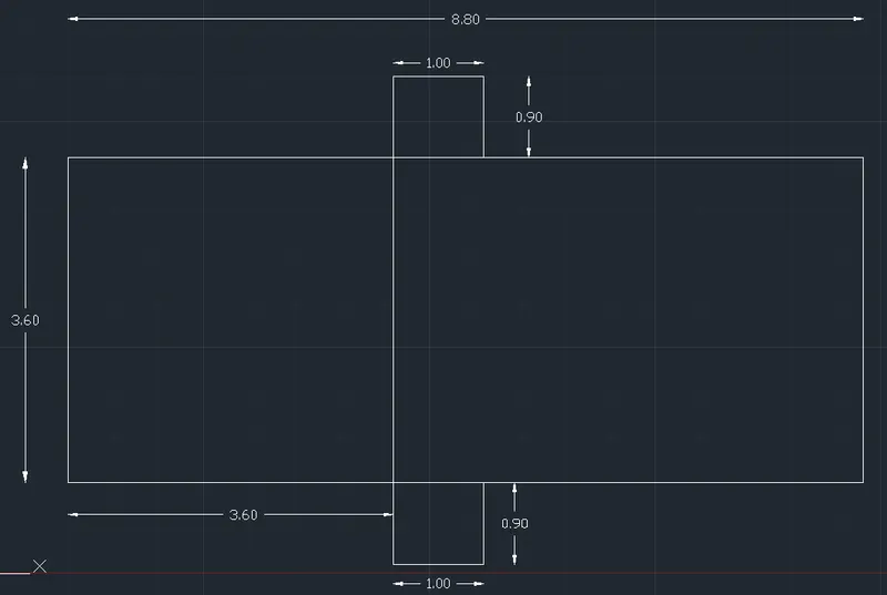
- Specify first corner point: 4.6,4.6
- Specify next point: @0.9<90
- Specify next point: @1<0
- Specify next point: @0.9<270
5. Type 'OFFSET' and offset essential lines
- Specify offset distance: 0.3
- Select object to offset
- Specify point on side to offset or [Exit/Multiple/Undo]: M
- Specify point on side to offset or [Exit/Undo]: next object until get the desired design
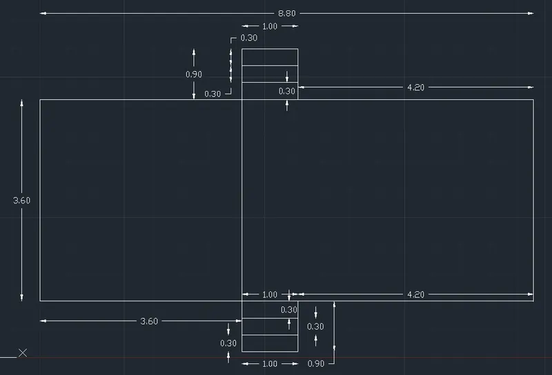
6. Type 'TR' and trim unnecessary lines and provide opening as shown in the figure by triming
RESULT
The figure C3 of line diagram of a two bedroom building is drawn. All dimensions are in meters 'm'.
Question 4: C4
AIM
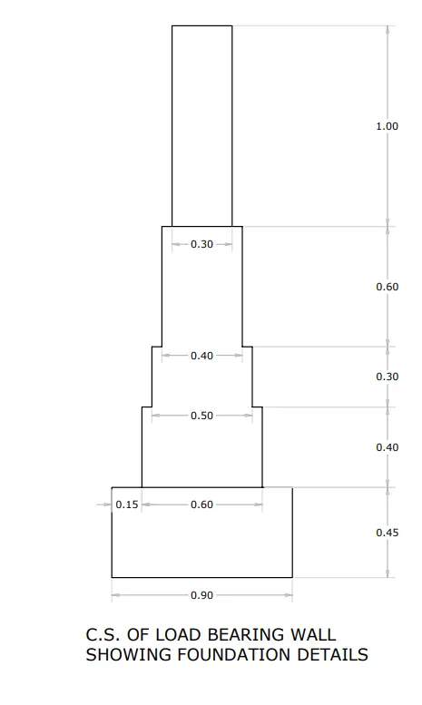
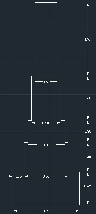
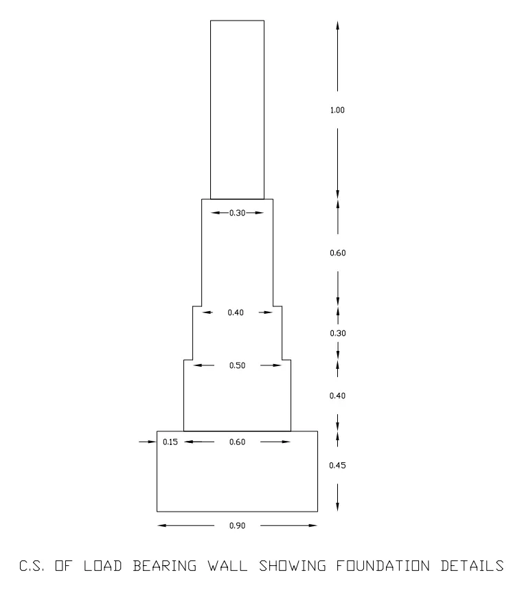
To draw the figure C3 of cross-section of load bearing wall showing foundation details.
INTRODUCTION
A footing in building construction that is shallow in proportion to its width and is usually made of reinforced concrete. A load-bearing wall, also known as a bearing wall, is an active structural feature of a building that transfers the weight of the elements above it to a foundation structure below it.
PROCEDURE
To draw the cross-section of load bearing wall, proper tools should be considered. Here LINE, RECTANGLE, MOVE, TRIM, OFFSET, etc.. are used. The first step is to open AutoCAD and open a new drawing. Then, the step by step procedure is given below.
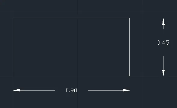
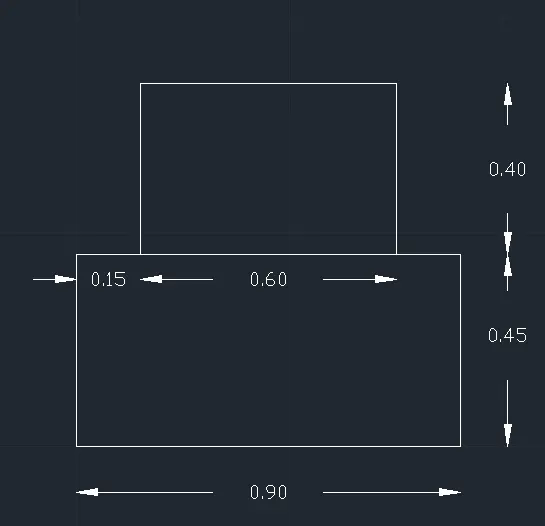
1. Type 'REC' in command line and select 'RECTANG'
- Specify first corner point: 1,1 (Assumed)
- Specify other corner point: @0.9,0.45
2. Type 'REC' in command line and select 'RECTANG'
- Specify first corner point: 1.15,1.45
- Specify other corner point: @0.6,0.4
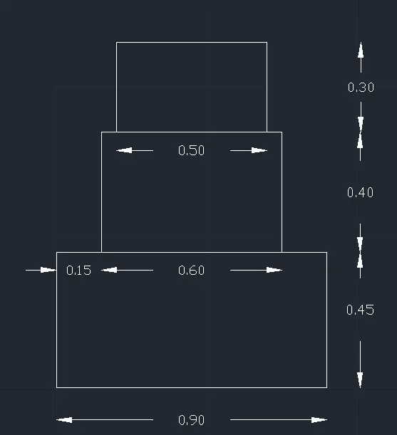
3. Type 'REC' in command line and select 'RECTANG'
- Specify first corner point: 1.2,1.85
- Specify other corner point: @0.5,0.3
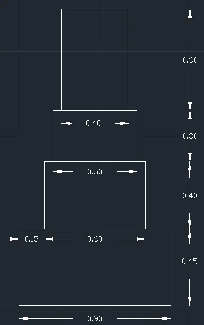
4. Type 'REC' in command line and select 'RECTANG'
- Specify first corner point: 1.25,2.15
- Specify other corner point: @0.4,0.6
5. Type 'REC' in command line and select 'RECTANG'
- Specify first corner point: 1.3,2.75
- Specify other corner point: @0.3,1
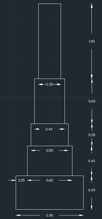
6. Type 'TR' and trim unnecessary lines
RESULT
The figure C3 of cross-section of load bearing wall showing foundation details is drawn. All dimensions are in meters 'm'.
Question 5: C5
AIM
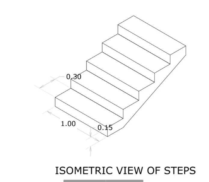
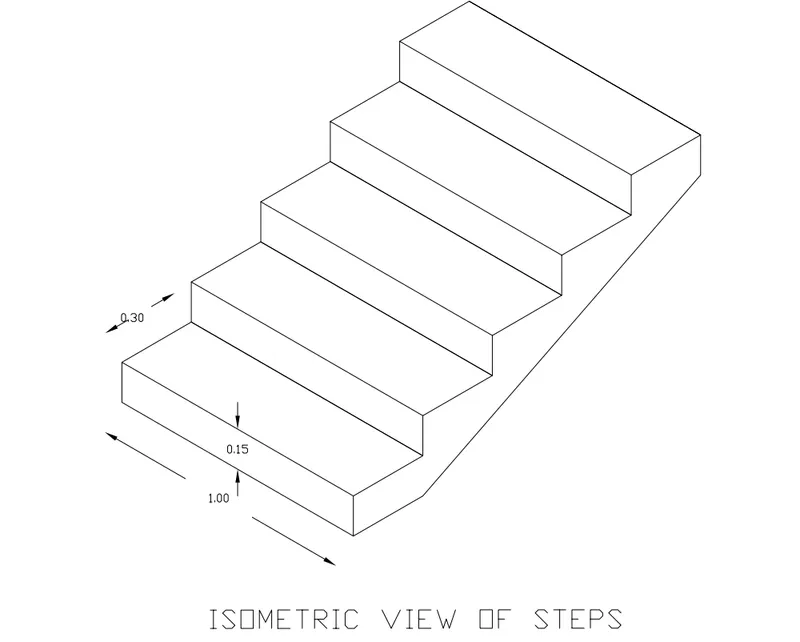
To draw the figure C5 of isometric view of steps.
INTRODUCTION
Isometric projection is a method for visually representing three-dimensional objects in two dimensions in technical and engineering drawings. A staircase or steps is the part of a building that helps us to move from one floor to another. It is a very important part of a building.
PROCEDURE
To draw the isometric view of steps, proper tools should be considered. Here LINE, COPY, MOVE, etc.. are used. The first step is to open AutoCAD and open a new drawing. Then, the step by step procedure is given below.
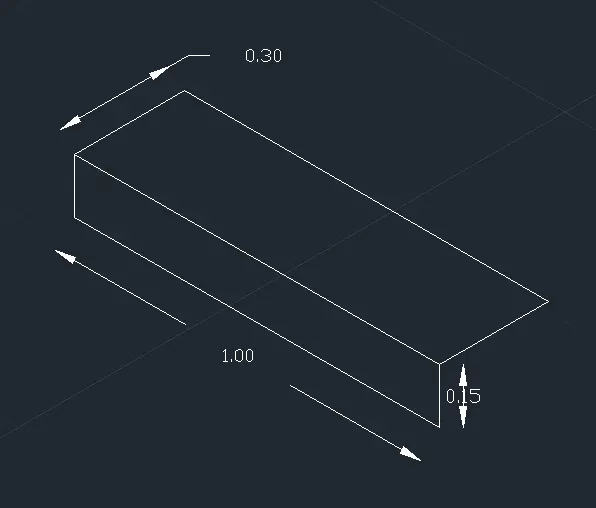
1. Type 'DS' to open Drafting Settings, and select 'Isometric snap' as snap type and then press 'OK'.
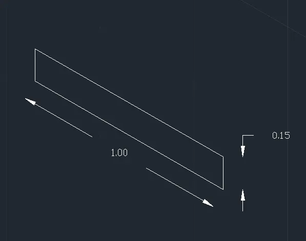
2. In isoplane left, Type 'L' in command line and select 'LINE'
- Specify first corner point: 1,1 (Assumed)
- Specify next point: 1
- Specify next point: 0.15
- Specify next point: 1
- Specify next point or [Close/eXit/Undo]: c
3. In isoplane top, Type 'L' in command line and select 'LINE'
- Specify first corner point: 1,1.15
- Specify next point: 0.3
- Specify next point: 1
- Specify next point: 0.3
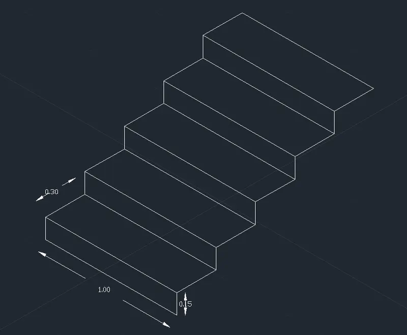
4. In isoplane top, Type 'CO' in command line and select 'COPY'
- Select objects: Select all the objects drawn
- Copy mode is applied as Multiple
- Specify base point: 1.26,1.3
- Specify second point or [Array] <use first point as displacement>: Copy according to the design
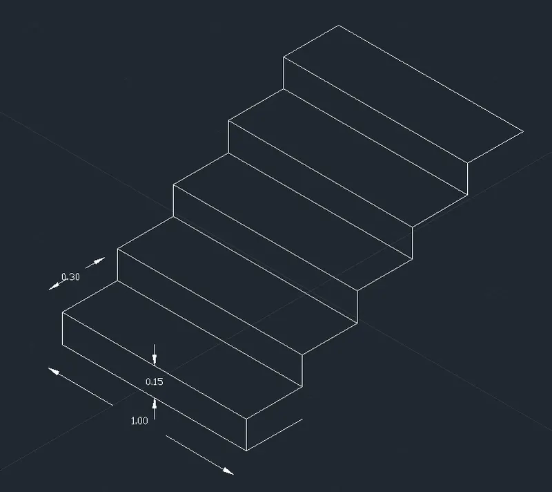
5. In isoplane top, Type 'L' in command line and select 'LINE'
- Specify first corner point: 1.87,0.5
- Specify next point: 0.3
6. In isoplane left, Type 'L' in command line and select 'LINE'
- Specify first corner point: 3.17,2
- Specify next point: 0.15
- Finally connect points (2.13,0.65) and (3.17,1.85) with the help of 'LINE'
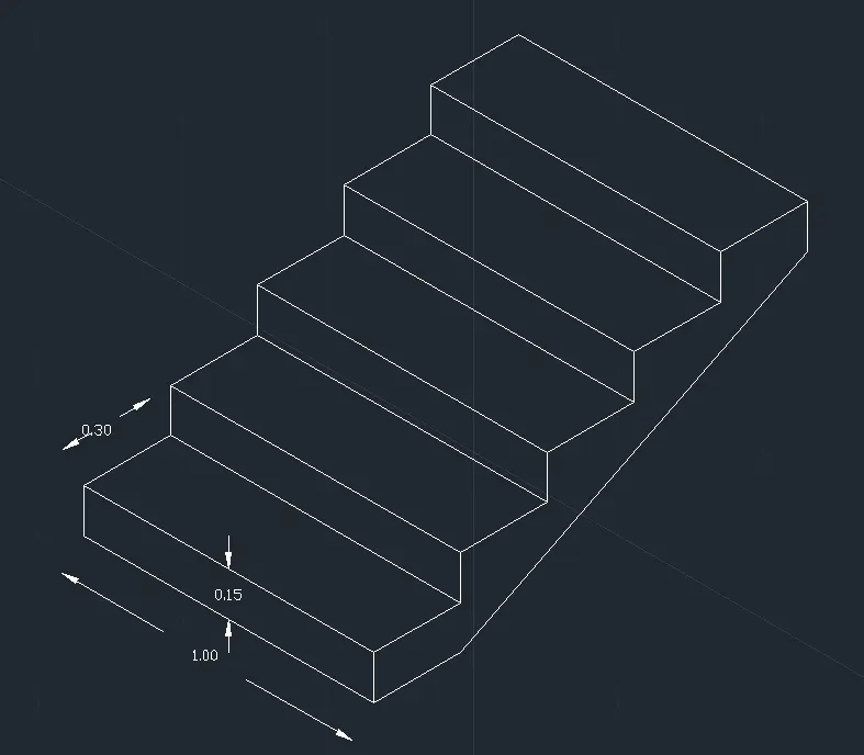
RESULT
The figure C5 of isometric view of steps is drawn. All dimensions are in meters 'm'. 'Ortho mode' was on for the entire process.
Question 6: C6
AIM
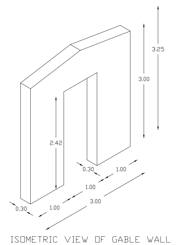
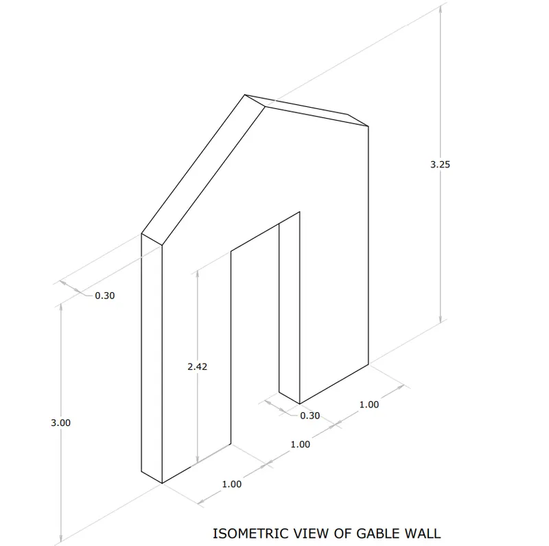
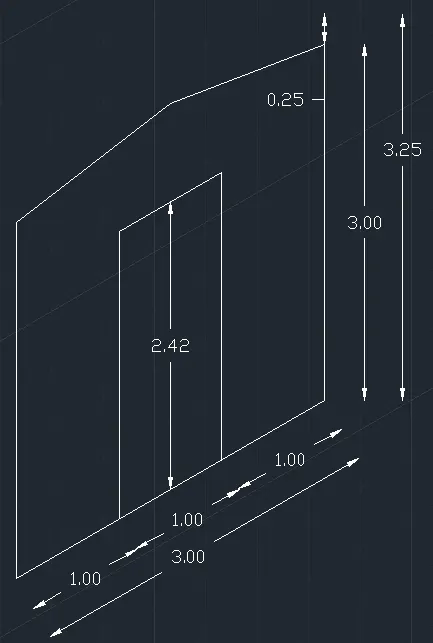
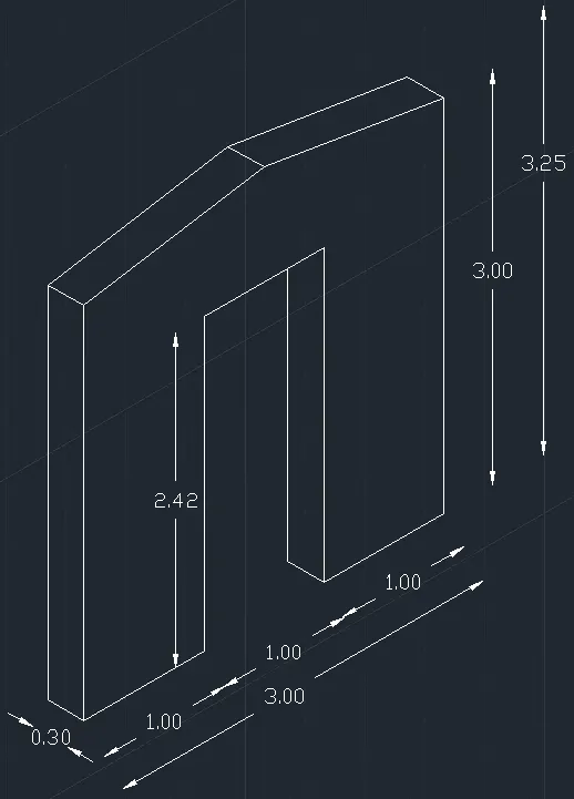
To draw the figure C6 of isometric view of gable wall.
INTRODUCTION
Isometric projection is a method for visually representing three-dimensional objects in two dimensions in technical and engineering drawings. A gable is the generally triangular portion of a wall between the edges of intersecting roof pitches. The shape of the gable and how it is detailed depends on the structural system used, which reflects climate, material availability, and aesthetic concerns.
PROCEDURE
To draw the isometric view of gable wall, proper tools should be considered. Here LINE, MOVE, COPY, TRIM, CHAMFER, etc.. are used. The first step is to open AutoCAD and open a new drawing. Then, the step by step procedure is given below.
1. Type 'DS' to open Drafting Settings, and select 'Isometric snap' as snap type and then press 'OK'.
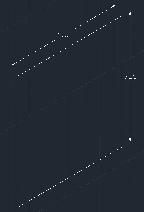
2. Type 'L' in command line and select 'LINE'
- Specify first corner point: 1,1 (Assumed)
- Specify next point: <Isoplane Right> 3
- Specify next point: <Isoplane Right> 3.25
- Specify next point: <Isoplane Right> 3
- Specify next point: c
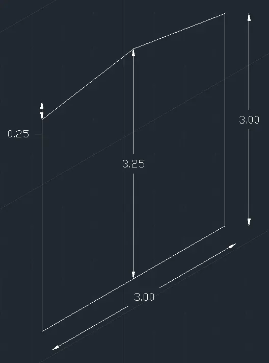
3. Type 'CHA' in command line and select 'CHAMFER'
- Select first line
- Specify first chamfer distance: 1.50
- Specify second chamfer distance: 0.25
- Select second line
- Do the same steps for the other side
4. Type 'L' in command line and select 'LINE'
- Specify first point: 1,1
- Specify next point: <Isoplane Right> 1
- Specify next point: <Isoplane Right> 2.42
- Specify next point: <Isoplane Right> 1
- Specify next point: <Isoplane Right> 2.42
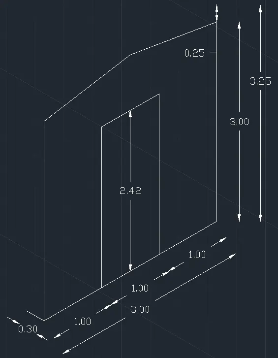
5. Type 'L' in command line and select 'LINE'
- Specify first point: 1,1
- Specify next point: <Isoplane Left> 0.3
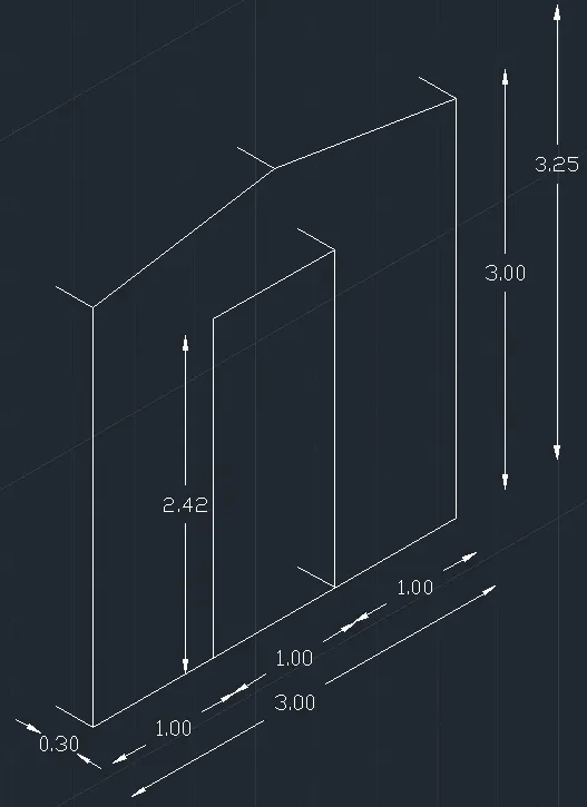
6. Type 'CO' in command line and select 'COPY'
- Select objects: Select the object drawn (0.3 line)
- Copy mode is applied as Multiple
- Specify base point: 1,1
- Specify second point or [Array] <use first point as displacement>: Copy according to the design
7. Type 'L' in command line and select 'LINE'
- Specify first point and connect all the line according to the design
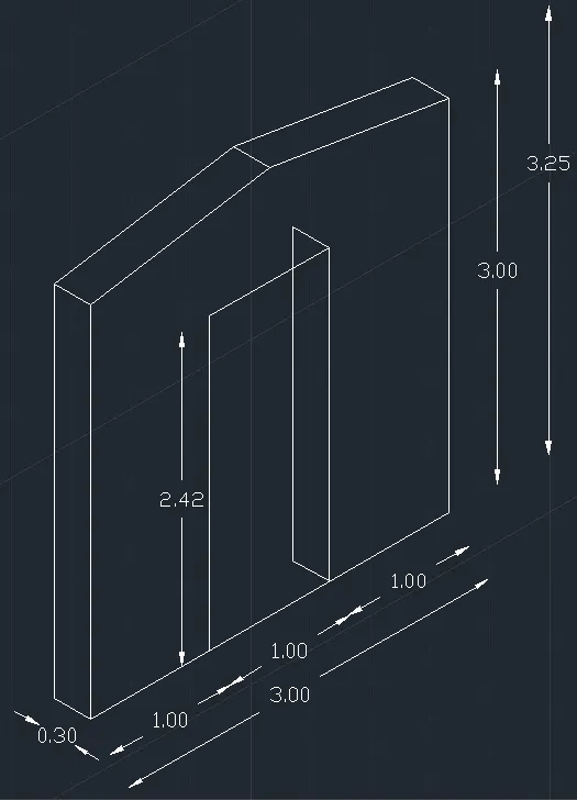
8. Type 'TR' and trim unnecessary lines
RESULT
The figure C6 of isometric view of gable wall is drawn. All dimensions are in meters 'm'. 'Ortho mode' was on for the entire process.