Drafting of various geometries using Chamfer, Fillet tool in AutoCad
AIM
Drafting of various geometries using different tools in AutoCAD.
INTRODUCTION
Create basic geometric objects such as lines, circles, and hatched areas. You can create a lot of different types of geometric objects in AutoCAD.
PROCEDURE
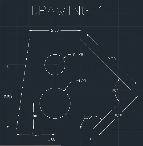
Drawing 1
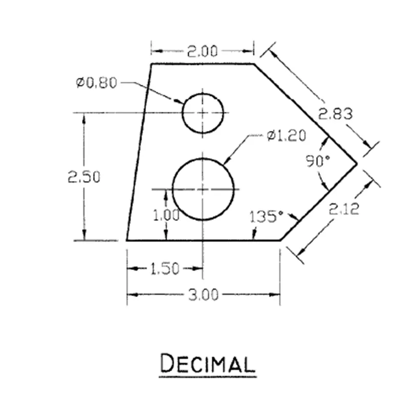
Before starting the drawing, change the length type to 'Decimal' and precision to '0.00"' in the 'Drawing Units'
1. Type 'L' in command line, and select 'LINE' tool
- Specify first point: 1,1
- Specify next point or [eXit/Undo]: @3<0
- Specify next point or [eXit/Undo]: @2.12<45
- Specify next point or [Close/eXit/Undo]: <Ortho on> 2.83
- Specify next point or [Close/eXit/Undo]: @2<180
- Specify next point or [Close/eXit/Undo]: c
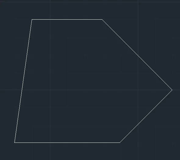
2. Type 'CIRCLE' in command line, and enter
- Specify center point for circle or [3P/2P/Ttr (tan tan radius)]: 2.5,2
- Specify radius of circle or [Diameter]: _d Specify diameter of circle: 1.2
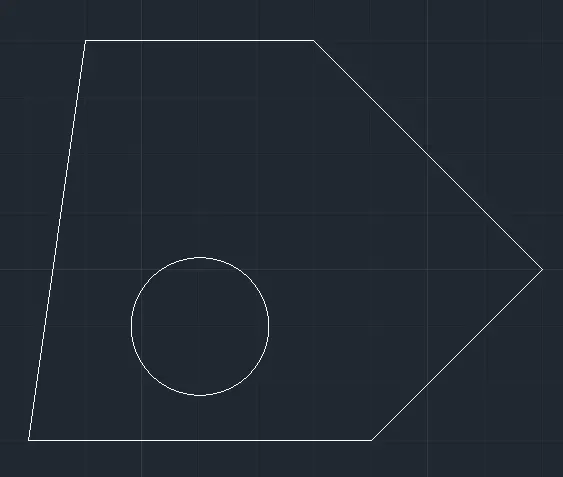
3. Type 'CIRCLE' in command line, and enter
- Specify center point for circle or [3P/2P/Ttr (tan tan radius)]: 2.5,3.5
- Specify radius of circle or [Diameter]: _d Specify diameter of circle: 0.8
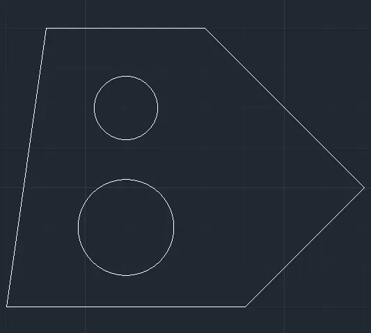
Final Result:
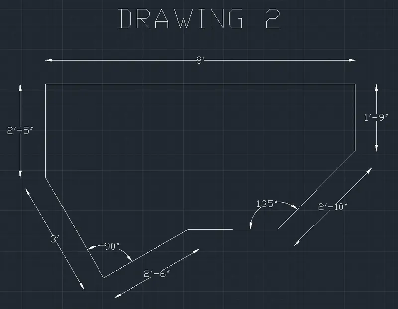
Drawing 2
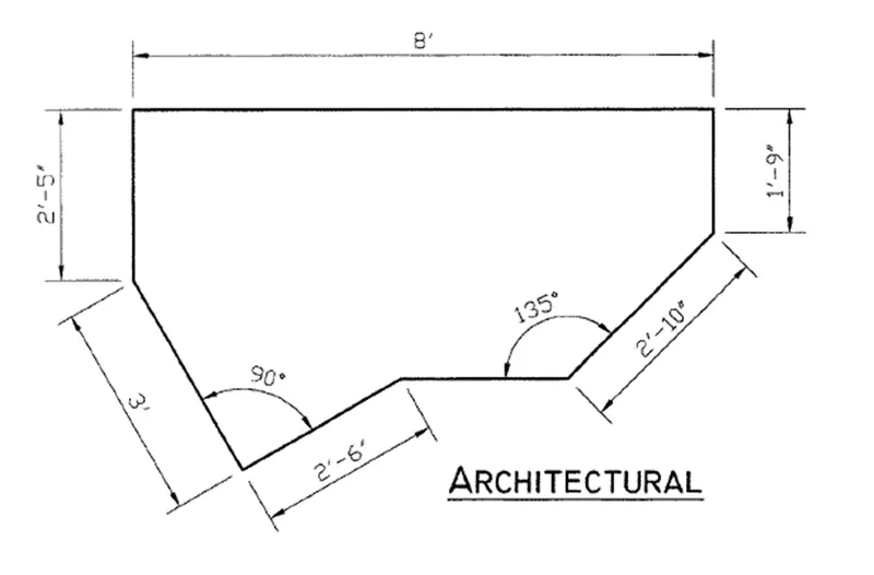
Before starting the drawing, change the length type to 'Architectural' and precision to '0-0"' in the 'Drawing Units'
1. Type 'L' in command line, and select 'LINE' tool
- Specify first point: 10',5' (Assumed)
- Specify next point or [Undo]: @2'5"<90
- Specify next point or [eXit/Undo]: 8'<0
- Specify next point or [Close/eXit/Undo]: 1'9"<270
- Specify next point or [Close/eXit/Undo]: @2'10"<-135
- Specify next point or [Close/eXit/Undo]: 3'<180
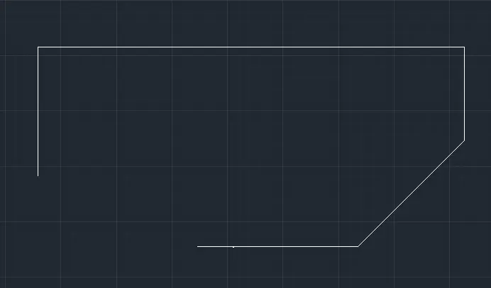
2. Type 'L' in command line, and select 'LINE' tool
- Specify first point: 10',5
- Specify next point or [Undo]: @3'<-60
- Specify next point or [eXit/Undo]: @2'6"<30
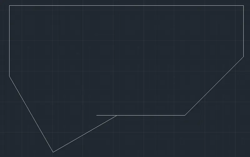
3. Type 'TR' in command line, and enter
- Trim the unnecessary lines according to the design
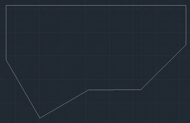
Final Result:
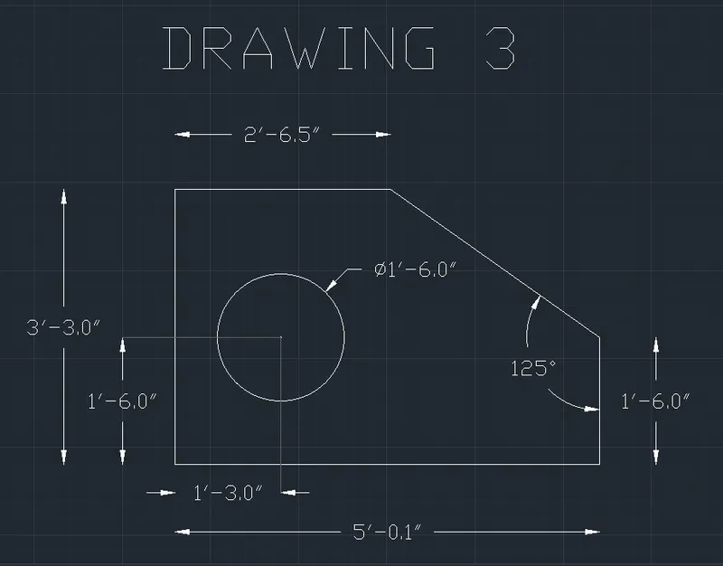
Drawing 3
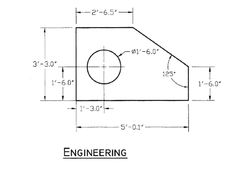
Before starting the drawing, change the length type to 'Engineering' and precision to '0-0.0"' in the 'Drawing Units'
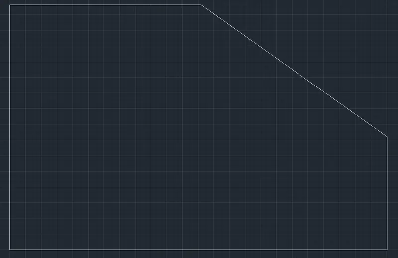
1. Type 'REC' in command line and select 'RECTANG'
- Specify first corner point or [Chamfer/Elevation/Fillet/Thickness/Width]: 10',5' (Assumed)
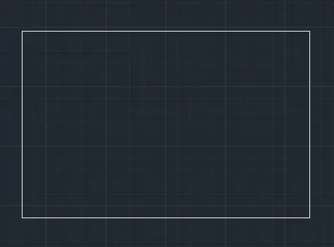
- Specify other corner point or [Area/Dimensions/Rotation]: @5'0.1",3'3"
2. Type 'CHA' in command line and select 'CHAMFER'
- Select first line
- Select second line or shift-select to apply corner or [Distance/Angle/Method]: d
- Specify first chamfer distance : 2'5.6"
- Specify second chamfer distance <2'-5.6">: 1'9"
- Select second line
3. Type 'C' in command line, and select 'CIRCLE'
- Specify center point for circle or [3P/2P/Ttr (tan tan radius)]: 11'3", 6'6"
- Specify radius of circle or [Diameter]: _d Specify diameter of circle: 1'6"
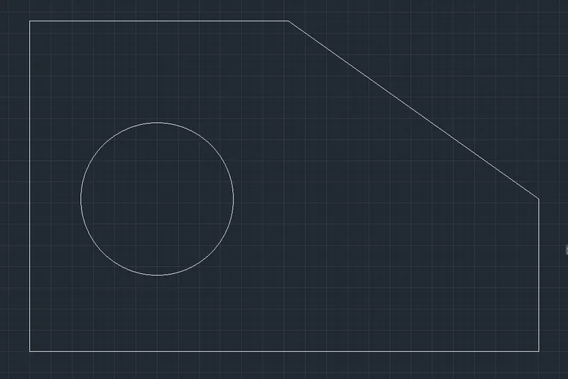
Final Result:
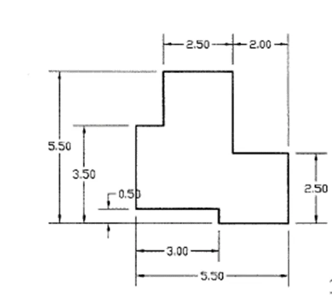
Drawing 4
Before starting the drawing, change the length type to 'Decimal' and precision to '0.00"' in the 'Drawing Units'
1. Type 'L' in command line, and select 'LINE' tool
- Specify first point: 1,1
- Specify next point or [Undo]: @3<0
- Specify next point or [eXit/Undo]: @0.5<270
- Specify next point or [Close/eXit/Undo]: @2.5<0
- Specify next point or [Close/eXit/Undo]: @2.5<90
- Specify next point or [Close/eXit/Undo]: @2<180
- Specify next point or [Close/eXit/Undo]: @3<90
- Specify next point or [Close/eXit/Undo]: @2.5<180
- Specify next point or [Close/eXit/Undo]: @2<270
- Specify next point or [Close/eXit/Undo]: @1<180
- Specify next point or [Close/eXit/Undo]: c
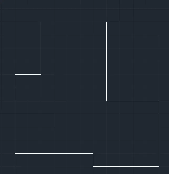
Final Result:
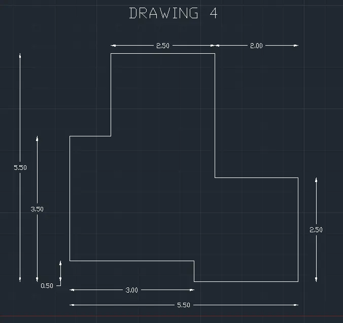
Drawing 5
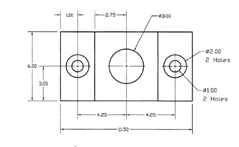
Before starting the drawing, change the length type to 'Decimal' and precision to '0.00"' in the 'Drawing Units'
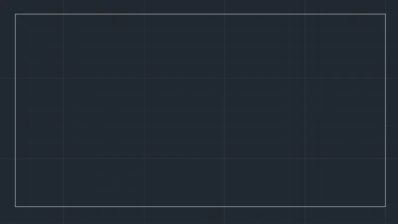
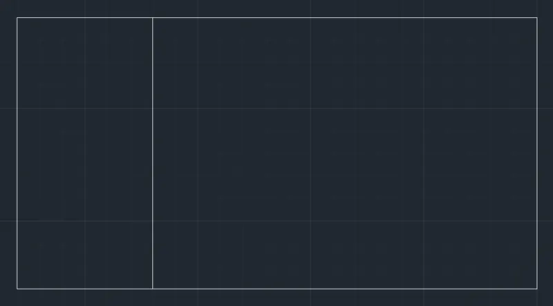
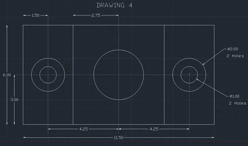
1. Type 'REC' in command line and select 'RECTANG'
- Specify first corner point or [Chamfer/Elevation/Fillet/Thickness/Width]: 1,1
- Specify other corner point or [Area/Dimensions/Rotation]: @11.5,6
2. Type 'L' in command line, and select 'LINE' tool
- Specify first point: 4,1
- Specify next point or [Undo]: @6<90
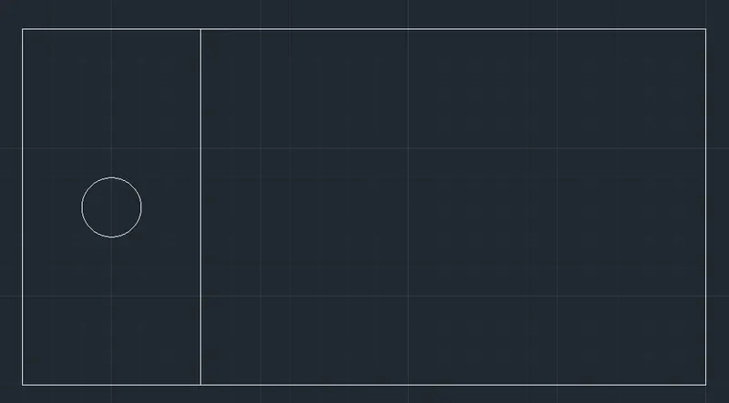
3. Type 'C' in command line, and select 'CIRCLE'
- Specify center point for circle or [3P/2P/Ttr (tan tan radius)]:2.5,4
- Specify radius of circle or [Diameter]: _d Specify diameter of circle: 1
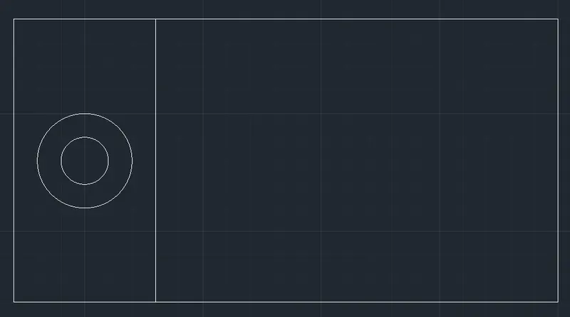
4. Type 'C' in command line, and select 'CIRCLE'
- Specify center point for circle or [3P/2P/Ttr (tan tan radius)]:2.5,4
- Specify radius of circle or [Diameter]: _d Specify diameter of circle <1.00>: 2
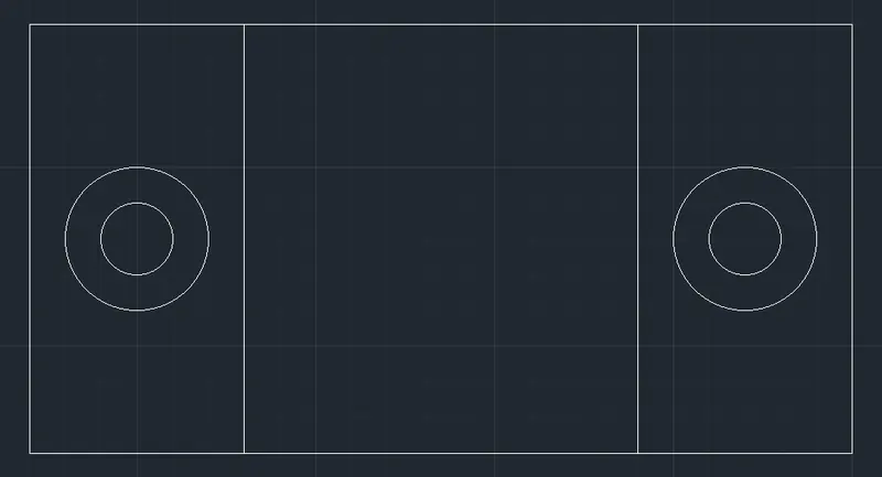
5. Type 'MI' in command line, and select 'MIRROR'
- Select objects tto mirror: 2 Circles and a line
- Specify first point of mirror line: Midpoint of the length of the rectangle on the upper side
- Specify second point of mirror line: Midpoint of the length of the rectangle on the lower side
- Erase source objects? [Yes/No] <No>: N
6. Type 'C' in command line, and select 'CIRCLE'
- Specify center point for circle or [3P/2P/Ttr (tan tan radius)]: 6.75,4
- Specify radius of circle or [Diameter]: _d Specify diameter of circle <2.00>: 3
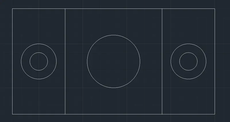
Final Result:
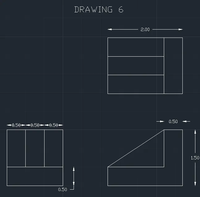
Drawing 6
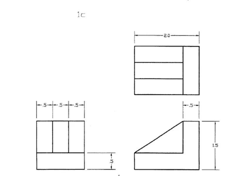
Before starting the drawing, change the length type to 'Decimal' and precision to '0.0"' in the 'Drawing Units'
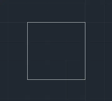
1. Type 'REC' in command line and select 'RECTANG'
- Specify first corner point or [Chamfer/Elevation/Fillet/Thickness/Width]: 1,1
- Specify other corner point or [Area/Dimensions/Rotation]: @1.5,1.5
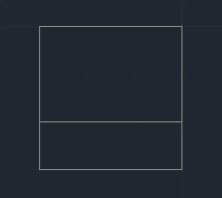
2. Type 'L' in command line, and select 'LINE' tool
- Specify first point: 1,1.5
- Specify next point or [Undo]: @1.5<0
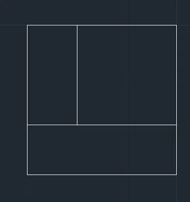
3. Type 'L' in command line, and select 'LINE' tool
- Specify first point: 1.5,1.5
- Specify next point or [Undo]: @1<90
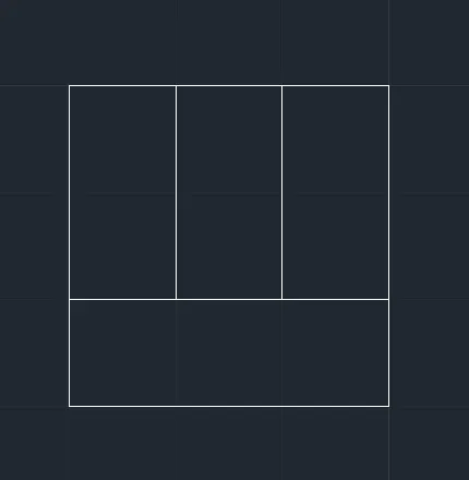
4. Type 'OFFSET' and enter
- Specify offset distance or [Through/Erase/Layer] <Through>: 0.5
- Select object to offset or [Exit/Undo] <Exit>:
- Specify point on side to offset or [Exit/Multiple/Undo] <Exit>:
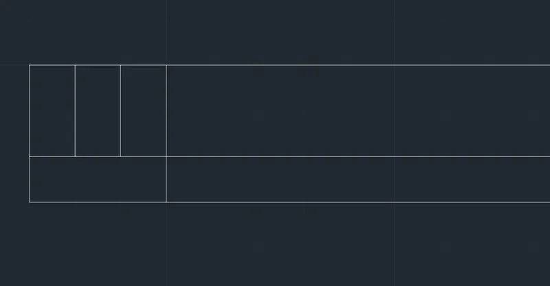
5. Type 'RAY' and enter
- Specify start point: Select the points where ray line should go according to the design
- Specify through point: Direction of ray
6. Type 'L' in command line, and select 'LINE' tool
- Specify first point: 5,1 (Assumed)
- Specify next point or [Undo]: 0.5<90
- Repeat LINE command
- Specify first point: 7,1
- Specify next point or [Undo]: @1.5<90
- Repeat LINE command
- Specify first point: 6.5,1.5
- Specify next point or [Undo]: @1<90
- Specify next point: 5,1.5
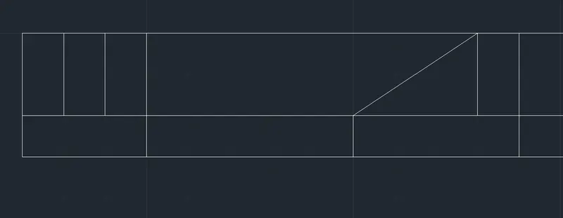
7. Type 'TR' and enter
- Trim the unnecessary lines according to the design
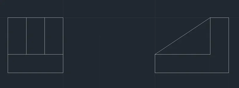
8. Type 'RAY' and enter
- Specify start point: Select the points where ray line should go according to the design
- Specify through point: Direction of ray
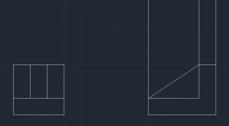
9. Type 'CO' and select 'COPY'
- Select objects: First figure drawn
- Specify base point or [Displacement/mOde] <Displacement>: 1,1
- Specify second point or [Array] <use first point as displacement>: any point in the upper direction
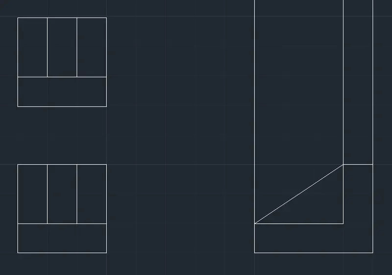
10. Type 'RAY' and enter
- Specify start point: Select the points where ray line should go according to the design
- Specify through point: Direction of ray
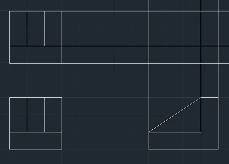
11. Type 'OFFSET' and enter
- Specify offset distance or [Through/Erase/Layer] <Through>: 0.5
- Select object to offset or [Exit/Undo] <Exit>:
- Specify point on side to offset or [Exit/Multiple/Undo] <Exit>:
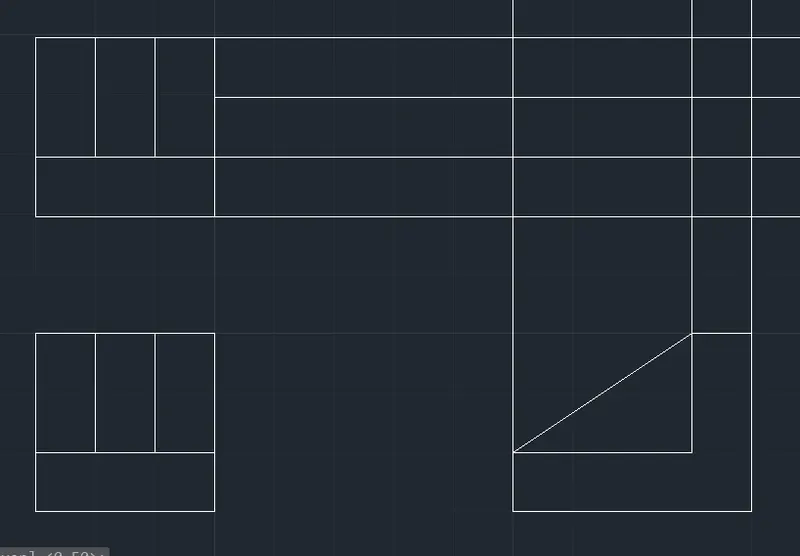
12. Type 'TR' and enter.
- Trim the unnecessary lines according to the design
- Erase unwanted objects using 'ERASE'
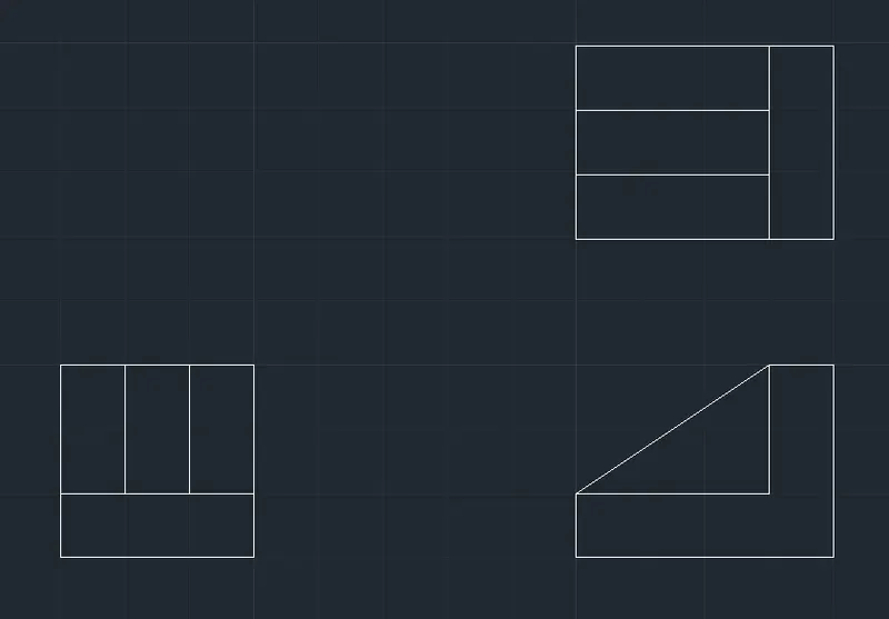
Final Result:
Drawing 7
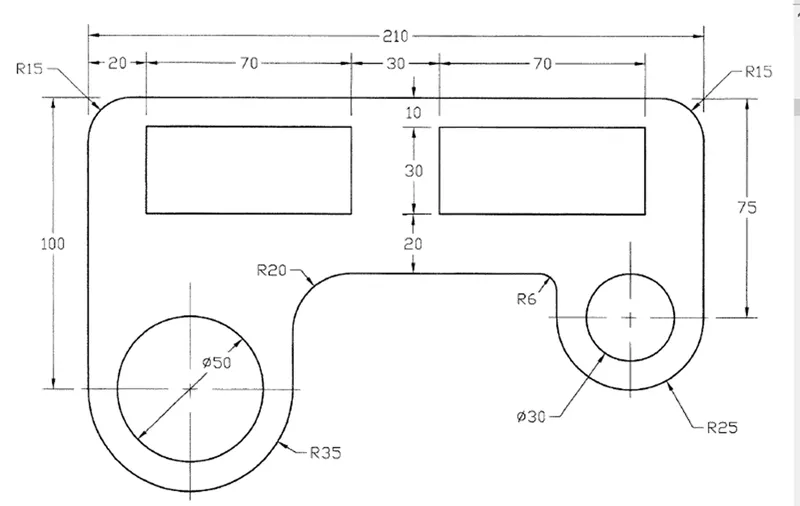
Before starting the drawing, change the length type to 'Decimal' and precision to '0' in the 'Drawing Units'
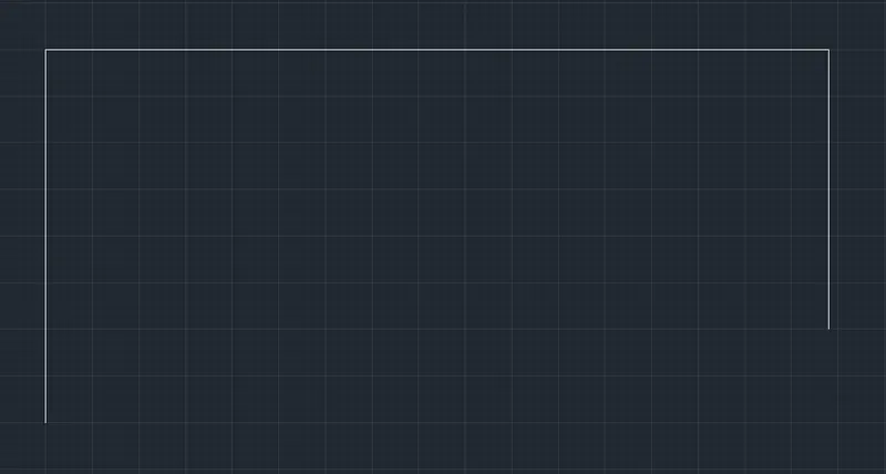
1. Type 'L' in command line, and select 'LINE' tool
- Specify first point: 50,50 (Assumed)
- Specify next point or [Undo]: 100
- Specify next point or [eXit/Undo]: 210
- Specify next point or [Close/eXit/Undo]: 75
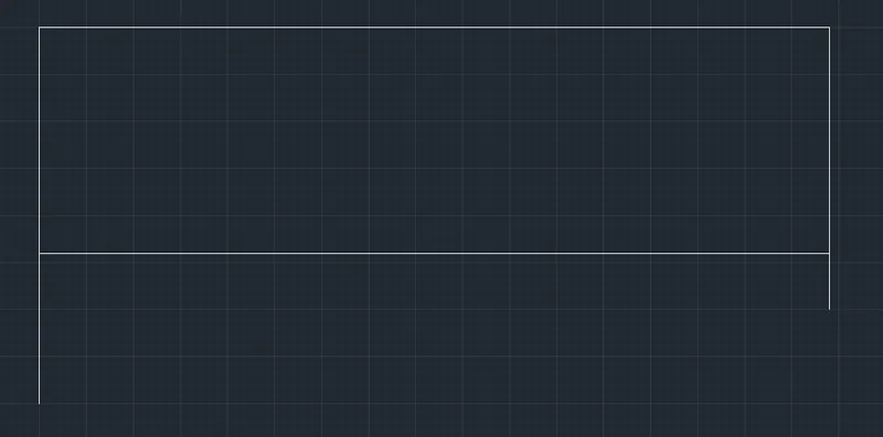
2. Type 'OFFSET' and enter
- Specify offset distance or [Through/Erase/Layer] <Through>: 60
- Select object to offset or [Exit/Undo] <Exit>:
- Specify point on side to offset or [Exit/Multiple/Undo] <Exit>:
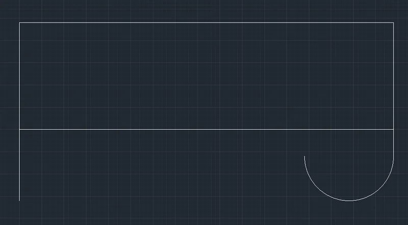
3. Type 'ARC' and enter
- Specify start point of arc or [Center]: select the right bottom corner point
- Specify second point of arc or [Center/End]: _e
- Specify end point of arc: @50<0
- Specify center point of arc (hold Ctrl to switch direction) or [Angle/Direction/Radius]: _r
- Specify radius of arc (hold Ctrl to switch direction): 25
4. Type 'ARC' and enter
- Specify start point of arc or [Center]: select the left bottom corner point
- Specify second point of arc or [Center/End]: _e
- Specify end point of arc: @70<0
- Specify center point of arc (hold Ctrl to switch direction) or [Angle/Direction/Radius]: _r
- Specify radius of arc (hold Ctrl to switch direction): 35
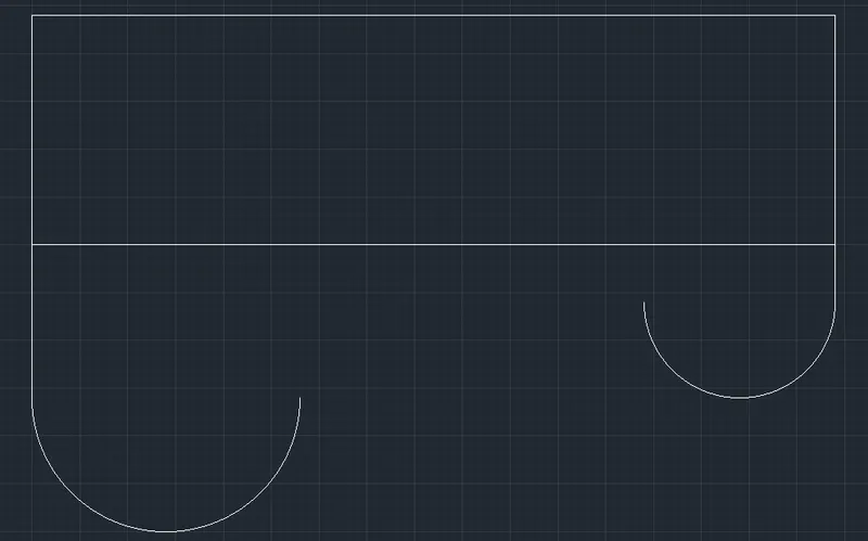
5. Using 'LINE', connect the one end of the arc perpendicular to the opposite line for both the arcs.
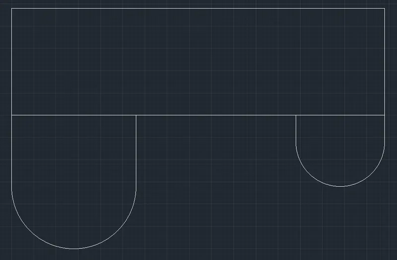
6. Trim the unnecassary lines using 'TR' in command line
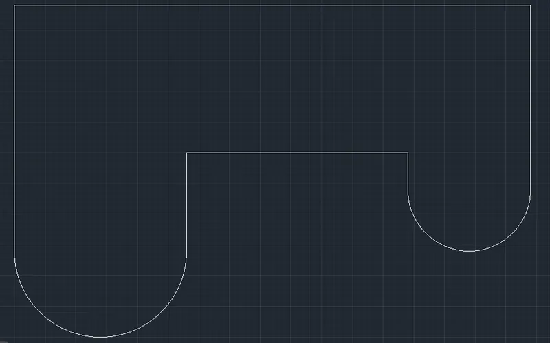
7. Type 'C' in command line, and select 'CIRCLE'
- Specify center point for circle or [3P/2P/Ttr (tan tan radius)]: Point the center of the arc at the left
- Specify radius of circle or [Diameter]: _d Specify diameter of circle: 50
- Repeat 'C' in command line
- Specify center point for circle or [3P/2P/Ttr (tan tan radius)]: Point the center of the arc at the right
- Specify radius of circle or [Diameter]: _d Specify diameter of circle: 30
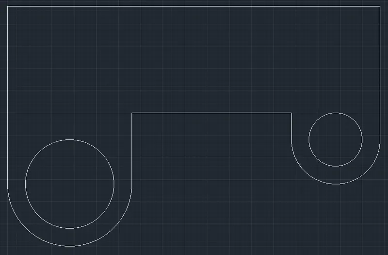
8. Type 'REC' in command line and select 'RECTANG'
- Specify first corner point or [Chamfer/Elevation/Fillet/Thickness/Width]: 70,145
- Specify other corner point or [Area/Dimensions/Rotation]: @70,30
- Repeat 'REC' in command line
- Specify first corner point or [Chamfer/Elevation/Fillet/Thickness/Width]: 170,145
- Specify other corner point or [Area/Dimensions/Rotation]: @70,30
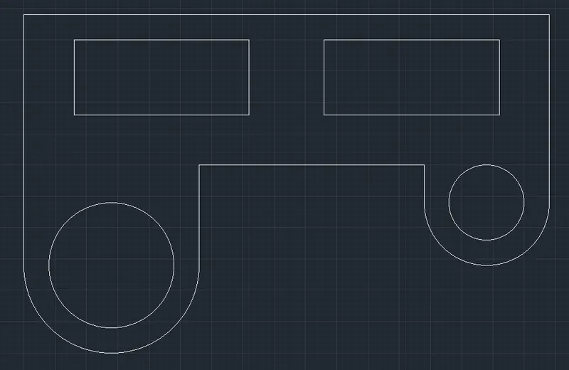
9. Type 'F' and select 'FILLET'
- Select first object or [Undo/Polyline/Radius/Trim/Multiple]: M
- Select first object or [Undo/Polyline/Radius/Trim/Multiple]:
- Select second object or shift-select to apply corner or [Radius]: r
- Specify fillet radius <20>: 15
- Select second object or shift-select to apply corner or [Radius]:
- Select first object or [Undo/Polyline/Radius/Trim/Multiple]:
- Select second object or shift-select to apply corner or [Radius]: r
- Specify fillet radius <15>:
- Select second object or shift-select to apply corner or [Radius]:
- Select first object or [Undo/Polyline/Radius/Trim/Multiple]:
- Select second object or shift-select to apply corner or [Radius]: r
- Specify fillet radius <15>: 6
- Select second object or shift-select to apply corner or [Radius]:
- Select first object or [Undo/Polyline/Radius/Trim/Multiple]:
- Select second object or shift-select to apply corner or [Radius]: r
- Specify fillet radius <6>: 20
- Select second object or shift-select to apply corner or [Radius]:
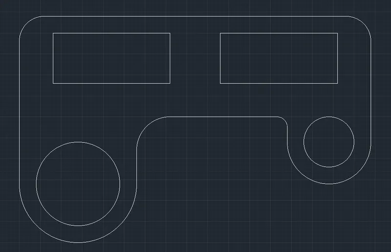
Final Result:
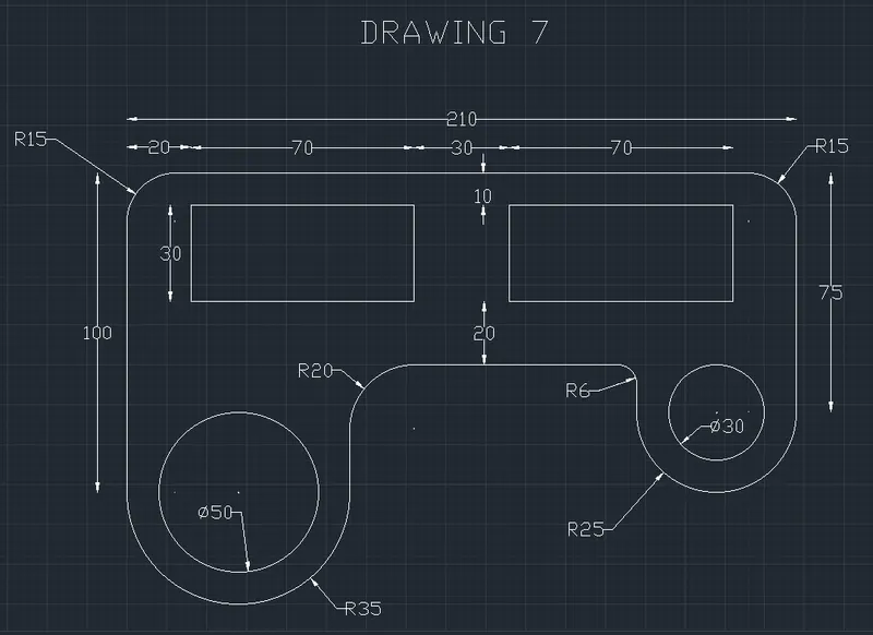
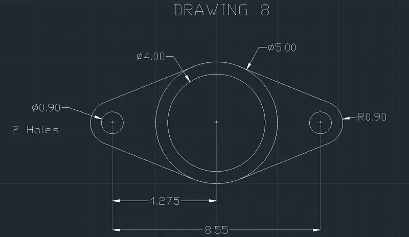
Drawing 8
Before starting the drawing, change the length type to 'Decimal' and precision to '0.000' in the 'Drawing Units'
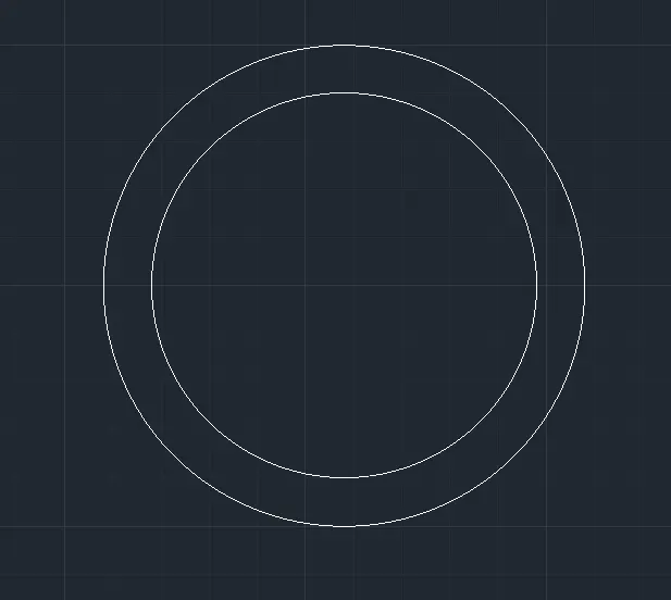
1. Type 'C' in command line, and select 'CIRCLE'
- Specify center point for circle or [3P/2P/Ttr (tan tan radius)]: 10,10 (Assumed)
- Specify radius of circle or [Diameter]: _d Specify diameter of circle: 4
- Repeat 'C' in command line, and select 'CIRCLE'
- Specify center point for circle or [3P/2P/Ttr (tan tan radius)]: 10,10
- Specify radius of circle or [Diameter]: _d Specify diameter of circle: 5
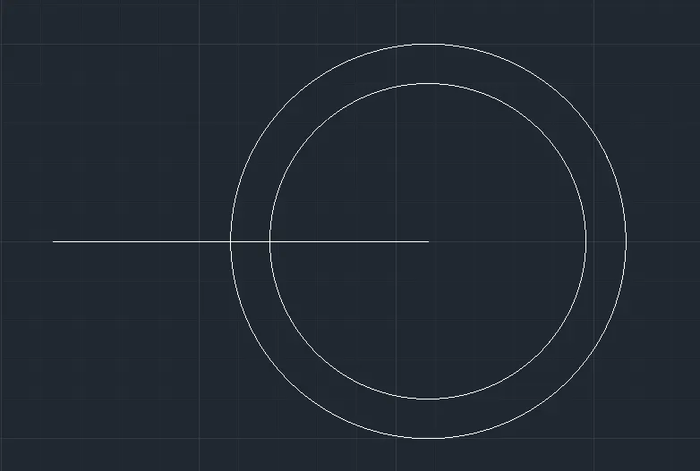
2. Type 'L' in command line, and select 'LINE' tool
- Specify first point: 10,10
- Specify next point or [Undo]: @4.275<180
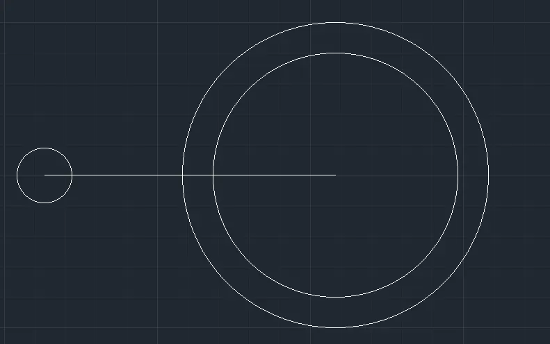
3. Type 'C' in command line, and select 'CIRCLE'
- Specify center point for circle or [3P/2P/Ttr (tan tan radius)]: 4.75 from (10,10)
- Specify radius of circle or [Diameter]: _d Specify diameter of circle: 0.9
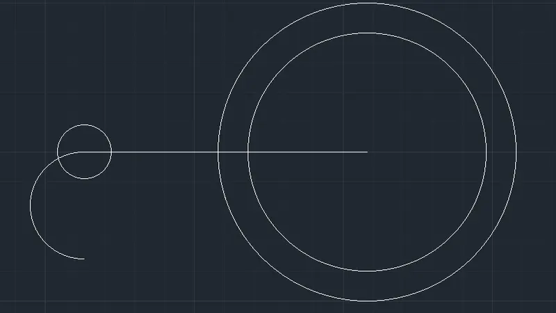
4. Type 'ARC' and enter
- Specify start point of arc or [Center]: Centre of the circle (diameter 0.9)
- Specify second point of arc or [Center/End]: _c
- Specify center point of arc: 0.9
5. Type 'M' and select 'MOVE'
- Select objects: Select the arc
- Specify base point or [Displacement] <Displacement>: Center of the arc
- Specify second point or <use first point as displacement>: Center of the circle (diameter 0.9)
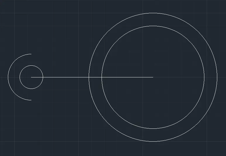
6. Use 'LINE' tool to connect the tangent of the arc and tangent of the circle (diameter 5)
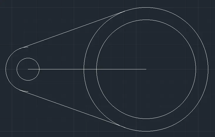
7. Trim unnecessary lines using 'TR' in command line
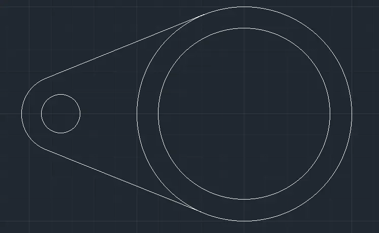
8. Type 'MI' and select 'MIRROR'
- Select objects: Specify opposite corner: 4 found
- Specify first point of mirror line:
- Specify second point of mirror line:
- Erase source objects? [Yes/No] <No>: N
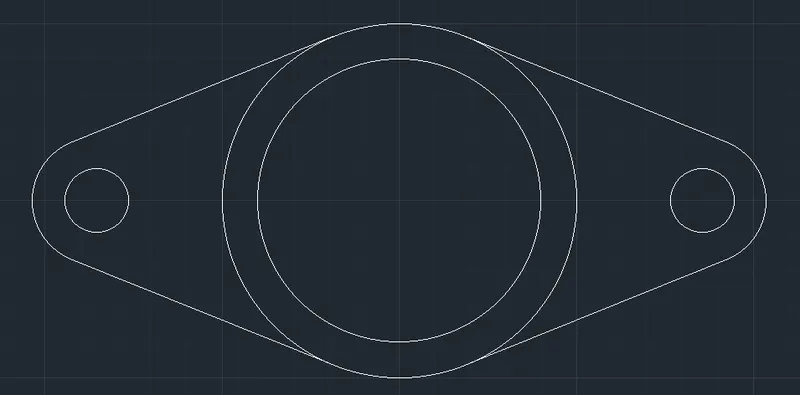
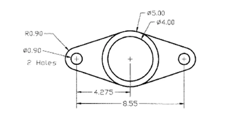
Final Result:
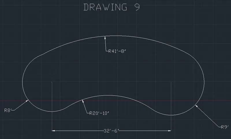
Drawing 9
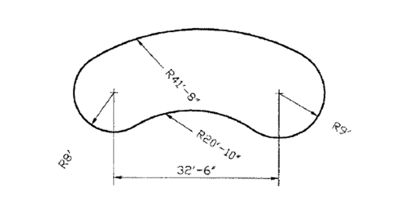
Before starting the drawing, change the length type to 'Engineering' and precision to '0'-0"' in the 'Drawing Units'
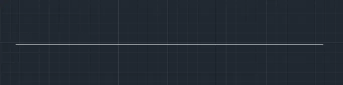
1. Type 'L' in command line, and select 'LINE' tool
- Specify first point: 10',5' (Assumed)
- Specify next point or [Undo]: @32'6"<180
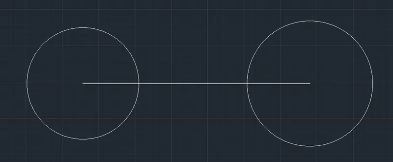
2. Type 'C' in command line, and select 'CIRCLE'
- Specify center point for circle or [3P/2P/Ttr (tan tan radius)]: 10',5'
- Specify radius of circle or [Diameter]: 8'
- Repeat 'C' in command line, and select 'CIRCLE'
- Specify center point for circle or [3P/2P/Ttr (tan tan radius)]: 42'6",5'
- Specify radius of circle or [Diameter]: 9'
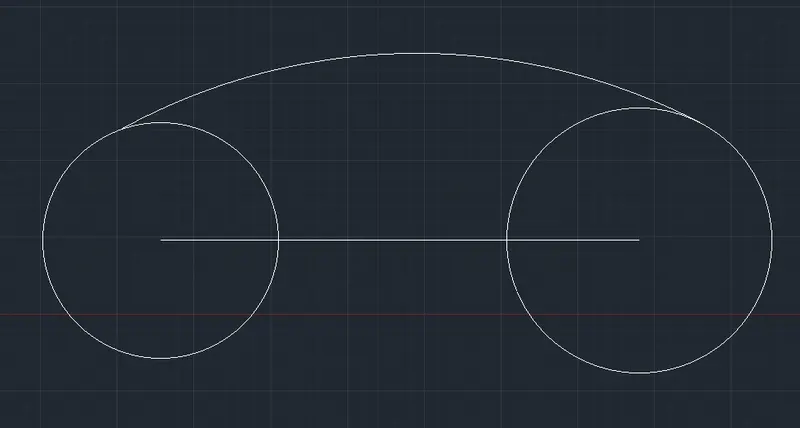
3. Type 'ARC' and enter
- Specify start point of arc or [Center]: Tangent from the circle (Diameter 9')
- Specify end point of arc: Tangent from the circle (Diameter 8')
- Specify center point of arc (hold Ctrl to switch direction) or [Angle/Direction/Radius]: _r
- Specify radius of arc (hold Ctrl to switch direction): 41'8"
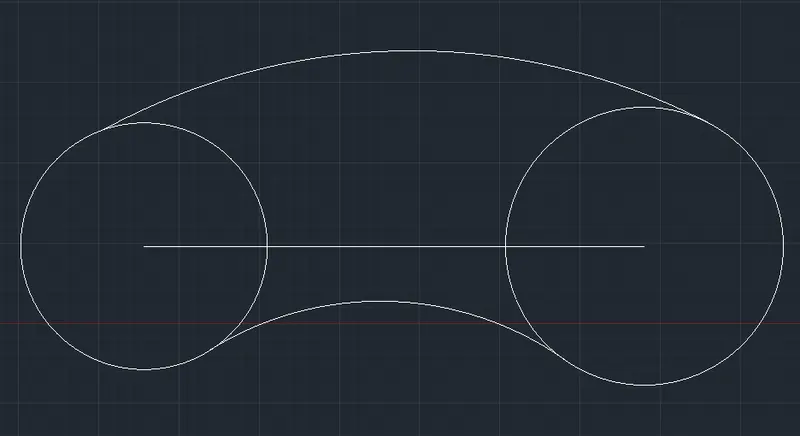
4. Type 'F' and select 'FILLET'
- Select first object or [Undo/Polyline/Radius/Trim/Multiple]: Select the circle (Diameter 9')
- Select second object or shift-select to apply corner or [Radius]: r
- Specify fillet radius: 20'10"
- Select second object or shift-select to apply corner or [Radius]: Select the circle (Diameter 8')
5. Trim unnecessary lines using 'TRIM' tool
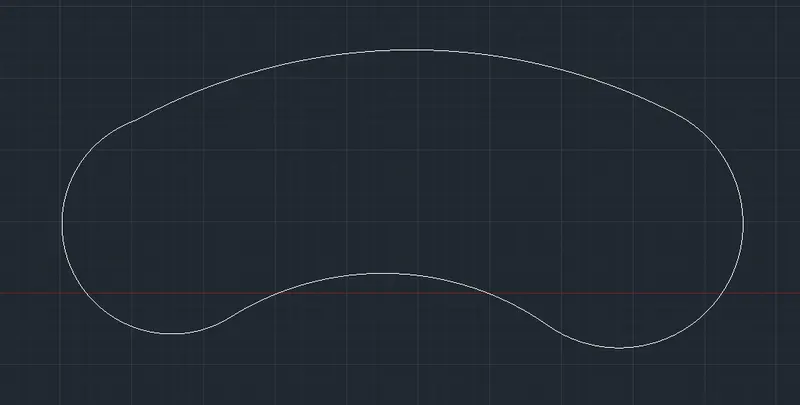
Final Result:
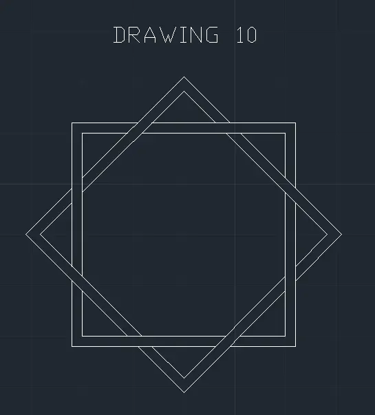
Drawing 10
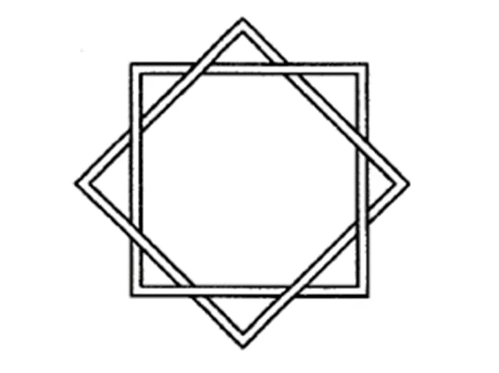
Before starting the drawing, change the length type to 'Decimal' and precision to '0' in the 'Drawing Units'
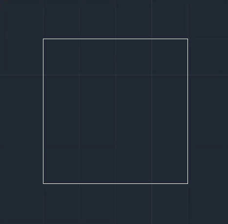
1. Type 'REC' in command line and select 'RECTANG'
- Specify first corner point or [Chamfer/Elevation/Fillet/Thickness/Width]: 1,1 (Assumed)
- Specify other corner point or [Area/Dimensions/Rotation]: @2,2
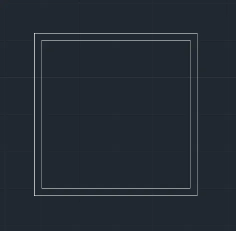
2. Type 'OFFSET' and enter
- Specify offset distance or [Through/Erase/Layer] <Through>: 0.1
- Select object to offset or [Exit/Undo] <Exit>:
- Specify point on side to offset or [Exit/Multiple/Undo] <Exit>:
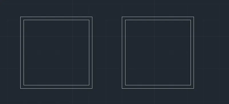
3. Type 'CO' and select 'COPY'
Specify base point or [Displacement/mOde] <Displacement>: 1,1
Specify second point or [Array] <use first point as displacement>:
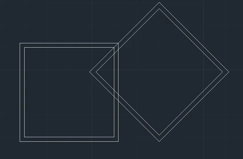
4. Type 'RO' in command line and select 'ROTATE'
- Select the objects: Select the copied objects
- Specify base point: Select the orgin of copied square
- Specify rotation angle or [Copy/Reference]: 45
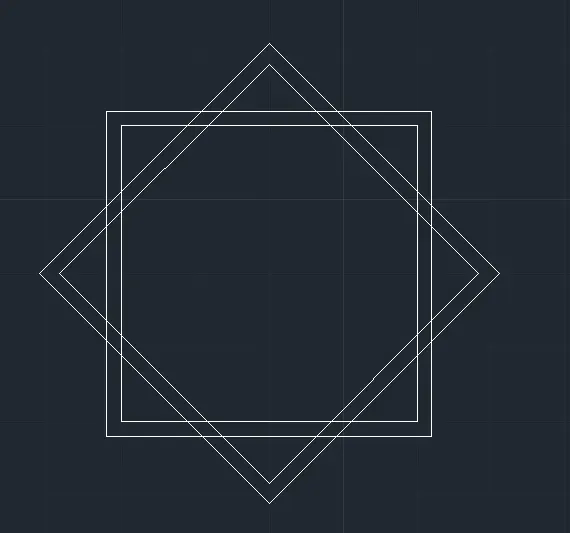
5. Type 'MO' in command line and select 'MOVE'
- Select objects: Select the rotated objects
- Specify base point or [Displacement] <Displacement>: Select the center of the rotated square
- Specify second point or <use first point as displacement>: Select the center of the first square
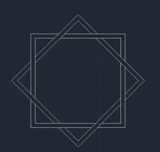
6. Trim unnecessary lines using 'TRIM' tool according to the design
Final Result:
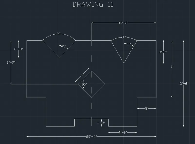
Drawing 11
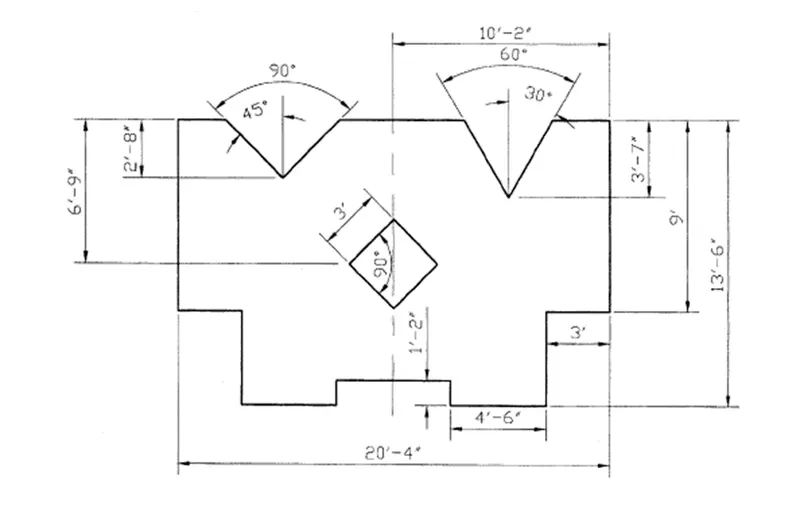
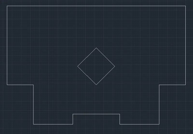
Before starting the drawing, change the length type to 'Engineering' and precision to '0'0"' in the 'Drawing Units'
1. Type 'L' in command line and select 'LINE'
- Specify first point: 10',5' (Assumed)
- Specify next point or [Undo]: 2'8"<180
- Specify next point or [Undo]: 1'2"<270
- Specify next point or [eXit/Undo]: 4'6"<180
- Specify next point or [Close/eXit/Undo]: 4'6"<90
- Specify next point or [Close/eXit/Undo]: 3'<180
- Specify next point or [Close/eXit/Undo]: 9'<90
- Specify next point or [Close/eXit/Undo]: 10'2"<0
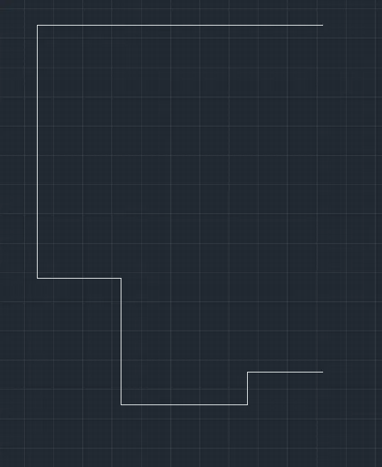
2. Type 'MI' in command line and select 'MIRROR'
- Select objects: Select all the objects
- Specify first point of mirror line: One end
- Specify second point of mirror line: Opposite end
- Erase source objects? [Yes/No] <No>: N
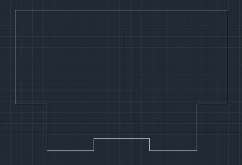
3. Type 'REC' in command line and select 'RECTANG'
- Specify first corner point or [Chamfer/Elevation/Fillet/Thickness/Width]: Using object snap tracking
- Specify other corner point or [Area/Dimensions/Rotation]: @3',3'
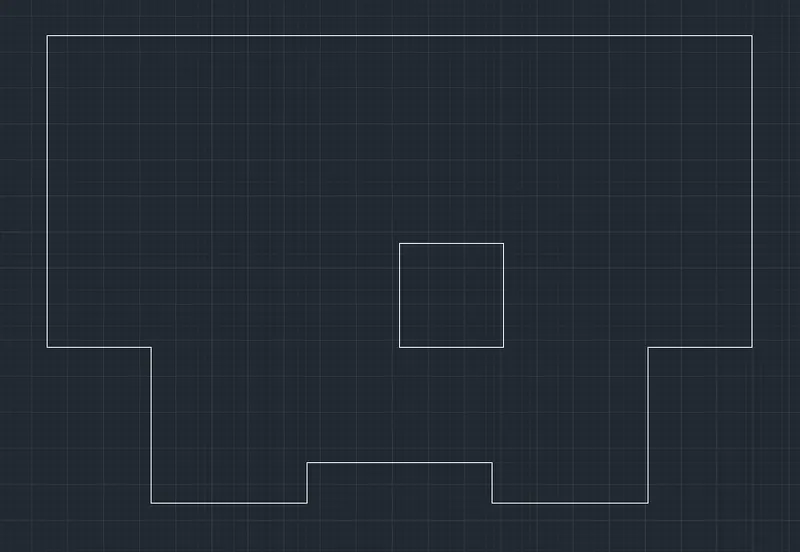
4. Type 'RO' in command line and select 'ROTATE'
- Select objects: Select the square (3',3')
- Specify base point: Select the base of the square (3',3')
- Specify rotation angle or [Copy/Reference]: 45
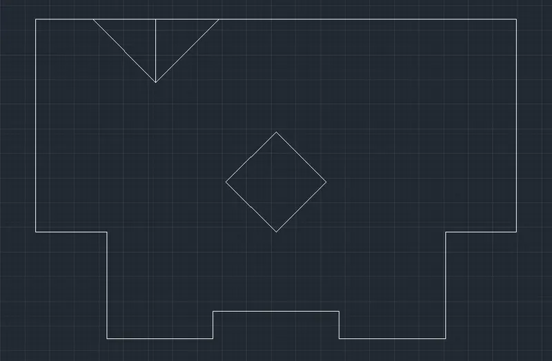
5. Type 'L' in command line and select 'LINE'
- Specify first point: Midpoint of the upper left 10'2"
- Specify next point or [Undo]: @2'8"<270
- Specify next point or [eXit/Undo]: Using polar tracking, draw a line <45 on both sides
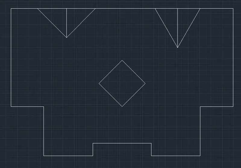
6. Type 'L' in command line and select 'LINE'
- Specify first point: Midpoint of the upper right 10'2"
- Specify next point or [Undo]: @3'7"<270
- Specify next point or [eXit/Undo]: Using polar tracking, draw a line <30 on both sides
7. Trim and erase unnecessary lines using 'TRIM' and 'ERASE'
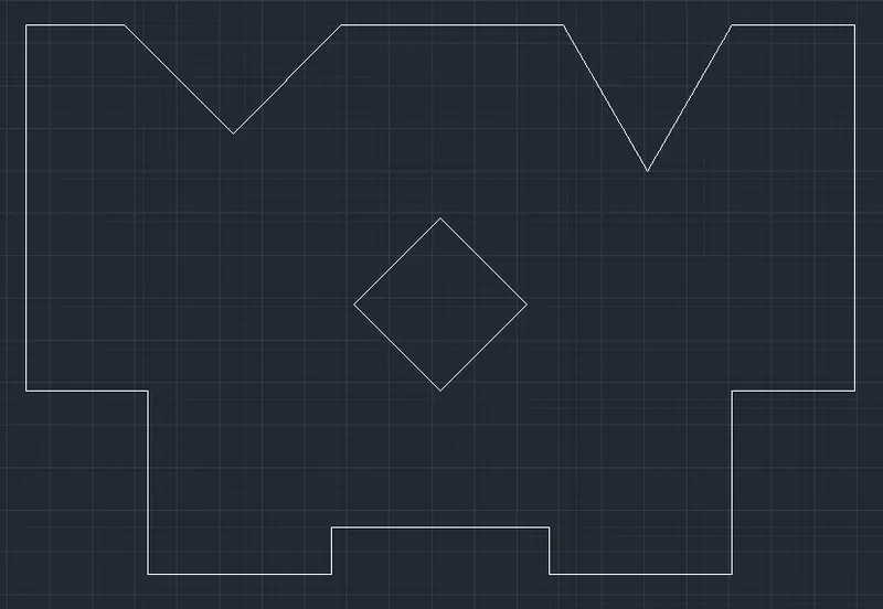
Final Result:
RESULT
Various geometries were drafted using different tools in the AutoCAD.