Sketch a G+1 residential plan according to Vaastu Shastra and Calculation of Loads as per IS code
AIM
- To sketch a G+1 floor residential plan, according to Vaastu Shastra and calculation of loads as per IS code.
- list down the names of the structural drawings required to be provided to the site for construction.
INTRODUCTION
To construct a residential building, the main important thing is the residential plan. The residential plan requires the details of directions depicting the magnitude such as North, South, East, and West, the layout of the building consisting of all the rooms, living room, kitchen, etc.., and all the dimensions for the layout. For every home, Vaastu Shastra plays an important role. Vaastu Shastra is an ancient Indian science of architecture and it acts as a guideline to design your home in a way that enhances positive energy.
EQUATION
- Dead load = Volume x Unit weight
PROCEDURE
Part 1:
1) In order to calculate the loads, a proper plan is required. The sketch of the ground floor plan and first-floor plan is given below.
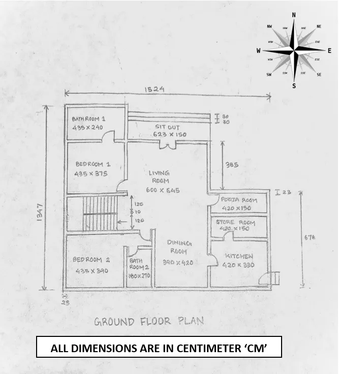
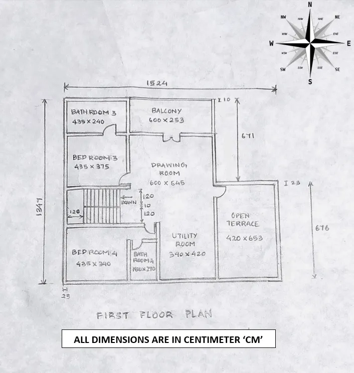
2) Dimensions for each layout of different floors are given in the below tables. Sizes of structural elements is also given below.
|
Dimensions of Ground Floor Plan |
|
|
Living Room Dining Room Bedroom 1 Bedroom 2 Bathroom 1 Bathroom 2 Sit Out Kitchen Store Room Pooja Room |
600cm x 645cm 390cm x 420cm 435cm x 375cm 435cm x 390cm 435cm x 240cm 180cm x 270cm 623cm x 150cm 420cm x 330cm 420cm x 150cm 420cm x 150cm |
|
Dimensions of First Floor Plan |
|
|
Drawing Room Utility Room Bedroom 3 Bedroom 3 Bathroom 4 Bathroom 4 Balcony Open Terrace |
600cm x 645cm 390cm x 420cm 435cm x 375cm 435cm x 390cm 435cm x 240cm 180cm x 270cm 600cm x 253cm 420cm x 653cm |
|
Sizes of The Structural Elements |
|
|
Dimensions of column |
300mm x 300mm |
|
Dimensions of beam |
300mm x 450mm |
|
Thickness of slab |
125mm |
|
Thickness of wall |
230mm |
|
Height of the wall of the ground floor |
4.5m |
|
Height of the wall of the first floor |
4m |
3) Calculation of loads
1. Dead Load Calculations
a. Dead load of column:
Dimension of column = 300mm x 300mm = 0.3m x 0.3m
Total no. of columns = 14
Slab thickness = 125mm = 0.125m
Height of column = Height of the wall of the ground floor + Height of the wall of the first floor + (Slab thickness x 2) = 4.5 + 4 + (0.125 x 2) = 8.75m
Total volume of column = 0.3 x 0.3 x 8.75 = 0.7875m3
Unit weight of concrete = 25 KN/m3 (As per IS 875 Part-1)
Dead load of one column = Volume of column x Unit weight of concrete = 0.7875 x 25 = 19.68 KN
b. Dead load of beam:
Dimension of beam = 300mm x 450mm = 0.3m x 0.45m
Total volume of beam per meter length = 0.3 x 0.45 x 1 = 0.135m3
Unit weight of concrete = 25 KN/m3 (As per IS 875 Part-1)
Dead load of beam per meter length = Volume of beam per meter length x Unit weight of concrete = 0.135 x 25 = 3.375 KN
c. Dead load of slab:
Thickness of slab = 125mm = 0.125m
Total volume of slab per sq. meter span area = 1m x 1m x 0.125m = 0.125m3
Unit weight of concrete = 25 KN/m3 (As per IS 875 Part-1)
Dead load of slab per sq. meter span area = Volume of slab per sq. m span area x Unit weight of concrete = 0.125 x 25 = 3.125 KN
d. Dead load of wall:
Thickness of wall = 230mm = 0.23m
Unit weight of brick wall = 20 KN/m3 (As per IS 875 Part-1)
Total height of the wall = Height of the ground floor wall + Height of the first floor wall = 4.5m + 4m = 8.5m
Dead load of wall per unit meter length = Volume of wall per unit meter length x Unit weight of brick wall = 8.5 x 0.23 x 1 x 20 = 39.1 KN
2. Live Load Calculations
As per IS 875 Part-2, for residential buildings, Live Loads are taken as;
- Living/Dining: 2KN/m3
- Kitchen: 2KN/m3
- Bedroom: 2KN/m3
- Bathroom: 2KN/m3
- Store Room: 2KN/m3
- Open Terrace: 3KN/m3
- Staircase: 3KN/m3
3. Wind Load Calculations
If the height of the building is more than 10m, then the building needs to be designed for wind load. Here, the height of the building is below 10m. Thus, wind load is not considered.
Part 2:
The names of the structural drawings required to be provided to the site for construction are:
- Centre line drawing
- Footing and column Layout with reinforcement details
- Column schedule with reinforcement details
- Plinth beam layout with reinforcement details
- Each floor beam layout with reinforcement details
- Lift pit and headroom with reinforcement details
- Each Floor plans
- Foundation plan
- Block plan
- Roof slab layout
- Column layout
- Column sections
- Septic tank detail
- Overhead water tank detail
- Furniture plan
- Road drainage plan
- Setting out a plan
- Section drawings of buildings
- Plumbing details
- Electrification details
RESULTS
1) A plan of a G+1 floor residential building according to Vaastu Shastra is done.
2) Calculation of loads is done as per the IS code for the residential building.
3) The structural drawings required for the construction site are mentioned.
CONCLUSION
The sketch of the G+1 floor of residential building is drawn with directions and all other needed details. Vaastu Shasta is followed through out for the design of each layout of the building. The load calculations are done as per the IS code 875:1987 (Part 1, Part 2, Part 3).