Project 1 _Creating an Architectural plan for the provided plot size and develop relevant basic structural drawings
Aim - To design the layout of a residential building of a dimension 60' x 20 ' with following
drawings -
A) Architectural drawings - i) Floor plan
ii) Elevations
iii) Sections .
B) Structural drawings - i) Column layout
ii) Beam layout
iii) Footing plan
Introductions -
i) The given residential building is designed with plot dimensions 60' x 20'.
ii) The orientation of building is facing East side .
iii) I have considered Ground floor residential building facing north side .
iv) The Building is designed with main door facing North - East direction .
Following are the dimensions assumed of a given building
1) Compound Wall - i) Compound wall is provided around the plot of the building .
ii) As per the General Requirements of the buildings the minimum distance between the
house and compound wall is 3.5m from front side and 1.5m from remaining sides .
iii) Assume the Height of the compound wall is 6' and thickness is 9" .(230 mm)
2) Columns and Beams - i) Assume the size of all columns are 9" x 12 " or 12" x9". (230 x 300)
ii) Similarly the size of all beams are 3' x 4 " (230 x 300 mm)
3) Doors - i) D = Dimensions of main doors = 4' x 7'
ii) D1= Dimensions of Bedroom Doors = 3' x 7'.
iii) D2 = Dimensions of toilet and Pooja room = 2'7" x 7'
4) Windows = i) W1 = Dimensions of main windows in L.R = 8' 10" x 4'11" (2700 x 1500mm)
ii) W2= Dimensions of kitchen Windows = 8' x 4'11" (2500 x 1500mm)
iii) W3 = Dimensions of Master bed room = 3'3" x 4'11" (1000 x 1500mm)
iv) V = Dimensions of Ventilators = 2'8" x 1'8" ( 800 x 500mm)
5) Walls - i) Assume External wall thickness = 9" ( 230mm)
ii) Assume Internal wall thickness = 4.9" (125mm )
Procedure -
i) Open a New drawing (Cntrl + N) select Imperical units ( Feet and Inches )
ii) Select units to Engineering and select precision as Inches (0'0.0")
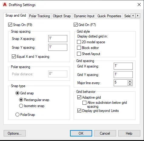
iii) Command DS / Drafting settings - Change the Snap spacing and Grid spacing 1' and Change major lines
every grid to 5 .
iv) Dimensions -i) Give Command D and press enter
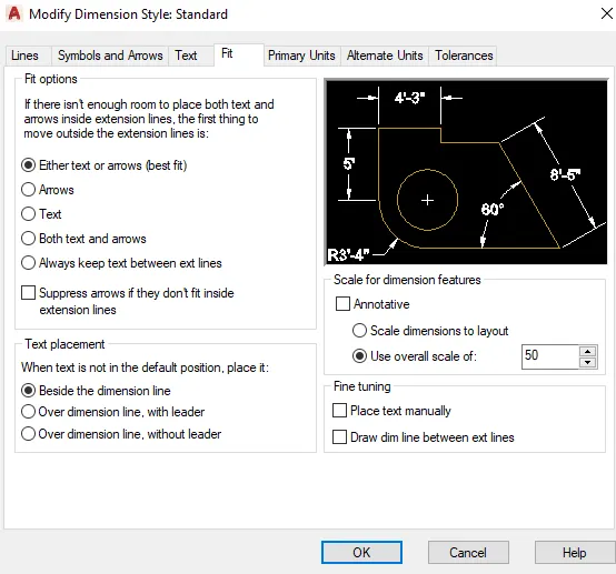
ii) Select Standard and then go for modify .
iii) Select Fit and USe overall Scale to 50 .
iv) Make the primary units to Engineering and precision 0'0.0"
v) If you want you can on Alternate units also.
Step by Step Procedure - All the Dimensions are in Feet and Inches .
Step 1) Draw a plot directions
i) Take the directions as per our building plan and Draw the directions .
ii) Give the command Ln / Lines .
iii) Draw the two perpendicular lines and give the text as N , S , E , W
iv) For text give command DT.
v) Justify - Center
vi) Text point - Above the lines
vii) Text angle - 0 degree
viii) Text height - 2'
ix) Press Enter and write the texts

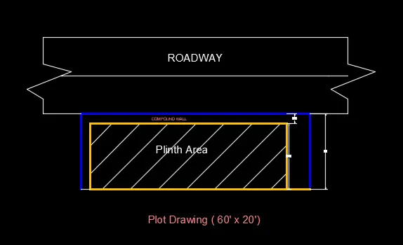
Step 2) Create the plot line ( 60' x 20')
i) Give the command Ln
ii) Draw the line of 10' ( Shows the Road line )
iii) Take the offset at 6' and draw the parallel lines .
iv) Now take the base point of 1st line and Command Rectangle .
v) Enter length = 60' (As our building facing East sides )
vi) Enter Width = 20'
vii) Take the Offset = 2'8" from Road line to draw the compound wall .
viii) Take offset = 6' from East side of plot to draw compound wall and 2'3" from West side.
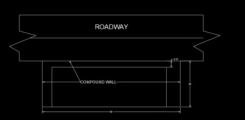
ix) Command Qleader - Show the Direction of Compound wall and Add leaders and give the directions .
x) Command Hatch - Select the object
xi) Patern - ANSl132
xii) Hatched the pinth area as shown in fig .
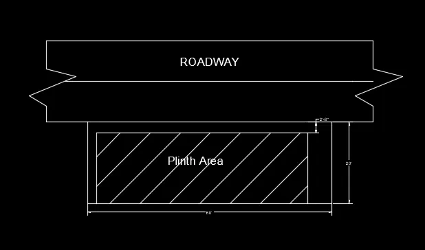
xiii) Remaining Dimensions = ( 51'9" x 17'4'')
xiv) The proposed building should lie inside the the compound wall .
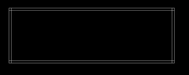
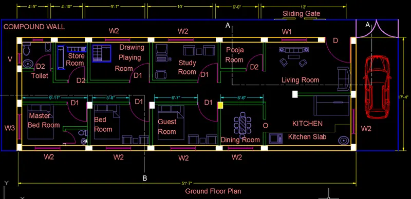
Step 3) Create the External walls
i) Command Offset
ii) Give offset distance 9" from all sides to draw the external walls .
Step 4) Living Room -
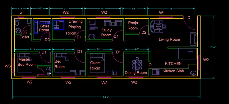
i) Assume the size of Living room is 18' x 8' ( 4m x 2.5 m)
ii) Command offset
iii) Give offset distance 18' from east to -ve x direction .
iv) Repeat command and enter distance 8' to -y direction .
v) Command Offset at 4.9" to both the lines to draw internal wall .
vi) Give the opening of 6' to draw Door D .
Step 5) kitchen -
i) Assume the size of Kitchen room is 18' x 8' ( 4m x 2.5 m)
ii) Command offset
iii) Give offset distance 18' from east to -ve x direction .
iv) Repeat command and enter distance 8' to -y direction .
v) Command Offset at 4.9" to both the lines to draw internal wall .
vi) Give the opening of 4' to draw Door D1 .
Step 6) Dining Room -
i) Assume the size of Kitchen room is 6' 6" x 8' ( 2m x 2.5 m)
ii) Command offset
iii) Give offset distance 6'6" from east to -ve x direction from kitchen .
v) Command Offset at 4.9" to draw internal wall .
vi) Give the opening of 4' to draw Door D1
Step 7) Guest Room -
i) Assume the size of Guest room is 10' x 8' ( 2m x 2.5 m)
ii) Command offset
iii) Give offset distance 10' from east to -ve x direction from Dining Room
v) Command Offset at 4.9" to draw internal wall .
vi) Give the opening of 4' to draw Door D1
Step 8) Bed Room 1
i) Assume the size ofBed room 1 is 9' 1" x 8' ( 2.7m x 2.5 m)
ii) Command offset
iii) Give offset distance 9'1" from east to -ve x direction from Guest Room
v) Command Offset at 4.9" to draw internal wall .
vi) Give the opening of 4' to draw Door D1
Step 9) Master Bed Room -
i) Assume the size of Kitchen room is 10' x 8' ( 2m x 2.5 m)
ii) Command offset
iii) Give offset distance 10' from east to -ve x direction from Bed Room 1
v) Command Offset at 4.9" to draw internal wall .
vi) Give the opening of 4' to draw Door D1
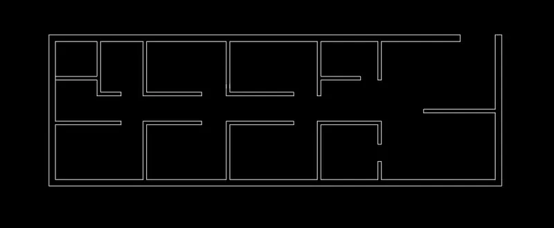
Step 10) Passage
i) Command offset
ii) Give offset distance 2'5" from Master bed Room in + ve direction ( i.e Horizntally ) .
iii) Command Extend
iv) Join the line till the Living room .
v) Command Offset 4.9" to the internal walls .
Step 11) Toilet
i) Assume the size of Toilet is 4'9" x 4' ( 1.5 m x 1.2 m)
ii) Command offset
iii) Give offset distance 4'9" from west to +ve x direction from North - West direction .
v) Command Offset at 4.9" to draw internal wall .
vi) Give the opening of 4' to draw Door D2
Step 12 ) Store Room -
i) Assume the size of Store Room is 4'10" x 5'10" ( 1.5 m x 1.7 m)
ii) Command offset
iii) Give offset distance 4'9" from west to +ve x direction from Toilet
v) Command Offset at 4.9" to draw internal wall .
vi) Give the opening of 4' to draw Door D1
Step 13) Drawing and Playing Room .
i) Assume the size of Drawing and Playing Room is 9'1" x 5'10" (2.7 m x 1.7 m)
ii) Command offset
iii) Give offset distance 9'1" from west to +ve x direction from Store room
v) Command Offset at 4.9" to draw internal wall .
vi) Give the opening of 4' to draw Door D1.
Step 14) Study Room
i) Assume the size of Study Room is 10' x 5'10" (3 m x 1.7 m)
ii) Command offset
iii) Give offset distance 10' from west to +ve x direction from Drawing and Playing Room
v) Command Offset at 4.9" to draw internal wall .
vi) Give the opening of 4' to draw Door D1.
Step 15) Pooja Room
i) Assume the size of Pooja Room is 6'6" x 4" (2 m x 1.2 m)
ii) Command offset
iii) Give offset distance 6'6" from west to +ve x direction from Study Room
v) Command Offset at 4.9" to draw internal wall .
vi) Give the opening of 4' to draw Door D1.
Note - Trim the unwanted lines by giving command Trim .
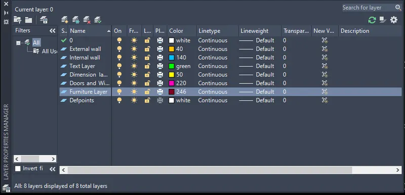
Step 16) Create Layers -
i) Command LA
ii) Create New Layers
iii) External wall layer - colour- Continuous type
iv) Internal wall layer - colour- Continuous type
v) Text layer - colour- Continuous type
vi) Dimension layer
vii) Furniture layer
viii) Doors and Windows layer
Note - More Layers needs to be add . Once we moved further more layers are required .
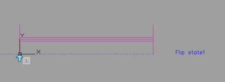
Step 17 ) Create a block of Dooors and Windows
First Create Door in Autocad .
i) Create a block of Doors and window so it will be helpful to directly assign to the respective rooms .
ii) For D (4' x 7')
iii) Command Ln ( Select layer as Doors )
iv) Draw the line of 4'
v) For Door frame is required
vi) Command Rectangle
vii) Enter length = 1.5"
viii) Enter Width = 3"
ix) Mirror the frame by giving command MI and selecting midpoint of the line
ix) Draw the hinges
x) Command LN
xi) Draw the line in +y direction and take offset of 0.1" from frame
xii) Take offset 0.75" to draw panel thickness .
xiii) Command Circle
xiv) And Draw the circle by taking
xv) Draw the Circle from the bottom of the hinges and join it to midpoint of the next frame .

xvi) Now give command Block / B
xvii) pick point - select base point
xviii) Select object - Convert into block - press Okay .
xix) Command Bedit select Doors 4' press okay .
xx) Parameters - Flip
xxi) Parameters action - Flip and test the block .
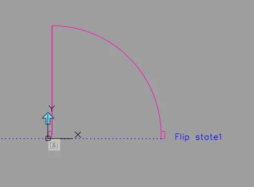
xxii) Simiarly follow the same procedure for other doors and Windows .
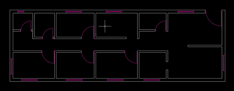
xxiii) Assign the Doors and Windows in respective rooms .
xxiv) Coomand Inset
xxv) And Copy the blocks of Doors and Windows to the rooms .
Step 18) Insert the Blocks by Command ADC
i) Give Command ADC
ii) Insert the blocks like ( Toilet , Dining table , Bedroom etc etc )
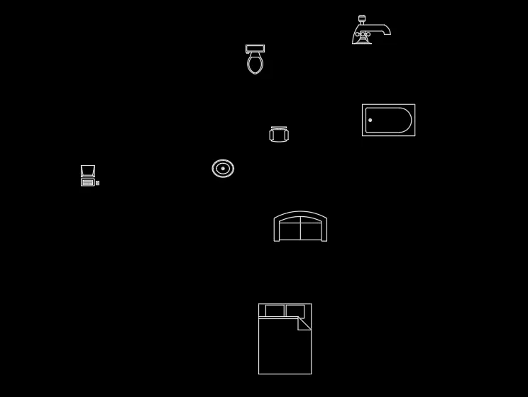
iii) Assign the furnitures in respective rooms .
iv) Command I / Insert
v) Copy the blocks into the rooms .
vi) Select the respective layers which we have created earlier .
vii) Assign the layers to wall furnitures etc .
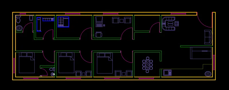
Step 19) Dimensions and Annotations .
i) Dimensions procedure is already mentioned above
ii) Follow that procedure and give the dimensions .
For Annotations -
i) Command DT
ii) Justify - Left
iii) Style - Arial
iv) Specify text point
v) Text ht - 2'
vi) Text angle - 0
vii) Press Enter .
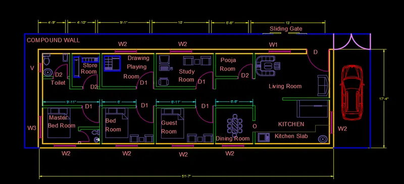
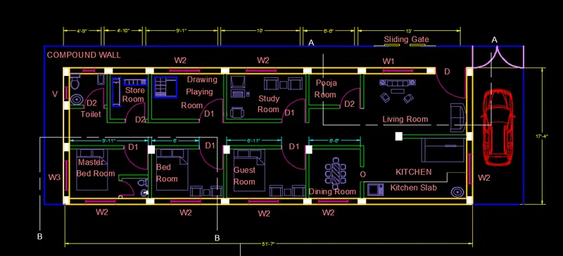
Results of Floor Plan -
i) Compound wall is shown around the floor plan which is mentioned earlier steps .
ii) Insert the Car block inside the compound wall
iii) Sliding gate is inserted by adc command .
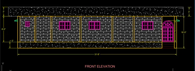
B) Elevations - ( Front Elevations )
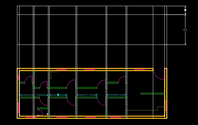
Step 1) Draw the projections
i) Turn off Dimensions layer , Compound wall layer , text layers etc
ii) Coomand XL
iii) Draw the Vertical Projections of North side .
iv) Mark all the external as well as internal walls .
v) Assume the height 10'5" from Ground floor to top . Command Offset and enter distance
vi) Height of roof 3' . Command offset and enter distance from last lines .
vi) Command Trim - trim unwanted lines
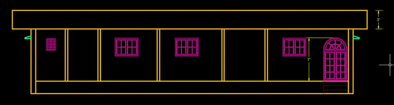
Step 2) Projections of Doors and Windows -
i) Take the projections of doors and windows
ii) Follow the Step 1
iii) Draw the doors and windows .
iv) Command adc .
v) Insert the blocks of Doors and windows from the available options.
vi) Change the layer from Layers option - Doors ans Windows .
Step 3) Hatching -
i) Show the Brick wall by hatching.
ii) Show the PCC at Plinth level and at top .
iii) Command Hatch
iv) Select Pattern AR-B816 and Concrete work .
v) Select the object and apply the command
vi) Increase the scale if its not visible .
vii) Change the layer colour of hatching -Gray
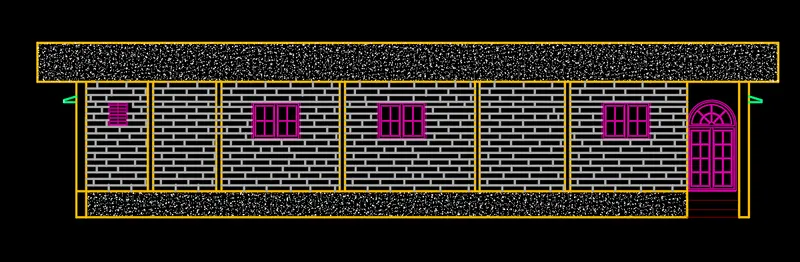
Step 4) Dimensions -
i) Give the dimensions whatever we have assumed .
ii) Follow the same procedure which we have mentioned earlier to give dimensions .
For Steps-
iii) Riser - 6"
iv) Tread = 9"
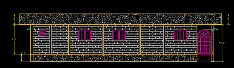
Results - Elevation of plan is drawn .
C) Section -
Step 1) Draw section line
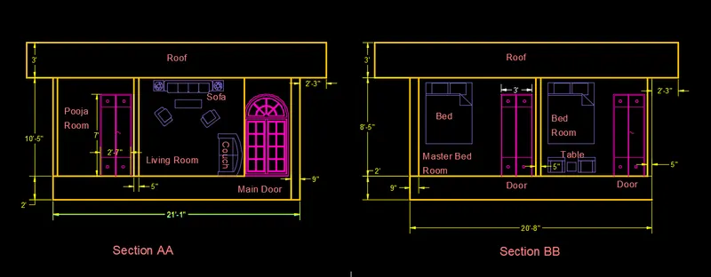
i) Cut a section as A-A and B-B as shown in fig .
ii) Change the layer of line to long dash - short dash .
iii) Command LA
iv) Add layer - Section AA and BB
v) Change line type - long dash - short dash .
vi) Press enter.
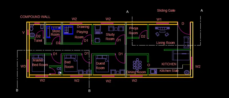
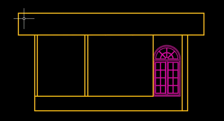
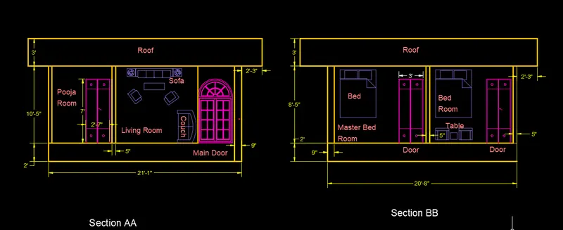
Step 2) Section AA
i) Command XL - v
ii) Take the projection of Living Room and Pooja Room ( Because section is cut through living room and
pooja room )
iii) Assume the height as 10'5" .
iv) take offset at 10'5"
v) Again take offset of 3' for top roof .
vi) Trim the unwanted lines .
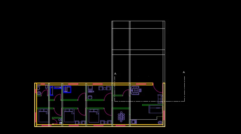
Step 3) Living Room -
i) Take the projection of Doors and windows .
ii) Copy the door of Living room from Elevations .
iii) Command Copy
iv) Select object
v) Specify base point
vi) And press enter and specify next point where we have to copy .
Step 4) Furniture-
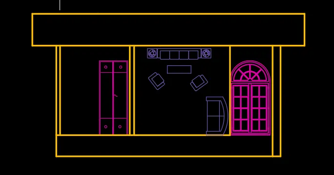
i) Furniture are also visible when we cut the section AA
ii) Sofa Blocks are added to the section by importing autocad blocks from internet .
Step 5) Pooja Room -
i) In Pooja Room only Door is visible .
ii) Draw the door D2 by using Ln command ( 2' 7" x 7')
Step 6) Section BB -
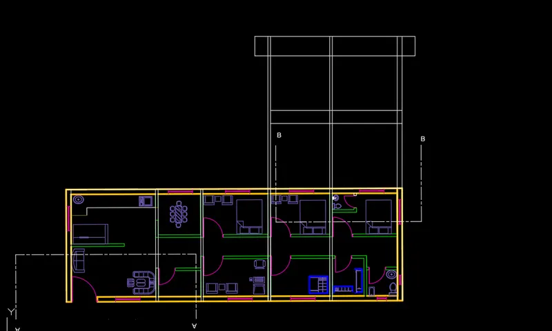
i) For Section BB , rotate the plan in 270 degree.
ii) Command Rotate
iii) Enter angle 270.
iv) Command XL - v
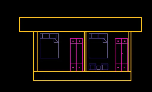
v) Take the projection of Bed Room and Master Bed Room .
vi) Assume the height as 10'5" .
vii) Take offset at 10'5"
viii) Again take offset of 3' for top roof .
ix) Trim the unwanted lines .
Step 7) Bed Room -
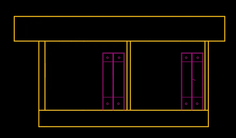
i) To draw the Door D1 ( 3' x 7')
ii) Comand Ln .
iii) Draw a line of (@3' , 0)
iv) Specify next point (@0 , 7')
v) close .
vii) Take the offset of 1" from all side .
viii) Take the midpoint from X and Y directions . and draw the line .
ix) Take offset of 1' from top and bottom to show the design of frame .
x) Draw the circles as shown in fig ( R = 1")
xi) Copy to all 4 sides as shown in fig .
Step 8) Master bed room .
i) Copy the same door as the sizes are same .
ii) Command Copy
iii) Select object
iv) Specify base point
v) And press enter and specify next point where we have to copy .
Step 9) Furnitures
i) Command I
ii) Insert the Bed room block in Bed room and Master bed room .
iii) Again give Command I
iv) Insert the table block in Bed Room as it is also visible when we cut the sections .
Step 10) Dimensions and Annotations - Section AA and BB
Dimensions -
i) Give Command D and press enter
ii) Select Standard and then go for modify .
iii) Select Fit and USe overall Scale to 50 .
iv) Make the primary units to Engineering and precision 0'0.0"
v) If you want you can on Alternate units also.
For Annotations -
i) Command DT
ii) Justify - Left
iii) Style - Arial
iv) Specify text point
v) Text ht - 7"
vi) Text angle - 0
vii) Press Enter .
2) Structural Drawings -
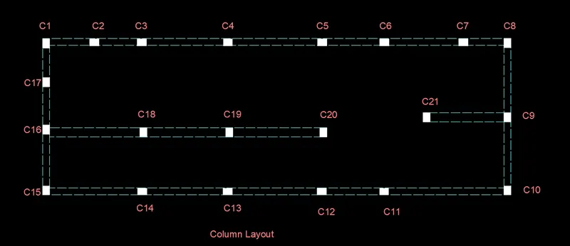
A) Column Layout -
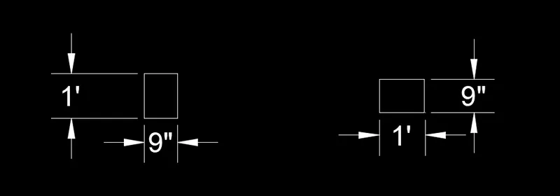
Step 1) Show the location of columns in plan
i) Mark the position of the positions of column .
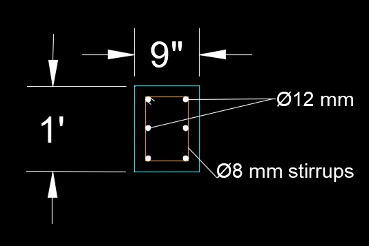
ii) Columns Sizes are 9' x 12" or 12" x 9"
iii) Show it by Hatch .
iv) Command Hatch .
v) Select pattern Solid fill
vi) Change the color -
vii) Assume columns wherever it is necessary .
viii) Distance between two columns should not be more than 4 m.
Step 2) Draw column Layout .
i) Turn off all the layers except columns.
ii) Command Copy
iii) Copy the columns to the other side of plan
iv) Command LA
v) Name it as Column layer
vi) Select line type - dash line
vii) line weight - 30mm
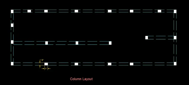
viii) Colour - red .
ix) Join the column by this layer .
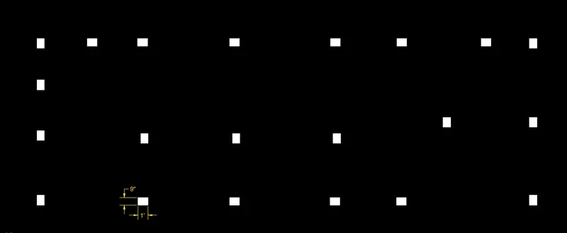
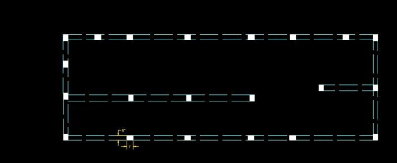
x) A reinforcement details is also shown for column .
Result - Column Layout is drawn for given plan .
2) Footing Layout .
Step 1)
i) Create a Column layout again .
ii) Join the lines again.
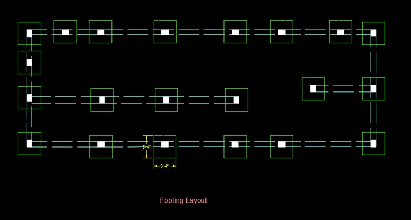
iii) Provide footing size as 1m x 1m ( 3'4" x 3'4" )
iv) Command Rec -
v) Enter length - 3'4"
vi) Enter width = 3'4"
vii) Press Enter .
viii) Command LA - Footing layer
ix) Draw the footing with this layer.
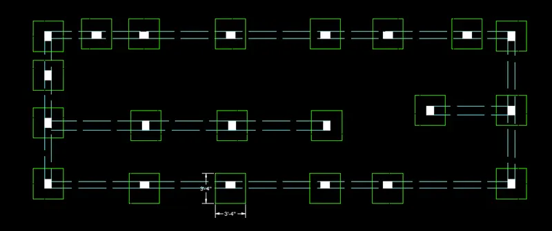
Result - Footing Layout is drawn .
3) Beam Layout .
Step 1) Marking of Columns for beams .
i) Make the all layers off except column layout layer .
ii) Copy that diagram to the side .

Step 2) Draw the beam
i) Command LA - Beam layer
ii) Select line type - dashed
iii) line weight - 0
iv) Select colour
v) Join the beams by using LN command
vi) It would be similar to ground floor plan
vii) One beam will be add in kitchen room .
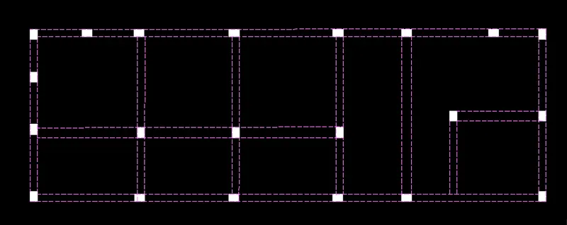
Step 3) Beam Reinforcement -
i) Beam reinforcement details is shown -
ii) Command Rec
iii) Enter Length = 3'4"
iv) Enter width = 3'4"
v) Press Enter
vi) Command Offset - Provide cover 25mm
vii) Press enter
viii) Show the reinforcement as shown in fig - ( 4 -12 dia )
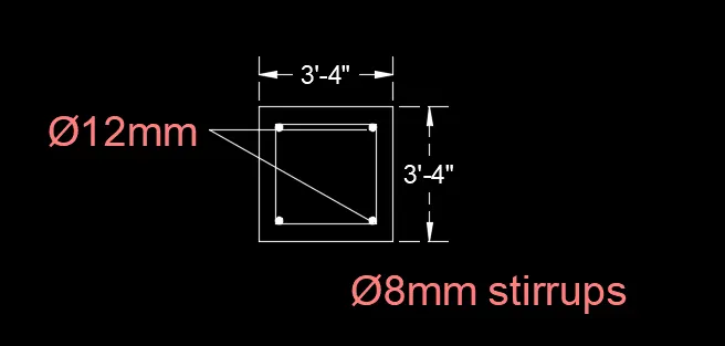
Step 3) Dimensions -
i) Give Command D and press enter
ii) Select Standard and then go for modify .
iii) Select Fit and USe overall Scale to 50 .
iv) Make the primary units to Engineering and precision 0'0.
v) If you want you can on Alternate units also.

Results - Beam layout is drawn
Overall Result -
i) Residential plan which consists Ground Floor is drawn as per Vastu Shashta .
ii) Residential design of ground floor consists Plot Drawing , Plan , Elevations , Sectons , Beam
Column footing layout .
iii) All the procedures are shown by step by step .
iv) The given design is according to the Vastu Shashtra .
Following principles are used -
a) Entrance of the house is at the North or North East direction .
b) Center of house is free from obstructions .
c) Kitchen is provided in South - East direction
d) Bedroom is provided in South and South west direction
e) Toilet is provided at North East direction
f) Store room and Drawing room is provided at North west direction .
Final Results - It comprises all the individuals results .
1) Plot Diagram and Compound wall -
2) Ground Floor Plan -
3) Elevations -
4) Section - AA and BB
5) Column layout -
6) Footing Layout -
7) Beam layout -