Project 1 _Creating an Architectural plan for the provided plot size and develop relevant basic structural drawings
AIM
To draw Architectural Drawings of Floor Plan, Elevations, and Sections and also the Structural Drawings of Column, Beam and Footing Plan
INTRODUCTION
- Architectural and structural drawings are generally considered to be the drawings of steel, wood, concrete and other materials used to construct buildings, ships, planes, bridges, towers, tanks, and so on.
- A structural drawing, a type of engineering drawing, is a plan or set of plans and details for how a building or other structure will be Built
- Structural drawings are generally prepared by registered professional engineers, and based on information provided by architectural drawings.
- The structural drawings are primarily concerned with the load-carrying members of a structure.
- They outline the size and types of materials to be used, as well as the general demands for connections
- Architectural drawings are used by architects and others for a number of purposes to develop a design idea into a coherent proposal to communicate ideas and concepts,
- To convince clients of the merits of a design, to assist a building contractor to construct it based on design intent, as a record of the design and planned development, or to make a record of a building that already exists
COMMANDS USED
- Limits command
- Line command
- Offset command
- Hatch command
- Dimlinear command
- Dimstyle command
- Units command
- Extend command
- Fillet command
- Trim command
- Join command
- Circle command
- Line weight command
- Line type command
- Object snap command
PROCEDURE
ARCHITECTURAL DRAWINGS OF FLOOR PLAN ELEVATIONS AND SECTIONS
STEP-1
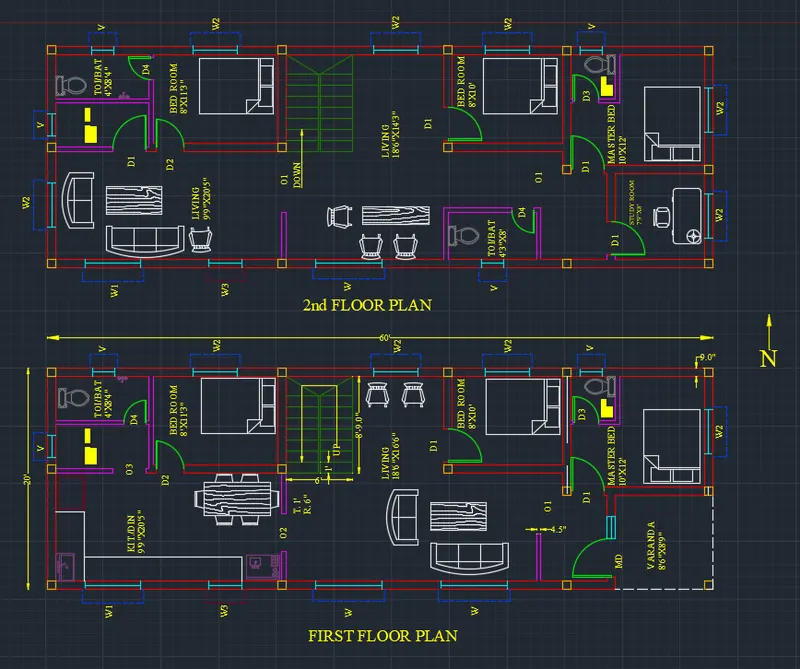
FIRST Floor Plan
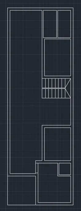
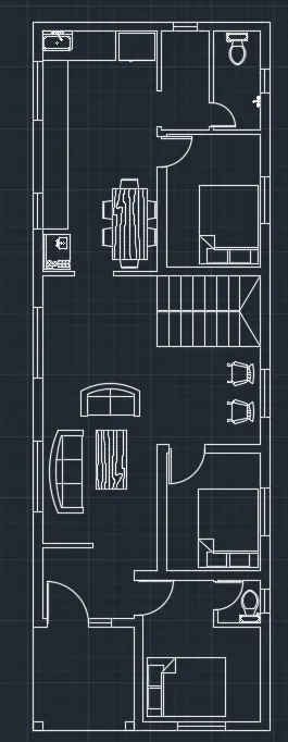
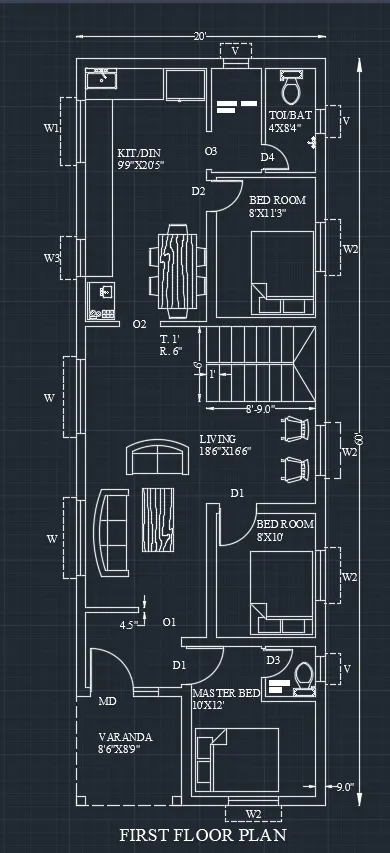
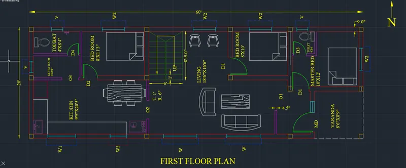
- First draw the plot area and building area using the line command and dimlinear command as shown in the below figure.
- Next draw the line horizontally forward with the length of 20’ And next again draw the line upwards from the previous line with the length of 60’
- From the top from previous line again we draw the line backwards with the length of 18’4" Next from previous line we draw the line downwards with the length of 3’9”
- Now from the left side comer of the 1st line we draw another line from that edge with the length of 10’
- Next join the to edges with the small horizontal line to join them, as shown in the below figure.
- Now we draw the master bedroom with the size of 10’6”x9’5” Next the attached toilet with the size of 5’x8’6”
- Next the Guest bed room with the size of 10’6”x9’5” Next draw the attached toilet with the size of 5’6” degrees
- Next draw the store room with the size of 5’5” * 7’9”
- Next draw the Living/drawing room with the size of 9’5” * 17’9” using the line command and trim command.
- Next draw the kitchen room and dining room with size of 9’5” * 15’3”
- draw the waiting room with the size of 9’5” * 10’6” Next draw the staircase with the tread of 12 inches and riser of 6 inches, and also draw the entrance gate facing east
- draw the all doors with the size of 3’6”’x7’ except toilet doors.
- draw the toilet doors with the size of 2’x7’ Next draw the all windows with the size of Then after we use the dimlinear command to put the dimensions to the rooms.
- Next draw the furniture things where they are required. Now we select the single text command.
- draw the direction symbol using the cirde command, line command and text command as shown in the below figure Finally, we indicate the total drawing using the single text command as Ground floor plan as shown in the figure.
STEP-2
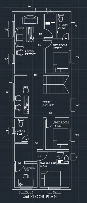
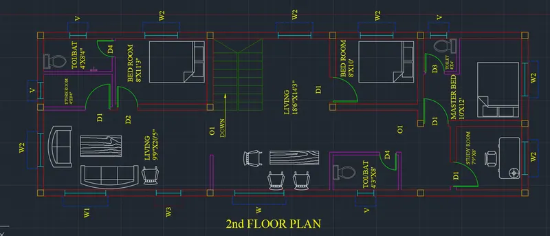
Second floor plan
- draw the line horizontally forward with the length of 20’
- And next again draw the line upwards from the previous line with the length of 60’ From the top from previous line again we draw the line backwards with the length of 18’4” Next from previous line we draw the line downwards with the length of 39’9’
- Now from the left side corner of the 1st line we draw the another line from the edge with the length of 10’11”
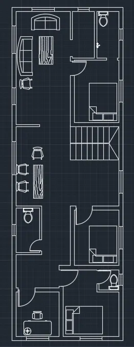
- Next join the two edges with the small horizontal line to join them, as shown in the below figure. Now we draw the master bedroom with the size of 10’x12’
- draw the attached toilet with the size of 4’ x 4’
- draw the bed room with the size of 8’x10’
- draw the toilet with the size of 4’x8’
- draw the extra room with the size of 4’x8’
- Next draw the Living room with the size of 9-5' x 11-9"
- Next draw the kitchen room and dining room with size of 9’5” x 15’3”
- draw the waiting room with the size of 9-5" x 10-6" line command and trim command.
- Next draw the staircase with the tread of 12 inches and riser of 6 inches, and also draw the entrance gate facing east
- Next draw the all doors with the size of 3’x7’ except toilet doors
- Next draw the toilet doors with the size of 2’x7’
- draw the all windows with the size of 5’x4’
- Then use the dimlinear command to put the dimensions to the rooms
- draw the furniture things where they are required. Now we select the Single text command to indicate the rooms.
- draw the direction symbol using the circle command, line command text command as shown in the below figure and
- Finally, indicate the total drawing using the single text command as Ground floor plan as shown in the figure.
STEP-3
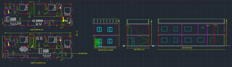
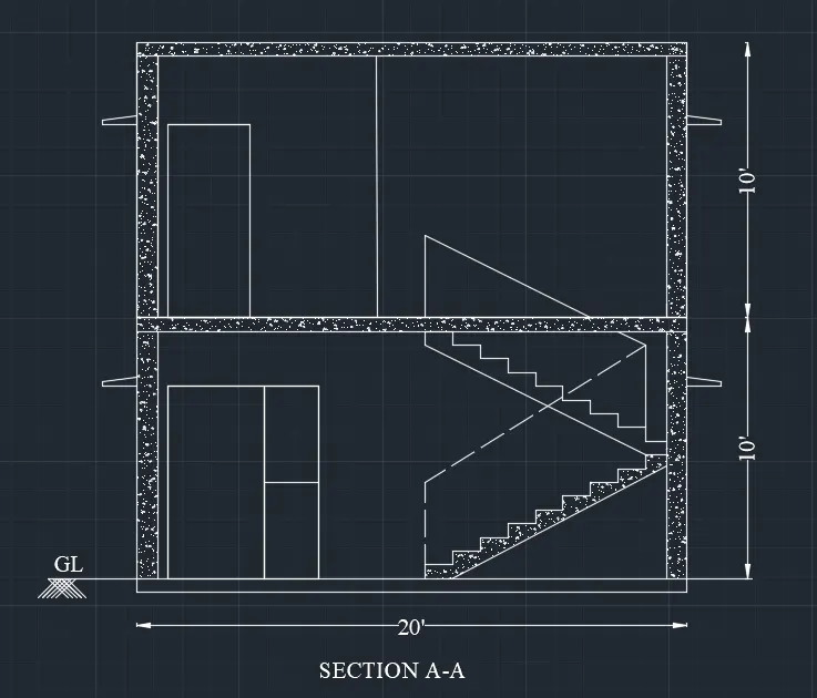
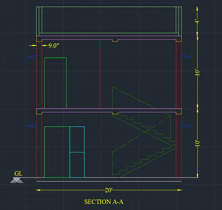
Section A-A
- First of all draw the line with the length of 20’ horizontally
- Next draw a line from previous line with the length of 24’ vertically upwards.
- From the precious line, draw the line backwards with the length of 20’ horizontally.
- Next join the first line and the last line with the length of 24’
- Next draw the staircase using the line command with the12 inches tread and 6 inches riser. And also draw the railing to the stairs to look good in the front view.
- Next draw the doors and windows in the ground floor and first floor as shown in the below figure and draw the water tank on the top at left side of the building
- Finally put the dimensions where ever they required using the dimlinear command.
- And write the elevation name downside of the drawing using the single text command.
STEP-4
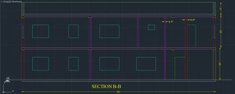
Section B-B
- First draw the line with the length of 60’ using the line command.
- And then offset that line with the length of 150mm offset
- Next draw the vertical line from the left side corner of the first line with the length of 23’
- Next draw the floors using the line command and offset command
- Next draw the doors and windows with the help of line command and trim command.
- The thickness of slabs are 6’ for both floor slabs.
- Finally put the dimensions where ever they required using the dimlinear command.
- And write the elevation name downside of the drawing using the single text command
STEP-5
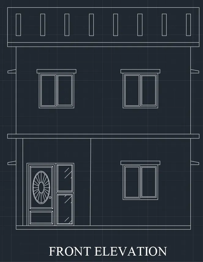
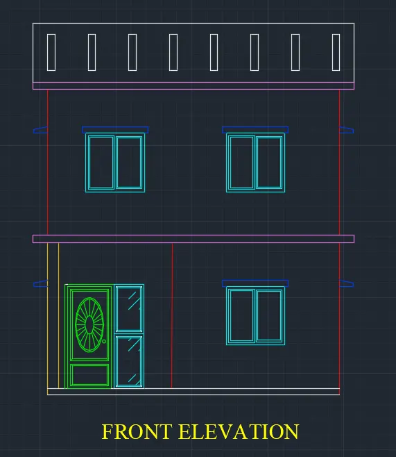
Front elevation
- First of all draw the line with the length of 20’ horizontally
- Next draw a line from previous line with the length of 24’ vertically upwards.
- From the precious line, draw the line backwards with the length of 20’ horizontally.
- Next join the first line and the last line with the length of 24’
- Next draw the staircase using the line command with the12 inches tread and 6 inches riser. And also draw the railing to the stairs to look good in the front view.
- Next draw the doors and windows in the ground floor and first floor as shown in the below figure and draw the water tank on the top at left side of the building
- Finally put the dimensions where ever they required using the dimlinear command.
- And write the elevation name downside of the drawing using the single text command.
STEP-6
Schedule Of Openings
- Main Door, MD 3'6" X 7'
- Door-1 D1 3' X 7'
- Door-2 D2 2'6" X 7'
- Door-3 D3 2'4" X 7'
- Door-4 D4 2' X 7'
- Opening-1 O1 5'6" X 9'
- Opening-2 O2 3'4" X 9'
- Opening-3 O3 3' X 9'
- Window W 6' X 4'
- Window-1 W1 5' X 4'
- Window-2 W2 4' X 4'
- Window-3 W3 3' X 4'
- Ventilator V 2' X 1'6"
STRUCTURAL DRAWING OF COLUMN, BEAM AND FOOTING PLANS
STEP-1
Column plan
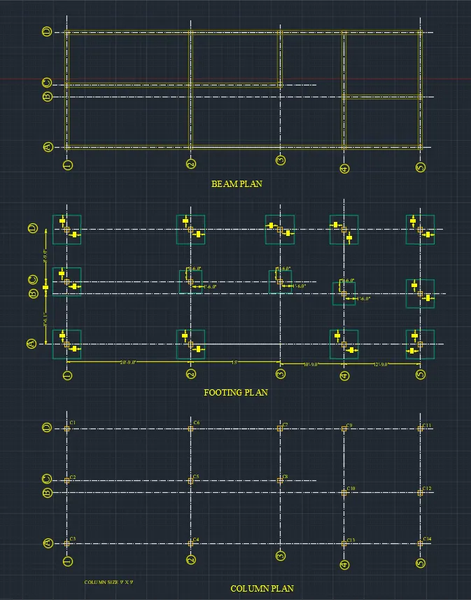
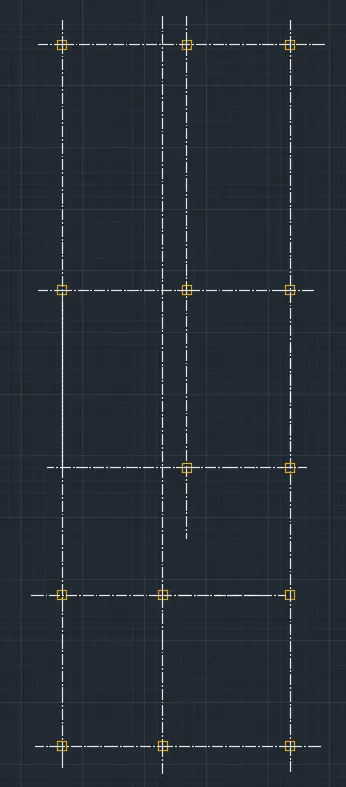
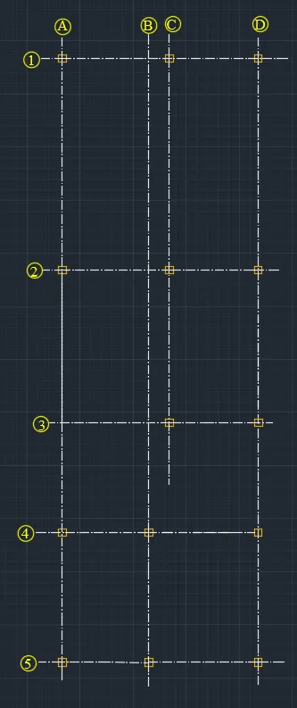
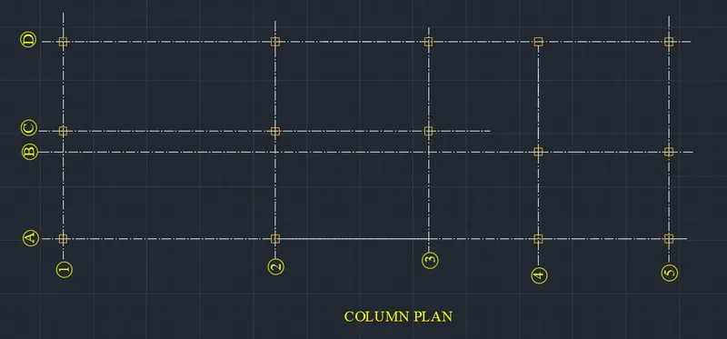
- First draw the grid lines with the centre line distance of plan as shown in the below figure.
- Next Indicate the vertical lines with the alphabets
- And next indicate the horizontal lines with the numbers, as shown in the figure below
- Next draw the columns where they are required in the figure C1, C2, C3, C4, C5, C6, C7, C8, C9, C10, C11, C12, C13, and C14
- Next use the single text command to indicate the columns with C and numbers with 1, 2, 3…etc
- Next use the single text command and write the text as 'Column Plan' downwards to the figure.
STEP-2
Beam Plan
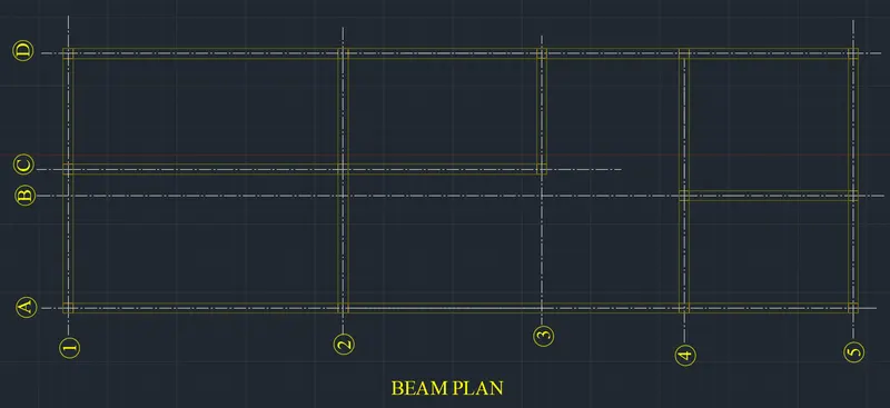
- First draw the grid lines with centre line distance of plan as shown in the below figure
- Next indicate the vertical lines with the alphabets.
- And next indicate the horizontal lines with the numbers, as shown in the figure below
- Next draw the columns where ever they are required in the figure
- Next draw the beams using the line command with reference to the columns.
- Next put the dimensions where ever they required using the dimlinear command, and the beam size is taken as 9’x9’
- Next use the single text command and write the text as 'Beam plan' downwards to the figure.
STEP-3
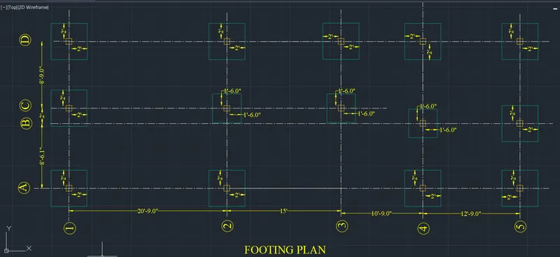
Footing Layout
- First draw the grid lines with the help of centre line of plan as shown in the below figure
- Next Indicate the vertical lines with the alphabets, and next indicate the horizontal lines with the numbers, as shown in the figure below.
- Next draw the column and footing with the required dimensions.
- We take the column size as 9’ x 9’
- Next do the offset of 2’ horizontally and vertically from the columns to form the footings.
- Then draw the footing layout with required dimensions
- Finally put the dimensions in every part of the drawing using the dimlinear command
- Next use the single text command and write the text as Footing Layout downwards to the figure
RESULT
The Architectural Drawing (Floor Plan, Elevations, and sections) and the Structural Drawing (Column, Bean and Footing Plan) are created successfully using AutoCAD 2022 software.