Project 1 - Controlling a DC motor using PWM and monitoring its Running status
LIVE BATCH STUDENT
Implement a system for controlling a DC motor using L293 driver and print running status of motor in the LCD screen.
Simulate the hardware in simul IDE
PROGRAM:
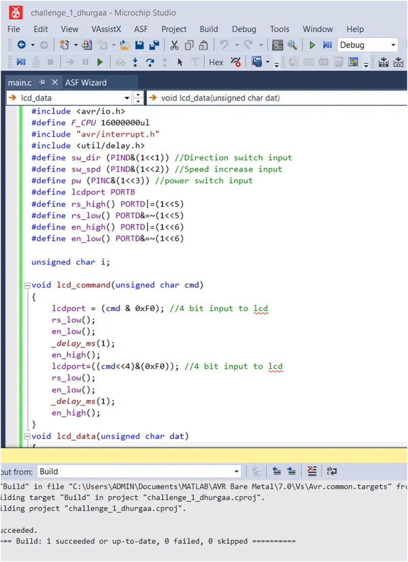
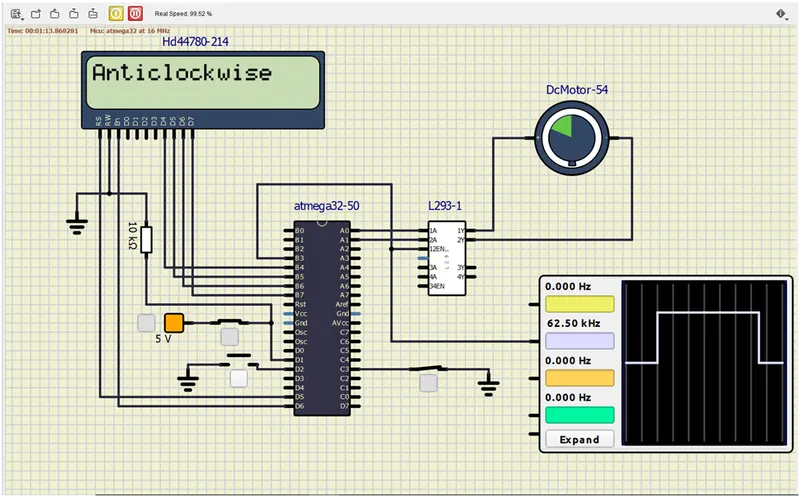
The program has three inputs one for power switch, direction control switch and Speed switch. The power switch and speed switch are programmed with internal pull-up resistors. PORTB (4 pins) are connected to LCD to display the status of the DC motor.
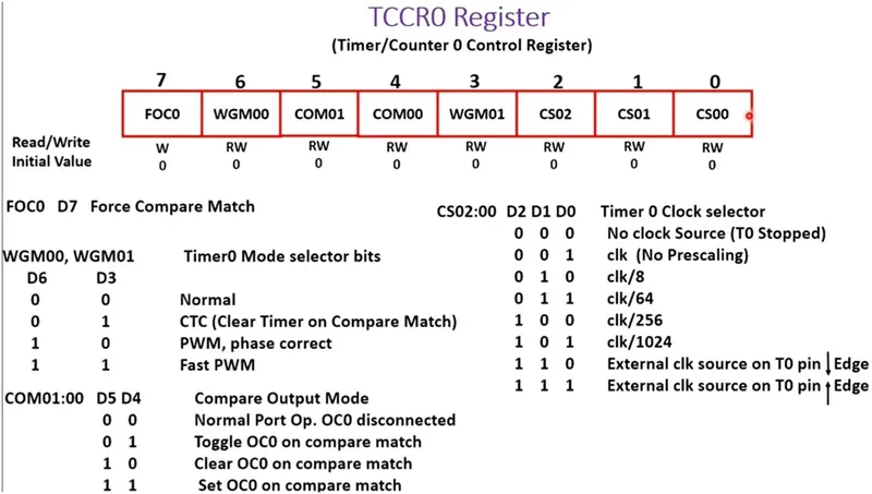
DC motor is controlled through driver L293 module. The input to driver module is from PORT A pin 0 and 1. PWM signal is fed to enable pin to control the speed of the motor. The PWM signal is generated using the timer 0. TCCR0 timer control register is declared in PWM phase correct mode and clear OC0 on compare match.
TCCR0 = 0b01100001
RESULT:
Power switch = ON, Direction switch = Clockwise, Speed = low (25% dutycycle)
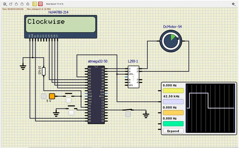
Power switch = ON, Direction switch = Clockwise, Speed = high
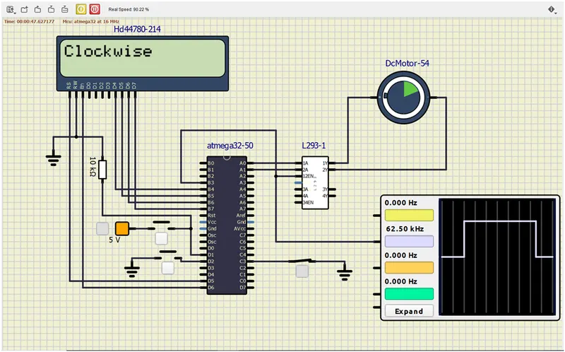
Power switch = ON, Direction switch = Anticlockwise, Speed = high