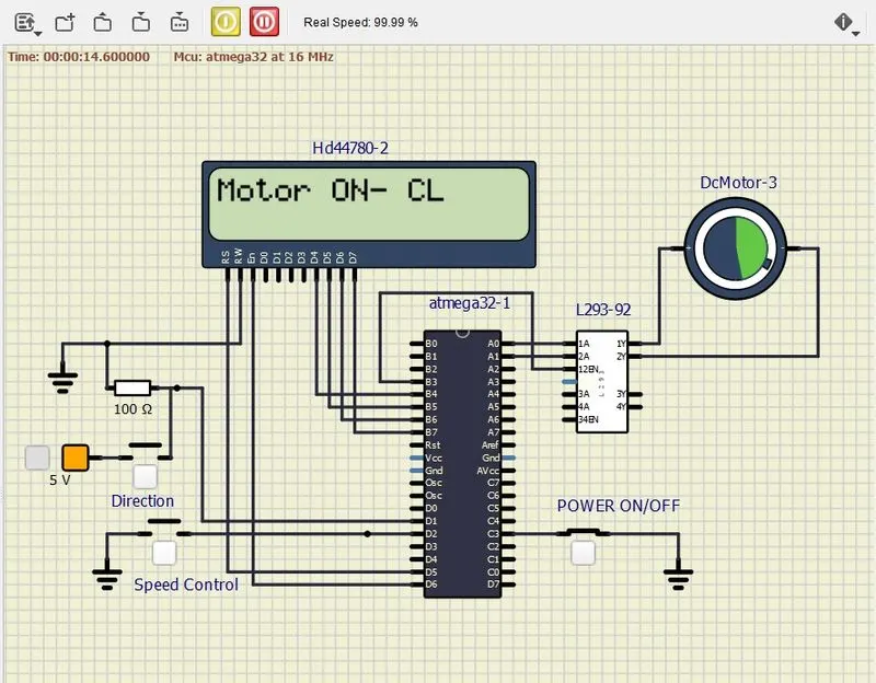
Controlling a DC motor using PWM and monitoring its Running status
AIM:
- Implement a system on the simulator for controlling a DC motor using L293 motor driver, monitor its status and print the running status of motor on the LCD Display.
Goals:
- Implement a system on simulator for Controlling the DC motor using L293 motor driver.
- Displaying the running status of DC motor on the LCD display.
Key Highlights of the Project:
- The DC motor can be controlled by using L293 motor driver.
- The speed of a DC motor can be controlled by varying its input voltage, for doing this is to use PWM (Pulse Width Modulation).
- L293D IC is a typical Motor Driver IC which allows the DC motor to drive on any direction.
Configuring Timer0 for PWM generation:
It is simple to configure PWM mode in Timer. We just need to set some bits in the TCCR0 register.
TCCR0: Timer Counter Control Register 0
Bit 7- FOC0: Force compare match
Write only bit, which can be used while generating a wave. Writing 1 to this bit will force the wave generator to act as if a compare match has occurred.
Bit 6, 3 - WGM00, WGM01: Waveform Generation Mode
|
WGM00 |
WGM01 |
Timer0 mode selection bit |
|---|---|---|
|
0 |
0 |
Normal |
|
0 |
1 |
CTC (Clear timer on Compare Match) |
|
1 |
0 |
PWM, Phase correct |
|
1 |
1 |
Fast PWM |
Bit 5:4 - COM01:00:
- When WGM00: WGM01= 11 i.e. Fast PWM. Compare Output Mode
waveform generator on OC0 pin
|
COM01 |
COM00 |
Mode Name |
Description |
|---|---|---|---|
|
0 |
0 |
Disconnected |
The normal port operation, OC0 disconnected |
|
0 |
1 |
Reserved |
Reserved |
|
1 |
0 |
Non-inverted |
Clear OC0 on compare match, set OC0 at TOP |
|
1 |
1 |
Inverted PWM |
Set OC0 on compare match, clear OC0 at TOP |
2. When WGM00: WGM01= 10 i.e. Phase correct PWM. Compare Output Mode
waveform generator on OC0 pin
|
COM01 |
COM00 |
Description |
|---|---|---|
|
0 |
0 |
The normal port operation, OC0 disconnected |
|
0 |
1 |
Reserved |
|
1 |
0 |
Clear OC0 on compare match when up-counting, set OC0 on compare match when down-counting |
|
1 |
1 |
Set OC0 on compare match when up-counting, Clear OC0 on compare match when down-counting |
Bit 2:0 - CS02:CS00: Clock Source Select
These bits are used to select a clock source. When CS02: CS00 = 000, then timer is stopped. As it gets a value between 001 to 101, it gets a clock source and starts as the timer.
|
CS02 |
CS01 |
CS00 |
Description |
|---|---|---|---|
|
0 |
0 |
0 |
No clock source (Timer / Counter stopped) |
|
0 |
0 |
1 |
clk (no pre-scaling) |
|
0 |
1 |
0 |
clk / 8 |
|
0 |
1 |
1 |
clk / 64 |
|
1 |
0 |
0 |
clk / 256 |
|
1 |
0 |
1 |
clk / 1024 |
|
1 |
1 |
0 |
External clock source on T0 pin. clock on falling edge |
|
1 |
1 |
1 |
External clock source on T0 pin. clock on rising edge. |
Fast PWM mode:
To set Fast PWM mode, we have to set WGM00: 01= 11. To generate a PWM waveform on the OC0 pin, we need to set COM01:00= 10 or 11.
COM01:00= 10 will generate Noninverting PWM output waveform and COM01:00= 11 will generate Inverting PWM output waveform.
Setting Duty cycle: we have to load value in the OCR0 register to set the duty cycle.
255 value for 100% duty cycle and 0 for 0% duty cycle. Accordingly, if we load value 127 in OCR0, the Duty cycle will be 50%.
CODE:
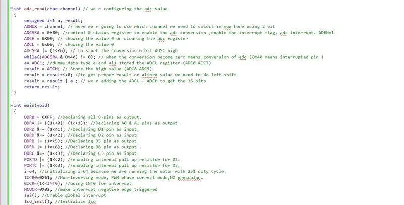
#include <avr/io.h> //we are using I/O registers of AVR
#define F_CPU 16000000L // define the crystal frequency
#include "avr/interrupt.h" // we are using external interrupt pin
#include <util/delay.h> // delay function purpose
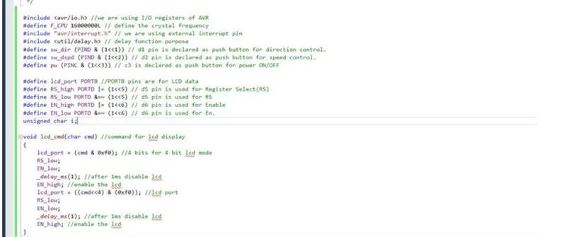
#define sw_dir (PIND & (1<<1)) // d1 pin is declared as push button for direction control.
#define sw_dspd (PIND & (1<<2)) // d2 pin is declared as push button for speed control.
#define pw (PINC & (1<<3)) // c3 is declared as push button for power ON/OFF

#define lcd_port PORTB //PORTB pins are for LCD data
#define RS_high PORTD |= (1<<5) // d5 pin is used for Register Select(RS)
#define RS_low PORTD &=~ (1<<5) // d5 pin is used for RS
#define EN_high PORTD |= (1<<6) // d6 pin is used for Enable
#define EN_low PORTD &=~ (1<<6) // d6 pin is used for En.
unsigned char i;

void lcd_cmd(char cmd) //command for lcd display
{
lcd_port = (cmd & 0xf0); //4 bits for 4 bit lcd mode
RS_low;
EN_low;
_delay_ms(1); //after 1ms disable lcd
EN_high; //enable the lcd
lcd_port = ((cmd<<4) & (0xf0)); //lcd port
RS_low;
EN_low;
_delay_ms(1); //after 1ms disable lcd
EN_high; //enable the lcd
}

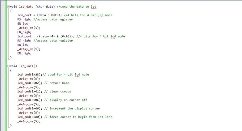
void lcd_data (char data) //send the data to lcd
{
lcd_port = (data & 0xf0); //4 bits for 4 bit lcd mode
RS_high; //access data register
EN_low;
_delay_ms(1);
EN_high;
lcd_port = ((data<<4) & (0xf0)); //4 bits for 4 bit lcd mode
RS_high; //access data register
EN_low;
_delay_ms(1);
EN_high;
}

void lcd_init()
{
lcd_cmd(0x28);// used for 4 bit lcd mode
_delay_ms(5);
lcd_cmd(0x02); // return home
_delay_ms(5);
lcd_cmd(0x01); // clear screen
_delay_ms(5);
lcd_cmd(0x0C); // display on cursor off
_delay_ms(5);
lcd_cmd(0x06); // increment the display cursor
_delay_ms(5);
lcd_cmd(0x80); // force cursor to begin from 1st line
_delay_ms(5);
}

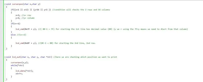
void cursorpos(char x,char y)
{
if((x<1 || x>2) || (y>16 || y<1 )) //condition will checks the 2 rows and 16 columns
{
x=1; //x= row
y=1; //y= column
}
if(x==1)
{
lcd_cmd(0x7F + y); //{ 80-1 = 7F} for starting the 1st line hex decimal value (80) {y we r using the 7F+y means we need to dtart from                                            that column}
}
else //(x==2)
{

lcd_cmd(0xBF + y); //{0C-1 = 0B} for starting the 2nd line, 2nd row.
}
}


void lcd_out(char x, char y, char *str) //here we are checking which position we want to print
{
cursorpos(x,y);
while(*str)
{
lcd_data(*str);
str++;
}
}

int adc_read(char channel) // we r configuring the adc value
{
unsigned int a, result;
ADMUX = channel; // here we r going to use which channel we need to select in mux here using 2 bit
ADCSRA = 0X80; //control & status register to enable the adc conversion ,enable the interrupt flag, adc interrupt. ADEN=1
ADCH = 0X00; // showing the value 0 or clearing the adc register
ADCL = 0x00; // showing the value 0
ADCSRA |= (1<<6); // to start the conversion 6 bit ADSC high
while((ADCSRA & 0x40) != 0); // when the conversion become zero means conversion of adc (0x40 means interrupted pin )
a= ADCL; //dummy data type a and ais stored the ADCL register (ADC0-ADC7)
result = ADCH; // Store the high value (ADC8-ADC9)
result = result<<8; //to get proper result or alined value we need to do left shift
result = result | a ; // we r adding the ADCL + ADCH to get the 16 bits
return result;
}

int main(void)
{
DDRB = 0XFF; //Declaring all 8-pins as output.
DDRA |= ((1<<0)| (1<<1)); //Declaring A0 & A1 pins as output.
DDRD &=~ (1<<1); //Declaring D1 pin as input.
DDRD &=~ (1<<2); //Declaring D2 pin as input.
DDRD |= (1<<5); //Declaring D5 pin as output.
DDRD |= (1<<6); //Declaring D6 pin as output.
DDRC &=~ (1<<3); //Declaring C3 pin as input.
PORTD |= (1<<2); //enabling internal pull up resistor for D2.
PORTC |= (1<<3); //enabling internal pull up resistor for D3.
i=64; //initializing i=64 because we are running the motor with 25% duty cycle.
TCCR0=0X61; //Non-Inverting mode, PWM phase correct mode,NO prescalar.
GICR=(1<<INT0); //using INT0 for interrupt
MCUCR=0X02; //make interrupt negative edge triggered
sei(); //Enable global interrupt
lcd_init(); //Initialize lcd

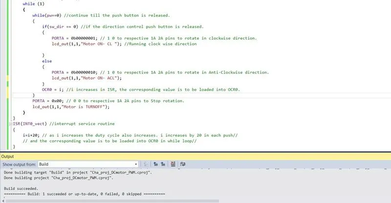
while (1)
{
while(pw==0) //continue till the push button is released.
{
if(sw_dir == 0) //if the direction control push button is released.
{
PORTA = 0b00000001; // 1 0 to respective 1A 2A pins to rotate in clockwise direction.
lcd_out(1,1,"Motor ON- CL "); //Running clock wise direction

}
else
{
PORTA = 0b00000010; // 1 0 to respective 1A 2A pins to rotate in Anti-Clockwise direction.
lcd_out(1,1,"Motor ON- ACL");

}
OCR0 = i; //i increases in ISR, the corresponding value is to be loaded into OCR0.

}

PORTA = 0x00; // 0 0 to respective 1A 2A pins to Stop rotation.
lcd_out(1,1,"Motor is TURNOFF");
}
}
ISR(INT0_vect) //interrupt service routine
{
i=i+20; // as i increases the duty cycle also increases. i increases by 20 in each push//
// and the corresponding value is to be loaded into OCR0 in while loop//
}
EXPLAINATION:
-
The code starts by including the necessary libraries and defining some constants for pin connections and configurations.
-
The
lcd_cmd,lcd_data, andlcd_initfunctions are used to send commands and data to the LCD display. These functions utilize the 4-bit mode of the LCD. -
The
cursorposfunction sets the cursor position on the LCD based on the row and column parameters. -
The
lcd_outfunction prints a string on the LCD display at the specified row and column. -
The
adc_readfunction reads the ADC value from the specified channel. It configures the ADC control and status registers and waits for the conversion to complete. -
In the
mainfunction, the data direction registers (DDRx) for the required pins are set as input or output. -
The push buttons for direction control (
sw_dir), speed control (sw_dspd), and power on/off (pw) are monitored using the PINx registers. -
The
TCCR0register is configured to enable PWM in non-inverting mode with phase-correct PWM and no prescaler. -
The
GICRandMCUCRregisters are configured to enable external interrupt INT0 on the falling edge. -
The
sei()function is called to enable global interrupts. -
The
lcd_initfunction is called to initialize the LCD display. -
Inside the while loop, the motor control is performed based on the state of the push buttons and the interrupt flag.
-
When the power button is released (
pw == 0), the motor direction is determined by the state of the direction control push button (sw_dir). -
The
OCR0register is set with the value ofito control the duty cycle of the PWM signal, which determines the motor speed. -
When the power button is pressed (
pw != 0), the motor is turned off by settingPORTAto 0x00 and the corresponding message is displayed on the LCD. -
The interrupt service routine (
ISR) is triggered when the external interrupt INT0 is detected, and it increments theivariable, increasing the duty cycle of the PWM signal.
#include

// Pin connections for L293 motor driver
const int enablePin = 9;   // PWM pin for speed control
const int in1Pin = 8;      // Control pin 1
const int in2Pin = 7;      // Control pin 2

// LCD display configuration
const int rs = 12;
const int en = 11;
const int d4 = 5;
const int d5 = 4;
const int d6 = 3;
const int d7 = 2;
LiquidCrystal lcd(rs, en, d4, d5, d6, d7);

void setup() {
  // Motor driver pin modes
  pinMode(enablePin, OUTPUT);
  pinMode(in1Pin, OUTPUT);
  pinMode(in2Pin, OUTPUT);

  // Initialize LCD display
  lcd.begin(16, 2);
  lcd.print("Motor Control");
}

void loop() {
  // Display motor status on LCD
  lcd.setCursor(0, 1);
  lcd.print("Motor: ");

  // Set motor speed and direction
  int motorSpeed = analogRead(A0) / 4;  // Read analog input for speed control (0-1023)
  int motorDirection = digitalRead(13); // Read digital input for direction control (HIGH or LOW)

  analogWrite(enablePin, motorSpeed);   // Set motor speed using PWM
  if (motorDirection == HIGH) {
    digitalWrite(in1Pin, HIGH);
    digitalWrite(in2Pin, LOW);
    lcd.print("ON ");
  } else {
    digitalWrite(in1Pin, LOW);
    digitalWrite(in2Pin, HIGH);
    lcd.print("OFF");
  }

  delay(100);
}
OUTPUT:
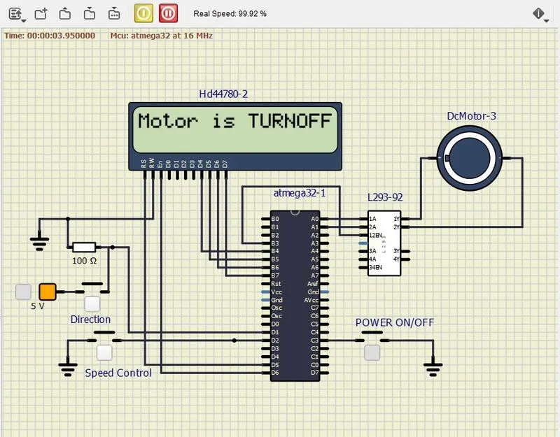
Power Switch: OFF, Direction Switch: OFF, Speed Switch: OFF :: Motor is TURN OFF Condition
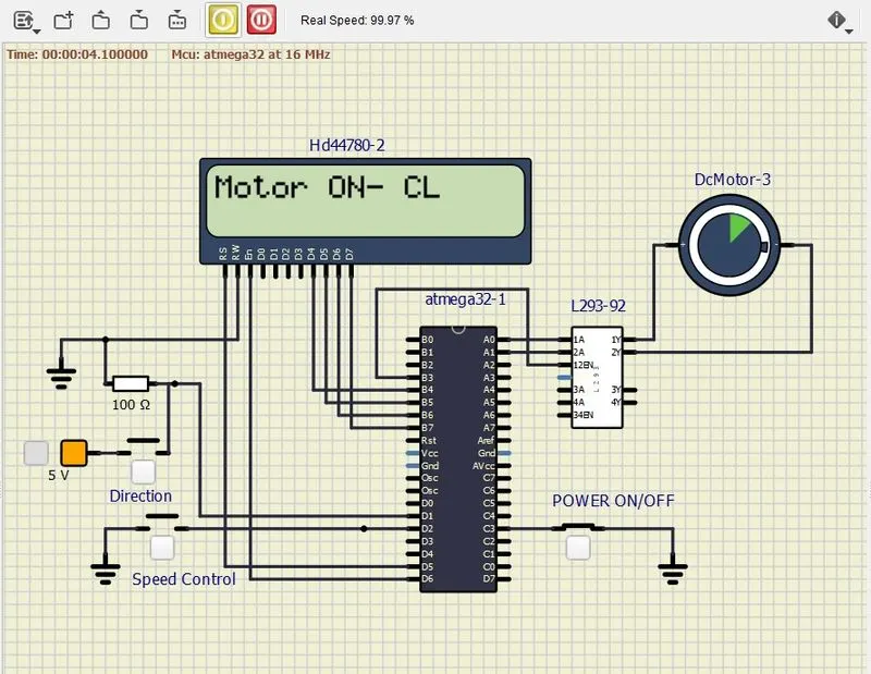
Power Switch: ON, Direction Switch: OFF, Speed Switch: OFF :: Motor is TURN ON Condition
Power Switch: ON, Direction Switch: ON, Speed Switch: OFF :: Motor is TURN ON and Direction of Rotation: REVERSE
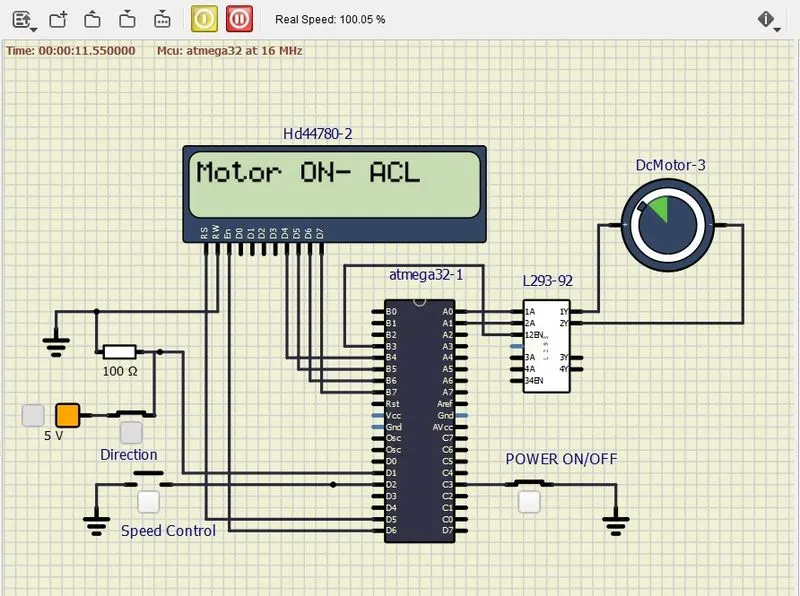
Power Switch: ON, Direction Switch: OFF, Speed Switch: ON :: Motor is TURN ON and Speed of Motor: INCREASED