Project 1_Comparative study of different storey buildings for Seismic forces
1. Project 1:
In the project 1 we need to discuss the dynamic charecteristics of the building, For the various models of the building we need to discuss the Natural time period of the buildings when the earth quake force occured on it in the X and y axis.
Factors influencing the dynamic charecteristics of a building:
- When an earth quake force is applied on the building then the building is subjected to the oscillation due to shaking of the ground or the base ment of the building and these oscillation may cause the inertia force in the building.
- The intensity and the duration of the oscillation and amount of inertia force induced in the building due to the earth quake force mainly depends on the dynamic charecteristics of the building. The dynamic charecteristics of a building is height of the building, Floor plan of the building,Location of several stiff units like lift walls or shear walls, Location or arrangement of the vertical units like columns and their connection with the foundation,Materials or mass of the structural units and connection between the columns or beams etc all these comes under the dynamic charecteristics of the building.
- In addition to these the earth quake shaking also plays an important role but it is beyond the control it depends on the natural earth quake.
- The imporatnt dynamic charecteristics is modes of the oscillation , damping generally constant at the rate of 5%. The mode of oscillation of the building is defined by the association of the natural time period and deformed natural shape which the building oscillates when the earth quake force is applied.
- Every building has more number of frquencies at which the building resists the shaking due to the earth quake force. In general the number of frequnecies of the building states that the number of modes multiplied degree of freedom at the each mode.In general there will be 6 degree of freedom for the mode of the building.In general we consider only few modes from the mode as their impact is reduced with increase in the modes.
- The frequencies with the specified deformed shape is known as natural mode of oscillation and the small frequency with largest tiime period of the building is called Fundamental natural time period (T)
- Regualr buildings held at their base from translation in three directions have two fundamental translation natural time period Tx1 and Ty1 associated with the horizontal translation oscillation in X nad Y axis and one fundamental rotaion T01 associated with the Zaxis.
Factors influencing the natural time period:
- The natural time period of building may vary based on the various parameters like height of the building, Location of the buildinhg, based on the floor plan and size of the building units like colums and beams etc.
- To get to know the various changes in the natural time period we need to develop the building models with different sizes, storeys and different building units like columns and beams etc.
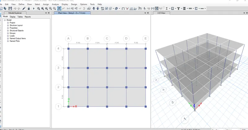
A. 2 storey building:
- The building model is developed in the e tabs soft ware by using the various tools in the soft ware.
- The soft ware is and it displays the home page and after opening the home page we need to click on the new model and after clicking on the model we need to make over the settings, units for the system(metric SI),steel section code(Indian), steel code(IS 800, 2007),Concrete code(IS 456 2000) and click on OK. Then the model will be developed and analysed by using the codes and units.
- After modifing the settings of the units and the codes of the materials now the custom grid is to be modified by editting the grid ordinates to the required number in both the X and Y axis of the plot.Here the distance between the grid ordinates in the X direction is changed to 4m and in the Y direction is changed to the 4m and after the custom storey data is to be modified that the sorey description is to be changed to plinth level, base level and the level of the storeys is to be editted that the storey height is to be either 3m mentioned in the description details or some times the storey height is editted.Here the plinth level is changed to 2.2m and the storey height is changed to 3m.
- After that the required number of the storeys is to be added and they similar to property is to be changed to none if there is no similarity and if there is any similarities in the storeys of the building then the reference storey is to be modified in the remaining storey.and click on OK then the grid of the building layout is displayed in the home page of the model of the building.
- After the modification of the custom grid now click on the define tool bar and select the material properties in the options given and change the material grade, standard ets and then click on the OK, So first we need to ad the material concrete and change the standard to the INDIAN , grade of the concrete to the M30 and concrete code to the IS 456: 2000 and click on OK and now add the material and now change the material in to steel and cahnge the grade to the HYSD bars and the code to the IS 800:2007 and click on the OK option.
- Now the sectional properties of the building units like column and the beam are created. Now the click on the define tool bar and select the section properties and select the add section and select the beam section and edit the name of the property as for the beam B300x400 and click on the property modifiers and change the moment of inertia of the X and Y axis, For the seimic load the moment of inertia is generally taken to the limit of the 35% and this is done to the ultimate loading condition but for the nominal analysis of the building the moment of inertia is to be considered to its full limit and click on OK.
- Now again click on the define and select the section properties and create the column unit of the building and the size of the column is to be about C 400x400 and again change the property modifier also as we done in the case of the building beam.
- Now again select the section property and select the slab section and the property of the slab is changed to Slab 150 and the modelling type is changed to the membrane an click on the OK.
- Now Click on the define tool bar and select the load pattern and add the loads i.e live load, wall as super dead load, seismic load EQX,EQY and the change the zone type and soil factor.
- Now again select the define tool bar and change the mass source data that the dead load is 100% and the live load is 25% and the super dead load is 100%.
- Now check the load cases that all the loads is to be included and the load combinations of the various loadings on the building unit.
- Now the modelling of the building is to be done using the options in the left side of the window and now select the quick column option change the property of the column to which we require and the columns is placed in the grid points that the storey stage is selected a all storey in the right side of the window, then only the column is developed in all the storeys.
- The columns may be placed either individually or by using the replicate option in the grid option.
- The beam is also developed in the same way as that of the column, select the quick beam optio nand change the property to the beam which we require the specification.
- THe slab is also placed as that of like the previous, Now select th quick slab option and select the slab property as that of slab150 and based on the boundry of the grids and the column beam position the slab assigned.
- Now using the select option select all the beams of the building and click on the assign option in the ribbon and select the frame loads and select the distributed frame loads and add the load of the walls as 10kn/m and click on OK then the load is assigned to the beams.
- Now using the select option select slab sections and select the slab 150 of the building and click on the assign option in the ribbon and select the shell loads and select the distributed shell loads and add the load of the walls as 3kn/m and click on OK then the load is assigned to all the slabs.
- Now using the select option select slab sections and select the slab 150 of the building and click on the assign option in the ribbon and select the shells and select the diaphram and click on the ok then the centre of the mass of the floor is assigned to the building.
- After that the click on the analysis option in the ribbon, to analyse the building the model is to be saved with specific file name.
-
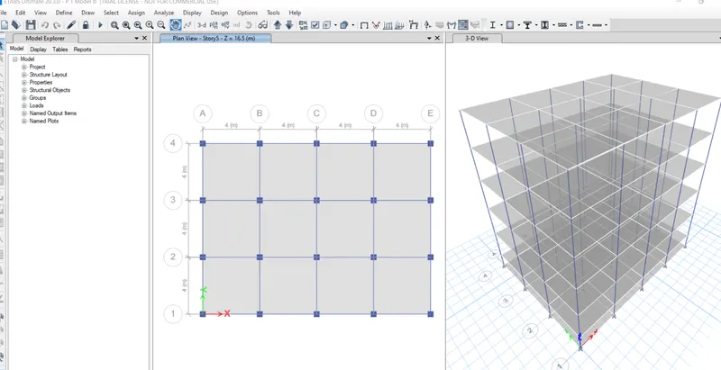
B. Bench mark 5 storey building:
- The building model is developed in the e tabs soft ware by using the various tools in the soft ware.
- The soft ware is and it displays the home page and after opening the home page we need to click on the new model and after clicking on the model we need to make over the settings, units for the system(metric SI),steel section code(Indian), steel code(IS 800, 2007),Concrete code(IS 456 2000) and click on OK. Then the model will be developed and analysed by using the codes and units.
- After modifing the settings of the units and the codes of the materials now the custom grid is to be modified by editting the grid ordinates to the required number in both the X and Y axis of the plot.Here the distance between the grid ordinates in the X direction is changed to 4m and in the Y direction is changed to the 4m and after the custom storey data is to be modified that the sorey description is to be changed to plinth level, base level and the level of the storeys is to be editted that the storey height is to be either 3m mentioned in the description details or some times the storey height is editted.Here the plinth level is changed to 2.2m and the storey height is changed to 3m.
- After that the required number of the storeys i.e 5 no of stories is to be added and they similar to property is to be changed to none if there is no similarity and if there is any similarities in the storeys of the building then the reference storey is to be modified in the remaining storey.and click on OK then the grid of the building layout is displayed in the home page of the model of the building.
- After the modification of the custom grid now click on the define tool bar and select the material properties in the options given and change the material grade, standard ets and then click on the OK, So first we need to ad the material concrete and change the standard to the INDIAN , grade of the concrete to the M30 and concrete code to the IS 456: 2000 and click on OK and now add the material and now change the material in to steel and cahnge the grade to the HYSD bars and the code to the IS 800:2007 and click on the OK option.
- Now the sectional properties of the building units like column and the beam are created. Now the click on the define tool bar and select the section properties and select the add section and select the beam section and edit the name of the property as for the beam B300x400 and click on the property modifiers and change the moment of inertia of the X and Y axis, For the seimic load the moment of inertia is generally taken to the limit of the 35% and this is done to the ultimate loading condition but for the nominal analysis of the building the moment of inertia is to be considered to its full limit and click on OK.
- Now again click on the define and select the section properties and create the column unit of the building and the size of the column is to be about C 400x400 and again change the property modifier also as we done in the case of the building beam.
- Now again select the section property and select the slab section and the property of the slab is changed to Slab 150 and the modelling type is changed to the membrane an click on the OK.
- Now Click on the define tool bar and select the load pattern and add the loads i.e live load, wall as super dead load, seismic load EQX,EQY and the change the zone type and soil factor.
- Now again select the define tool bar and change the mass source data that the dead load is 100% and the live load is 25% and the super dead load is 100%.
- Now check the load cases that all the loads is to be included and the load combinations of the various loadings on the building unit.
- Now the modelling of the building is to be done using the options in the left side of the window and now select the quick column option change the property of the column to which we require and the columns is placed in the grid points that the storey stage is selected a all storey in the right side of the window, then only the column is developed in all the storeys.
- The columns may be placed either individually or by using the replicate option in the grid option.
- The beam is also developed in the same way as that of the column, select the quick beam optio nand change the property to the beam which we require the specification.
- THe slab is also placed as that of like the previous, Now select th quick slab option and select the slab property as that of slab150 and based on the boundry of the grids and the column beam position the slab assigned.
- Now using the select option select all the beams of the building and click on the assign option in the ribbon and select the frame loads and select the distributed frame loads and add the load of the walls as 10kn/m and click on OK then the load is assigned to the beams.
- Now using the select option select slab sections and select the slab 150 of the building and click on the assign option in the ribbon and select the shell loads and select the distributed shell loads and add the load of the walls as 3kn/m and click on OK then the load is assigned to all the slabs.
- Now using the select option select slab sections and select the slab 150 of the building and click on the assign option in the ribbon and select the shells and select the diaphram and click on the ok then the centre of the mass of the floor is assigned to the building.
- After that the click on the analysis option in the ribbon, to analyse the building the model is to be saved with specific file name.
-
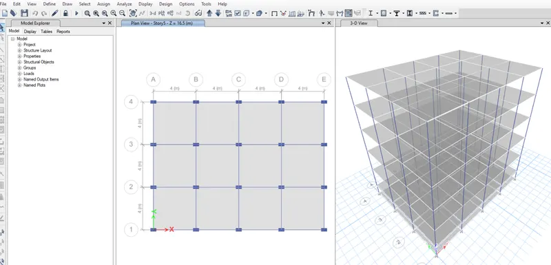
C. Benchmark building rectangular columns oriented along X direction:
- The building model is developed in the e tabs soft ware by using the various tools in the soft ware.
- The soft ware is and it displays the home page and after opening the home page we need to click on the new model and after clicking on the model we need to make over the settings, units for the system(metric SI),steel section code(Indian), steel code(IS 800, 2007),Concrete code(IS 456 2000) and click on OK. Then the model will be developed and analysed by using the codes and units.
- After modifing the settings of the units and the codes of the materials now the custom grid is to be modified by editting the grid ordinates to the required number in both the X and Y axis of the plot.Here the distance between the grid ordinates in the X direction is changed to 4m and in the Y direction is changed to the 4m and after the custom storey data is to be modified that the sorey description is to be changed to plinth level, base level and the level of the storeys is to be editted that the storey height is to be either 3m mentioned in the description details or some times the storey height is editted.Here the plinth level is changed to 2.2m and the storey height is changed to 3m.
- After that the required number of the storeys i.e 5 no of stories is to be added and they similar to property is to be changed to none if there is no similarity and if there is any similarities in the storeys of the building then the reference storey is to be modified in the remaining storey.and click on OK then the grid of the building layout is displayed in the home page of the model of the building.
- After the modification of the custom grid now click on the define tool bar and select the material properties in the options given and change the material grade, standard ets and then click on the OK, So first we need to ad the material concrete and change the standard to the INDIAN , grade of the concrete to the M30 and concrete code to the IS 456: 2000 and click on OK and now add the material and now change the material in to steel and cahnge the grade to the HYSD bars and the code to the IS 800:2007 and click on the OK option.
- Now the sectional properties of the building units like column and the beam are created. Now the click on the define tool bar and select the section properties and select the add section and select the beam section and edit the name of the property as for the beam B300x400 and click on the property modifiers and change the moment of inertia of the X and Y axis, For the seimic load the moment of inertia is generally taken to the limit of the 35% and this is done to the ultimate loading condition but for the nominal analysis of the building the moment of inertia is to be considered to its full limit and click on OK.
- Now again click on the define and select the section properties and create the column unit of the building and the size of the column is to be about C 550x300 and again change the property modifier also as we done in the case of the building beam.
- Now again select the section property and select the slab section and the property of the slab is changed to Slab 150 and the modelling type is changed to the membrane an click on the OK.
- Now Click on the define tool bar and select the load pattern and add the loads i.e live load, wall as super dead load, seismic load EQX,EQY and the change the zone type and soil factor.
- Now again select the define tool bar and change the mass source data that the dead load is 100% and the live load is 25% and the super dead load is 100%.
- Now check the load cases that all the loads is to be included and the load combinations of the various loadings on the building unit.
- Now the modelling of the building is to be done using the options in the left side of the window and now select the quick column option change the property of the column to which we require and the columns is placed in the grid points that the storey stage is selected a all storey in the right side of the window, then only the column is developed in all the storeys.
- The columns may be placed either individually or by using the replicate option in the grid option.
- The beam is also developed in the same way as that of the column, select the quick beam optio nand change the property to the beam which we require the specification.
- THe slab is also placed as that of like the previous, Now select th quick slab option and select the slab property as that of slab150 and based on the boundry of the grids and the column beam position the slab assigned.
- Now using the select option select all the beams of the building and click on the assign option in the ribbon and select the frame loads and select the distributed frame loads and add the load of the walls as 10kn/m and click on OK then the load is assigned to the beams.
- Now using the select option select slab sections and select the slab 150 of the building and click on the assign option in the ribbon and select the shell loads and select the distributed shell loads and add the load of the walls as 3kn/m and click on OK then the load is assigned to all the slabs.
- Now using the select option select slab sections and select the slab 150 of the building and click on the assign option in the ribbon and select the shells and select the diaphram and click on the ok then the centre of the mass of the floor is assigned to the building.
- After that the click on the analysis option in the ribbon, to analyse the building the model is to be saved with specific file name.
-
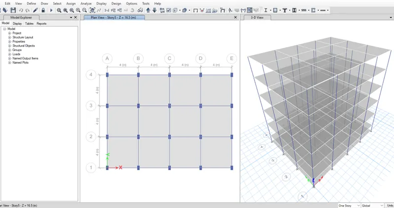
D. Benchmark building rectangular columns oriented along Y direction:
- The building model D is same as that of the building model C but the only difference is the orientation of the columns so we can modify the orientation of the columns building model C to create the building model D.
- The building model C is saved as another name like Building model D and the orientation of the columns is changed.
- Now click on the select in the ribbon tool bar and select the frame sections and select the columns then all the columns are selected .
- Now click on the assign option in the ribbon tool bar and select the local axes and change the orientation angle to 90 then the columns 550x300 is changed to the columns with 300x550.
- After that the click on the analysis option in the ribbon, to analyse the building the model is to be saved with specific file name.
E. 10 Storey building with the various column size along the building height:
- The building model is developed in the e tabs soft ware by using the various tools in the soft ware.
- The soft ware is and it displays the home page and after opening the home page we need to click on the new model and after clicking on the model we need to make over the settings, units for the system(metric SI),steel section code(Indian), steel code(IS 800, 2007),Concrete code(IS 456 2000) and click on OK. Then the model will be developed and analysed by using the codes and units.
- After modifing the settings of the units and the codes of the materials now the custom grid is to be modified by editting the grid ordinates to the required number in both the X and Y axis of the plot.Here the distance between the grid ordinates in the X direction is changed to 4m and in the Y direction is changed to the 4m and after the custom storey data is to be modified that the sorey description is to be changed to plinth level, base level and the level of the storeys is to be editted that the storey height is to be either 3m mentioned in the description details or some times the storey height is editted.Here the plinth level is changed to 2.2m and the storey height is changed to 3m.
- After that the required number of the storeys i.e 10 no of stories is to be added and they similar to property is to be changed to none if there is no similarity and if there is any similarities in the storeys of the building then the reference storey is to be modified in the remaining storey.and click on OK then the grid of the building layout is displayed in the home page of the model of the building.
- After the modification of the custom grid now click on the define tool bar and select the material properties in the options given and change the material grade, standard ets and then click on the OK, So first we need to ad the material concrete and change the standard to the INDIAN , grade of the concrete to the M30 and concrete code to the IS 456: 2000 and click on OK and now add the material and now change the material in to steel and cahnge the grade to the HYSD bars and the code to the IS 800:2007 and click on the OK option.
- Now the sectional properties of the building units like column and the beam are created. Now the click on the define tool bar and select the section properties and select the add section and select the beam section and edit the name of the property as for the beam B300x400 and click on the property modifiers and change the moment of inertia of the X and Y axis, For the seimic load the moment of inertia is generally taken to the limit of the 35% and this is done to the ultimate loading condition but for the nominal analysis of the building the moment of inertia is to be considered to its full limit and click on OK.
- Now the building model has columns of size 400x400 and 600x600. click on the define and select the section properties and create the column unit of the building and the size of the column is to be about C 400x400 and again change the property modifier also as we done in the case of the building beam and again repeat the procedure and create the column of size 600x600.
- Click on the tick mark on the ribbon bar and the beams and the floors are unmarked and now click on the view option and select the building view limits that is storey 5 to storey 10.Now slect the columns and click on the assign option and now select the column 400x 400 then the top floor columns are modified.
- Now again select the section property and select the slab section and the property of the slab is changed to Slab 150 and the modelling type is changed to the membrane an click on the OK.
- Now Click on the define tool bar and select the load pattern and add the loads i.e live load, wall as super dead load, seismic load EQX,EQY and the change the zone type and soil factor.
- Now again select the define tool bar and change the mass source data that the dead load is 100% and the live load is 25% and the super dead load is 100%.
- Now check the load cases that all the loads is to be included and the load combinations of the various loadings on the building unit.
- Now the modelling of the building is to be done using the options in the left side of the window and now select the quick column option change the property of the column to which we require and the columns is placed in the grid points that the storey stage is selected a all storey in the right side of the window, then only the column is developed in all the storeys.
- The columns may be placed either individually or by using the replicate option in the grid option.
- The beam is also developed in the same way as that of the column, select the quick beam optio nand change the property to the beam which we require the specification.
- THe slab is also placed as that of like the previous, Now select th quick slab option and select the slab property as that of slab150 and based on the boundry of the grids and the column beam position the slab assigned.
- Now using the select option select all the beams of the building and click on the assign option in the ribbon and select the frame loads and select the distributed frame loads and add the load of the walls as 10kn/m and click on OK then the load is assigned to the beams.
- Now using the select option select slab sections and select the slab 150 of the building and click on the assign option in the ribbon and select the shell loads and select the distributed shell loads and add the load of the walls as 3kn/m and click on OK then the load is assigned to all the slabs.
- Now using the select option select slab sections and select the slab 150 of the building and click on the assign option in the ribbon and select the shells and select the diaphram and click on the ok then the centre of the mass of the floor is assigned to the building.
- After that the click on the analysis option in the ribbon, to analyse the building the model is to be saved with specific file name.
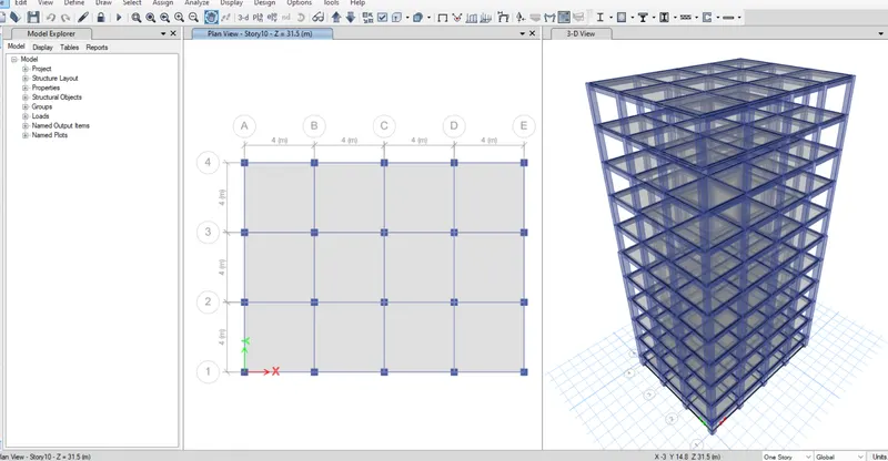
F. 10storey building with column size 600x600:
- The building model is developed in the e tabs soft ware by using the various tools in the soft ware.
- The soft ware is and it displays the home page and after opening the home page we need to click on the new model and after clicking on the model we need to make over the settings, units for the system(metric SI),steel section code(Indian), steel code(IS 800, 2007),Concrete code(IS 456 2000) and click on OK. Then the model will be developed and analysed by using the codes and units.
- After modifing the settings of the units and the codes of the materials now the custom grid is to be modified by editting the grid ordinates to the required number in both the X and Y axis of the plot.Here the distance between the grid ordinates in the X direction is changed to 4m and in the Y direction is changed to the 4m and after the custom storey data is to be modified that the sorey description is to be changed to plinth level, base level and the level of the storeys is to be editted that the storey height is to be either 3m mentioned in the description details or some times the storey height is editted.Here the plinth level is changed to 2.2m and the storey height is changed to 3m.
- After that the required number of the storeys i.e 10 no of stories is to be added and they similar to property is to be changed to none if there is no similarity and if there is any similarities in the storeys of the building then the reference storey is to be modified in the remaining storey.and click on OK then the grid of the building layout is displayed in the home page of the model of the building.
- After the modification of the custom grid now click on the define tool bar and select the material properties in the options given and change the material grade, standard ets and then click on the OK, So first we need to ad the material concrete and change the standard to the INDIAN , grade of the concrete to the M30 and concrete code to the IS 456: 2000 and click on OK and now add the material and now change the material in to steel and cahnge the grade to the HYSD bars and the code to the IS 800:2007 and click on the OK option.
- Now the sectional properties of the building units like column and the beam are created. Now the click on the define tool bar and select the section properties and select the add section and select the beam section and edit the name of the property as for the beam B300x400 and click on the property modifiers and change the moment of inertia of the X and Y axis, For the seimic load the moment of inertia is generally taken to the limit of the 35% and this is done to the ultimate loading condition but for the nominal analysis of the building the moment of inertia is to be considered to its full limit and click on OK.
- Now again click on the define and select the section properties and create the column unit of the building and the size of the column is to be about C 600x600 and again change the property modifier also as we done in the case of the building beam.
- Now again select the section property and select the slab section and the property of the slab is changed to Slab 150 and the modelling type is changed to the membrane an click on the OK.
- Now Click on the define tool bar and select the load pattern and add the loads i.e live load, wall as super dead load, seismic load EQX,EQY and the change the zone type and soil factor.
- Now again select the define tool bar and change the mass source data that the dead load is 100% and the live load is 25% and the super dead load is 100%.
- Now check the load cases that all the loads is to be included and the load combinations of the various loadings on the building unit.
- Now the modelling of the building is to be done using the options in the left side of the window and now select the quick column option change the property of the column to which we require and the columns is placed in the grid points that the storey stage is selected a all storey in the right side of the window, then only the column is developed in all the storeys.
- The columns may be placed either individually or by using the replicate option in the grid option.
- The beam is also developed in the same way as that of the column, select the quick beam optio nand change the property to the beam which we require the specification.
- THe slab is also placed as that of like the previous, Now select th quick slab option and select the slab property as that of slab150 and based on the boundry of the grids and the column beam position the slab assigned.
- Now using the select option select all the beams of the building and click on the assign option in the ribbon and select the frame loads and select the distributed frame loads and add the load of the walls as 10kn/m and click on OK then the load is assigned to the beams.
- Now using the select option select slab sections and select the slab 150 of the building and click on the assign option in the ribbon and select the shell loads and select the distributed shell loads and add the load of the walls as 3kn/m and click on OK then the load is assigned to all the slabs.
- Now using the select option select slab sections and select the slab 150 of the building and click on the assign option in the ribbon and select the shells and select the diaphram and click on the ok then the centre of the mass of the floor is assigned to the building.
- After that the click on the analysis option in the ribbon, to analyse the building the model is to be saved with specific file name.
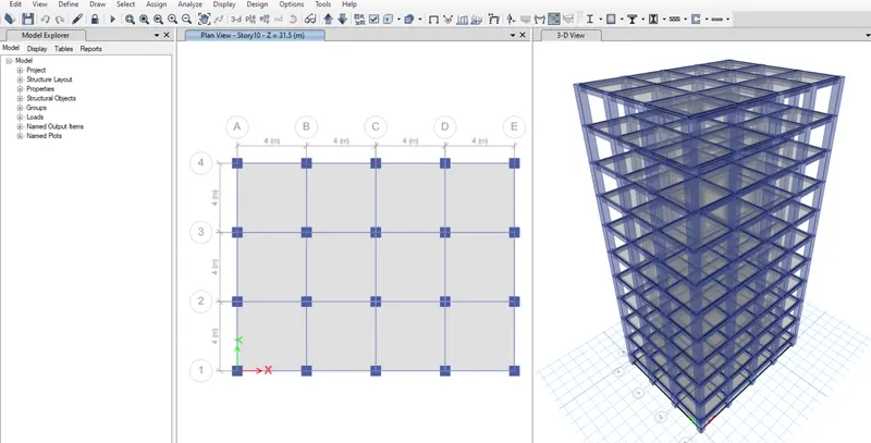
G. 25 storey building with varying column height along the building height:
- The building model is developed in the e tabs soft ware by using the various tools in the soft ware.
- The soft ware is and it displays the home page and after opening the home page we need to click on the new model and after clicking on the model we need to make over the settings, units for the system(metric SI),steel section code(Indian), steel code(IS 800, 2007),Concrete code(IS 456 2000) and click on OK. Then the model will be developed and analysed by using the codes and units.
- After modifing the settings of the units and the codes of the materials now the custom grid is to be modified by editting the grid ordinates to the required number in both the X and Y axis of the plot.Here the distance between the grid ordinates in the X direction is changed to 4m and in the Y direction is changed to the 4m and after the custom storey data is to be modified that the sorey description is to be changed to plinth level, base level and the level of the storeys is to be editted that the storey height is to be either 3m mentioned in the description details or some times the storey height is editted.Here the plinth level is changed to 2.2m and the storey height is changed to 3m.
- After that the required number of the storeys i.e 25 no of stories is to be added and they similar to property is to be changed to none if there is no similarity and if there is any similarities in the storeys of the building then the reference storey is to be modified in the remaining storey.and click on OK then the grid of the building layout is displayed in the home page of the model of the building.
- After the modification of the custom grid now click on the define tool bar and select the material properties in the options given and change the material grade, standard ets and then click on the OK, So first we need to ad the material concrete and change the standard to the INDIAN , grade of the concrete to the M30 and concrete code to the IS 456: 2000 and click on OK and now add the material and now change the material in to steel and cahnge the grade to the HYSD bars and the code to the IS 800:2007 and click on the OK option.
- Now the sectional properties of the building units like column and the beam are created. Now the click on the define tool bar and select the section properties and select the add section and select the beam section and edit the name of the property as for the beam B300x400 and click on the property modifiers and change the moment of inertia of the X and Y axis, For the seimic load the moment of inertia is generally taken to the limit of the 35% and this is done to the ultimate loading condition but for the nominal analysis of the building the moment of inertia is to be considered to its full limit and click on OK.
- Now the building model has columns of size 400x400 ,600x600,800x800. click on the define and select the section properties and create the column unit of the building and the size of the column is to be about C 400x400 and again change the property modifier also as we done in the case of the building beam and again repeat the procedure and create the column of size 600x600 and as well as 800x800.
- Click on the tick mark on the ribbon bar and the beams and the floors are unmarked and now click on the view option and select the building view limits that is storey 25 to storey 21.Now slect the columns and click on the assign option and now select the column 400x 400 then the top floor columns are modified and in the same way the cloumn sizes are modified to 600x600 for the middle 10 storeys and 800x800 to the bottom storeys.
- Now again select the section property and select the slab section and the property of the slab is changed to Slab 150 and the modelling type is changed to the membrane an click on the OK.
- Now Click on the define tool bar and select the load pattern and add the loads i.e live load, wall as super dead load, seismic load EQX,EQY and the change the zone type and soil factor.
- Now again select the define tool bar and change the mass source data that the dead load is 100% and the live load is 25% and the super dead load is 100%.
- Now check the load cases that all the loads is to be included and the load combinations of the various loadings on the building unit.
- Now the modelling of the building is to be done using the options in the left side of the window and now select the quick column option change the property of the column to which we require and the columns is placed in the grid points that the storey stage is selected a all storey in the right side of the window, then only the column is developed in all the storeys.
- The columns may be placed either individually or by using the replicate option in the grid option.
- The beam is also developed in the same way as that of the column, select the quick beam optio nand change the property to the beam which we require the specification.
- THe slab is also placed as that of like the previous, Now select th quick slab option and select the slab property as that of slab150 and based on the boundry of the grids and the column beam position the slab assigned.
- Now using the select option select all the beams of the building and click on the assign option in the ribbon and select the frame loads and select the distributed frame loads and add the load of the walls as 10kn/m and click on OK then the load is assigned to the beams.
- Now using the select option select slab sections and select the slab 150 of the building and click on the assign option in the ribbon and select the shell loads and select the distributed shell loads and add the load of the walls as 3kn/m and click on OK then the load is assigned to all the slabs.
- Now using the select option select slab sections and select the slab 150 of the building and click on the assign option in the ribbon and select the shells and select the diaphram and click on the ok then the centre of the mass of the floor is assigned to the building.
- After that the click on the analysis option in the ribbon, to analyse the building the model is to be saved with specific file name.
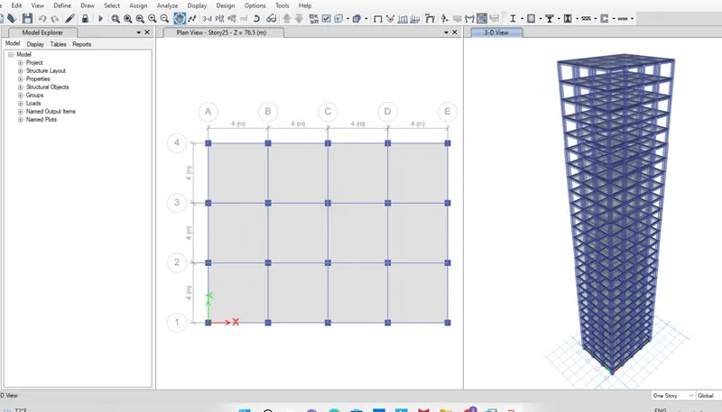
H. 25storey building with column size 800x800:
- The building model is developed in the e tabs soft ware by using the various tools in the soft ware.
- The soft ware is and it displays the home page and after opening the home page we need to click on the new model and after clicking on the model we need to make over the settings, units for the system(metric SI),steel section code(Indian), steel code(IS 800, 2007),Concrete code(IS 456 2000) and click on OK. Then the model will be developed and analysed by using the codes and units.
- After modifing the settings of the units and the codes of the materials now the custom grid is to be modified by editting the grid ordinates to the required number in both the X and Y axis of the plot.Here the distance between the grid ordinates in the X direction is changed to 4m and in the Y direction is changed to the 4m and after the custom storey data is to be modified that the sorey description is to be changed to plinth level, base level and the level of the storeys is to be editted that the storey height is to be either 3m mentioned in the description details or some times the storey height is editted.Here the plinth level is changed to 2.2m and the storey height is changed to 3m.
- After that the required number of the storeys i.e 25 no of stories is to be added and they similar to property is to be changed to none if there is no similarity and if there is any similarities in the storeys of the building then the reference storey is to be modified in the remaining storey.and click on OK then the grid of the building layout is displayed in the home page of the model of the building.
- After the modification of the custom grid now click on the define tool bar and select the material properties in the options given and change the material grade, standard ets and then click on the OK, So first we need to ad the material concrete and change the standard to the INDIAN , grade of the concrete to the M30 and concrete code to the IS 456: 2000 and click on OK and now add the material and now change the material in to steel and cahnge the grade to the HYSD bars and the code to the IS 800:2007 and click on the OK option.
- Now the sectional properties of the building units like column and the beam are created. Now the click on the define tool bar and select the section properties and select the add section and select the beam section and edit the name of the property as for the beam B300x400 and click on the property modifiers and change the moment of inertia of the X and Y axis, For the seimic load the moment of inertia is generally taken to the limit of the 35% and this is done to the ultimate loading condition but for the nominal analysis of the building the moment of inertia is to be considered to its full limit and click on OK.
- Now again click on the define and select the section properties and create the column unit of the building and the size of the column is to be about C 800x800 and again change the property modifier also as we done in the case of the building beam.
- Now again select the section property and select the slab section and the property of the slab is changed to Slab 150 and the modelling type is changed to the membrane an click on the OK.
- Now Click on the define tool bar and select the load pattern and add the loads i.e live load, wall as super dead load, seismic load EQX,EQY and the change the zone type and soil factor.
- Now again select the define tool bar and change the mass source data that the dead load is 100% and the live load is 25% and the super dead load is 100%.
- Now check the load cases that all the loads is to be included and the load combinations of the various loadings on the building unit.
- Now the modelling of the building is to be done using the options in the left side of the window and now select the quick column option change the property of the column to which we require and the columns is placed in the grid points that the storey stage is selected a all storey in the right side of the window, then only the column is developed in all the storeys.
- The columns may be placed either individually or by using the replicate option in the grid option.
- The beam is also developed in the same way as that of the column, select the quick beam optio nand change the property to the beam which we require the specification.
- THe slab is also placed as that of like the previous, Now select th quick slab option and select the slab property as that of slab150 and based on the boundry of the grids and the column beam position the slab assigned.
- Now using the select option select all the beams of the building and click on the assign option in the ribbon and select the frame loads and select the distributed frame loads and add the load of the walls as 10kn/m and click on OK then the load is assigned to the beams.
- Now using the select option select slab sections and select the slab 150 of the building and click on the assign option in the ribbon and select the shell loads and select the distributed shell loads and add the load of the walls as 3kn/m and click on OK then the load is assigned to all the slabs.
- Now using the select option select slab sections and select the slab 150 of the building and click on the assign option in the ribbon and select the shells and select the diaphram and click on the ok then the centre of the mass of the floor is assigned to the building.
- After that the click on the analysis option in the ribbon, to analyse the building the model is to be saved with specific file name.
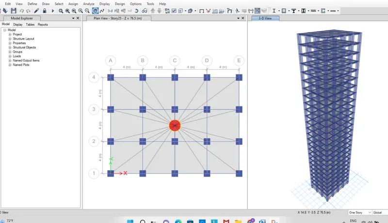
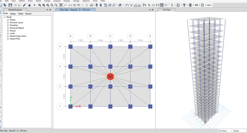
J.25 storey building with the imposed mass 10% greater than building model H :
- The building model J is same as that of the building model H but the only difference is the increase in the imposed mass to 10% by the imposed mass in the building model H.
- The building model H is saved as another name like Building model J and the imposed mass is increased by the 10%.
- Now using the select option select slab sections and select the slab 150 of the building and click on the assign option in the ribbon and select the shell loads and select the distributed shell loads and add the load of the walls as 3.3kn/m and click on OK then the load is assigned to all the slabs.So the building model J is modified with the imposed mass
- After that the click on the analysis option in the ribbon, to analyse the building the model is to be saved with specific file name.
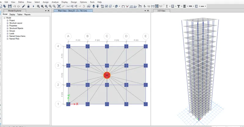
K.25 storey building with the imposed mass 20% greater than building model H :
- The building model J is same as that of the building model H but the only difference is the increase in the imposed mass to 20% by the imposed mass in the building model H.
- The building model H is saved as another name like Building model J and the imposed mass is increased by the 20%.
- Now using the select option select slab sections and select the slab 150 of the building and click on the assign option in the ribbon and select the shell loads and select the distributed shell loads and add the load of the walls as 3.6kn/m and click on OK then the load is assigned to all the slabs.So the building model J is modified with the imposed mass
- After that the click on the analysis option in the ribbon, to analyse the building the model is to be saved with specific file name.
Factors influencing the natural time period of the building:
- Effect of stiffness on the natural time period of the building:
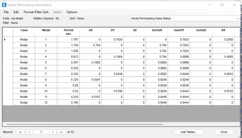
Modal participating mass ratio for the building model E:
Modal participating mass ratio for the building model F:
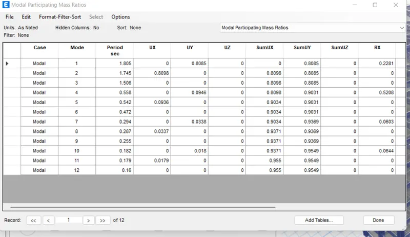
In the above building models E and F we can conclude that the natural time period for the building model E is slighlty lower than the natural time period for the building model F i.e for the building model E it is about 78% of mass participation in X and Y axis where as 80% of mass participation in X and Y axis for the building model F. In the building model F there is only one size of the columns when compared to the building model E, the building model F is more stiff than the building model E, so the fundamental time period is more for the building with the more stiffness.
Modal participating mass ratio for the building model G:
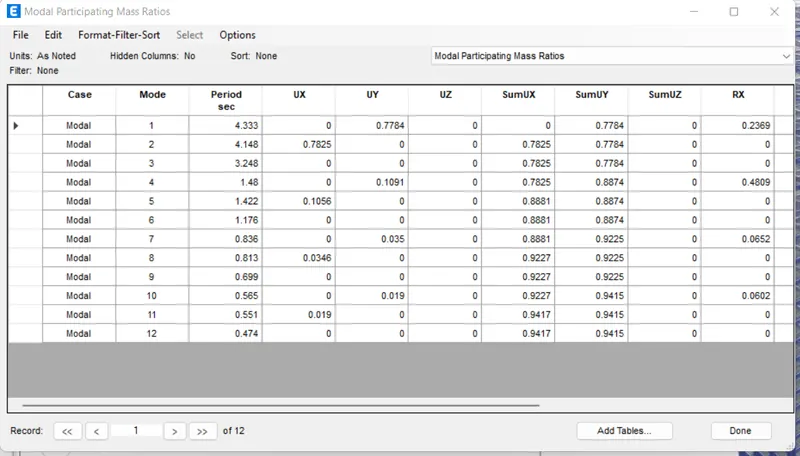
Modal participating mass ratio for the building model H:
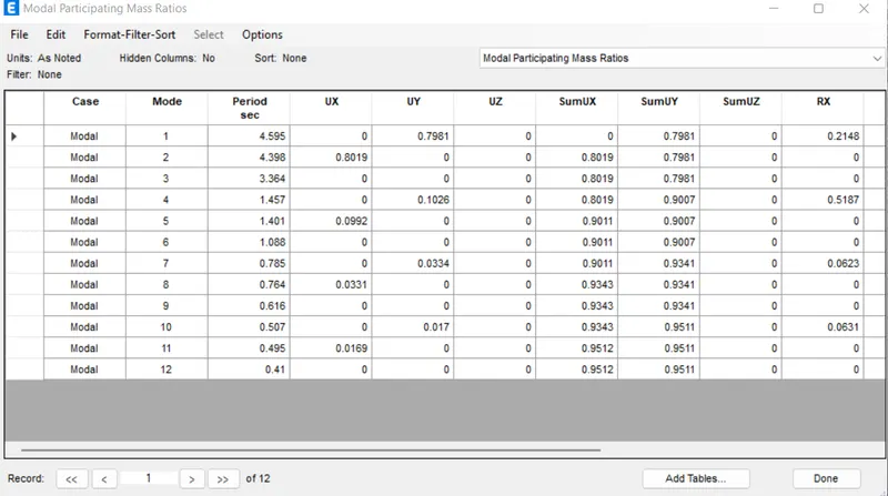
In the above building models G and H we can conclude that the natural time period for the building model G is slighlty lower than the natural time period for the building model H i.e for the building model G it is about 77 to 78% of mass participation in X and Y axis where as 80% of mass participation in X and Y axis for the building model H. In the building model H there is only one size of the columns when compared to the building model G, the building model H is more stiff than the building model E, so the fundamental time period is more for the building with the more stiffness.
- Effect of mass on the Time period:
Modal participating mass ratio for the building model H:
Modal participating mass ratio for the building model J:
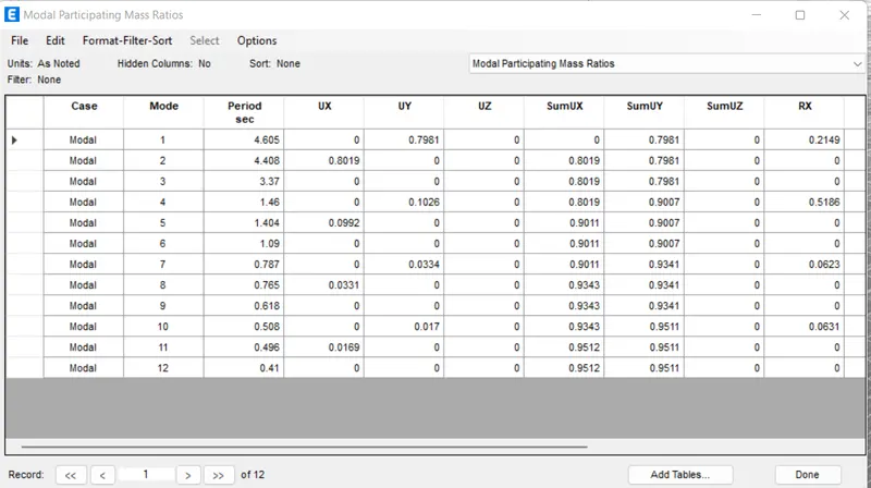
Modal participating mass ratio for the building model K:
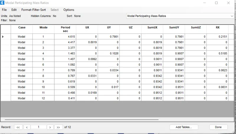
All the three building models H,J,K are of same number of storeys with the same height but in the model J the imposed load is greater than 10% where as in the model K the imposed load is greater than 20%.However the time period is for the building model K is more when compare to the building models H and J.The buildings with the more mass or more load is applied then the buildings are more stiff and the time period is Slightly lower than the others.
- Effect of building height on the Time period:
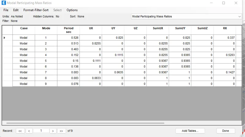
Modal participating mass ratio for the building model A:
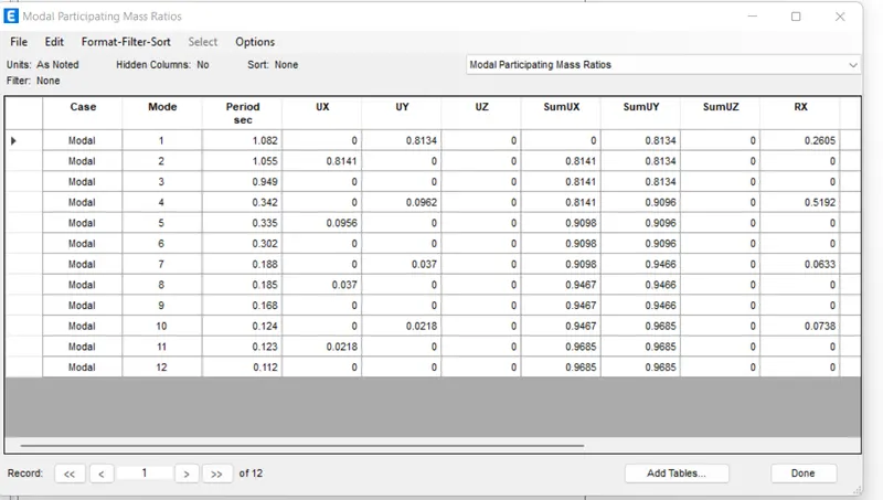
Modal participating mass ratio for the building model B:
Modal participating mass ratio for the building model F:
Modal participating mass ratio for the building model H:
All the four building models A,B,F,H are of different number of storeys with the different height and different mass so the time period for the building with the low height is less and the time period for the building model with the more height is more. The height of the building is directly proportional time period.But the mass participation ratio is more for the building A when compared to the other building models.
- Effect of column orientation on Time period:
Modal participating mass ratio for the building model B:
Modal participating mass ratio for the building model c:
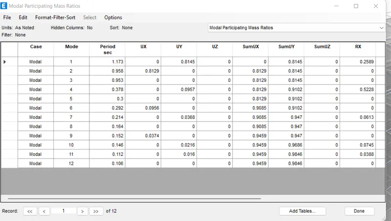
Modal participating mass ratio for the building model D:
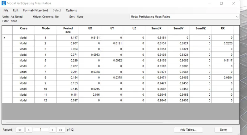
All the four building models B,C,D are of the three building units and the model B consists column unit 400x400 so the moment of inertia is same in both the axis. But the models C&D are same column units(300x550) but their orientation is different.So the moment of inertia regarding the longer direction axis is more and the stiffness is more based on the moment of inertia.The moment of inertia is more for the building model c so the natural period of the building model is more than the natural time period of the building model D. So the orientation of columns is also important consideration.
- Factors influencing mode shapes of oscillation:
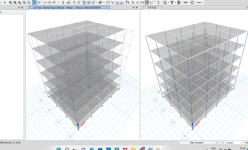
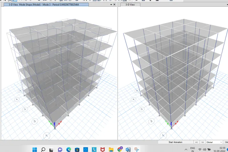
Mode shape of oscillation is the deformed shape of the building associated with the natural time period when the building is shken due to the earth quake forces.so for a building has many nodes. For a building there are infinite number of natural periods but the building is generally discretized into number of elements. The junction of these elements are called as nodes and each node is free to translate in all the three cartesian directions and rotate about the three axes and if the number of nodes is N then there will be 6N nodes of oscillation.
- Effect of flexural stiffness of structural element on mode shapes:The flexural stiffness of beams relative to that the adjacent columns depends on the thickness of the beams the deformation shape is not unique in all the cases.
Deformation shape is in direction of X when the mode of oscillation is in X axis direction and the mode of oscillation shape is about to rotate along the Z axis.
Basically it it is checked for the two or three modes to analyze the defoormation shape of the building unit.
- Effect of axial stiffness of vertical members on mode shapes
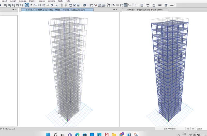
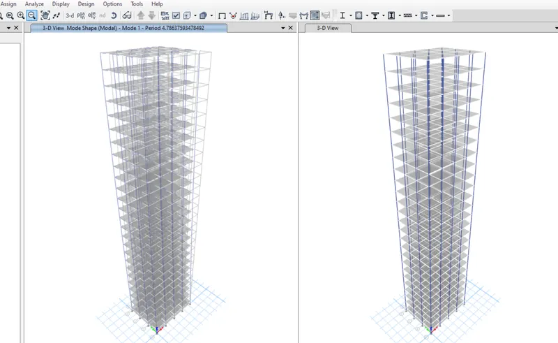
Based on the axial stiffness the mode shape may vary when the axial cross section is more then there will be shear deflection and when the axial cross section is less then there will be flexural deflection.
- Effect of degree of fixity on column bases on mode shapes:
The column bases may be either fixed or pinned based on their end codition the deformation shape is varied i.e the deflection may change. The pinned connectionn may have more deflection as it allows more moment where as the fixed connection may have less deflection as it firmly fixed to the end support and it does not allow any momnet in the structure.