Project 1_Comparative study of different storey buildings for Seismic forces
Factors influencing the Natural Period of a building.
Aim: To identify the factors influencing the antural period of building.
Introduction:
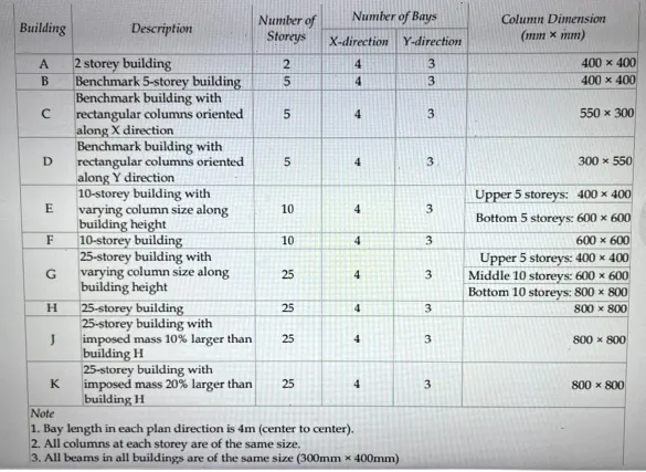
Buildings considerate to illustrate concept of natural period: details of 10 Buildings considered.
Model investigations:
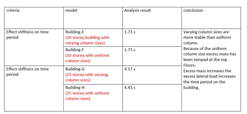
- Effect of stiffness on T: Compare fundamental natural periods of buildings E & F as
well as G & H. Why is there a marginal or significant difference in the fundamental
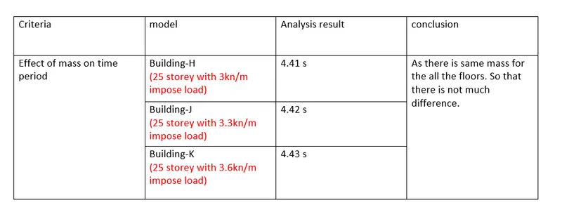
natural periods? - Effect of mass on T: Compare fundamental natural periods of buildings H, J and K.
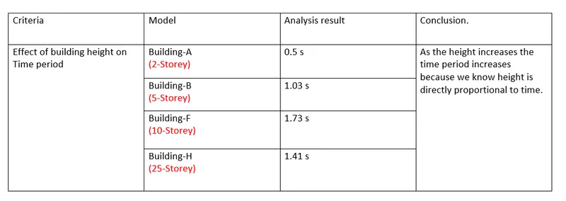
Have the buildings become more flexible or stiff due to change in mass? - Effect of Building Height on T: How does the fundamental natural periods of
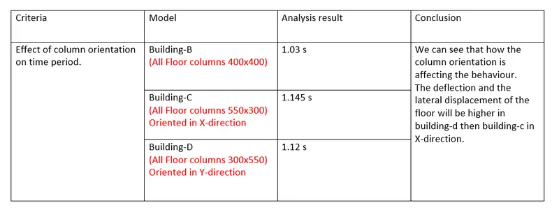
Buildings A, B, F and H change with change in building height? - Effect of Column Orientation on T: How does the fundamental natural periods ofBuildings B, C and D change with change in column orientation?
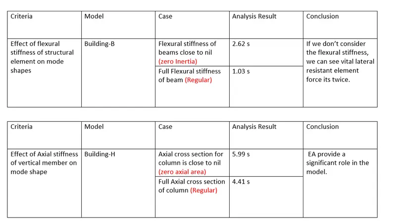
- Effect of Flexural Stiffness of Structural Elements on mode shapes: Compare
fundamental mode shape of Building B in two situations when flexural stiffness of
beams relative to that of adjoining columns is very small versus when it is large. - Effect of Axial Stiffness of Vertical Members on mode shapes: Compare fundamental mode shape of Building H in two situations when axial cross-sectional area of columns is very small versus when it is large.
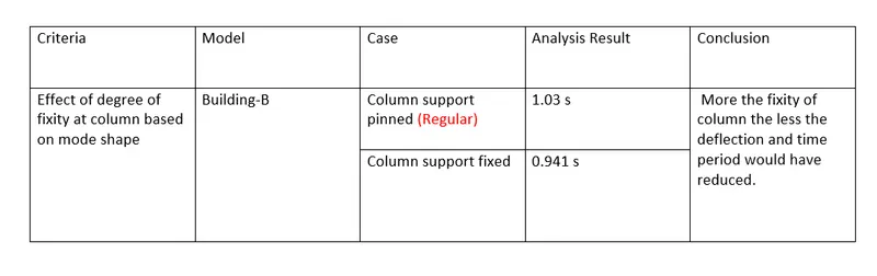
- Effect of Degree of Fixity at column bases on mode shape: Compare fundamental mode shape of Building B in two situations when base of columns is pinned versus when it is fixed.
Procedure:
As per the table we will create all 10 sample model in the etabs.
Model a:
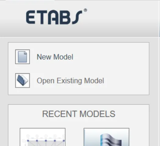
First we need to open the ETABS software and then click on the New Model to create new project.
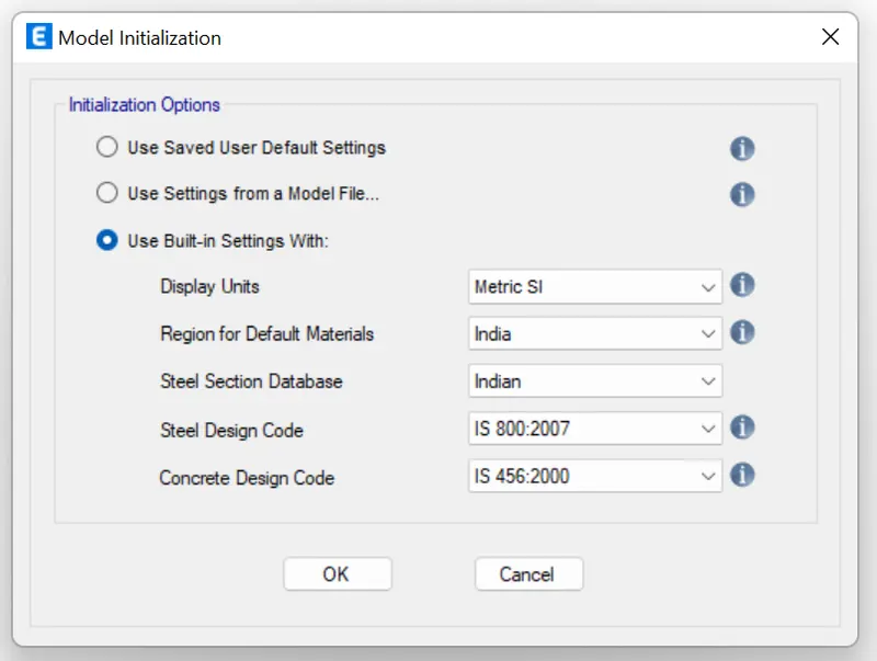
Now use the built in settings. In the model information.
Now provide the model grid information.
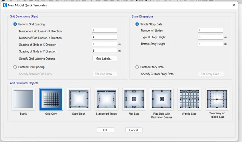
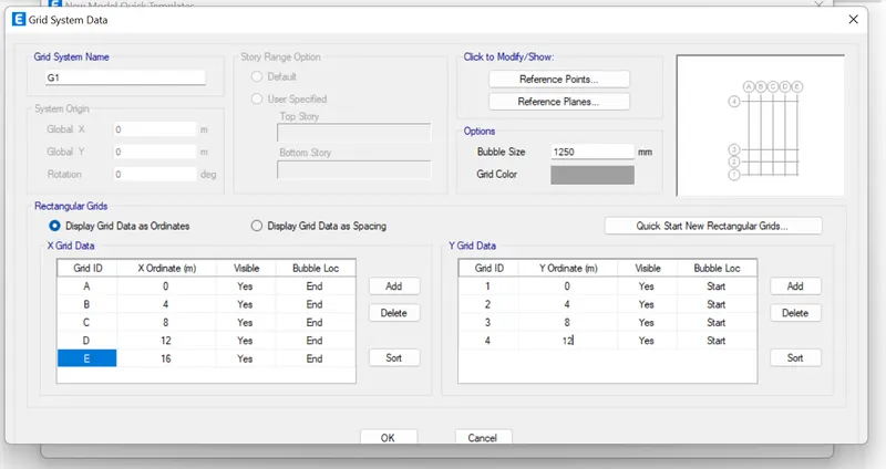
by using customise Gride spacing.
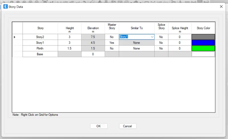
Now click on of and give the story Data
As in the model a we just have the two story wenned to provide the story data in the model.
Once we click on OK we can see the model has been generated in the screen.
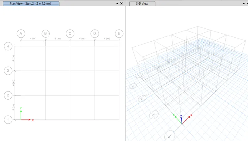
Now we need to give add the material data in the model.
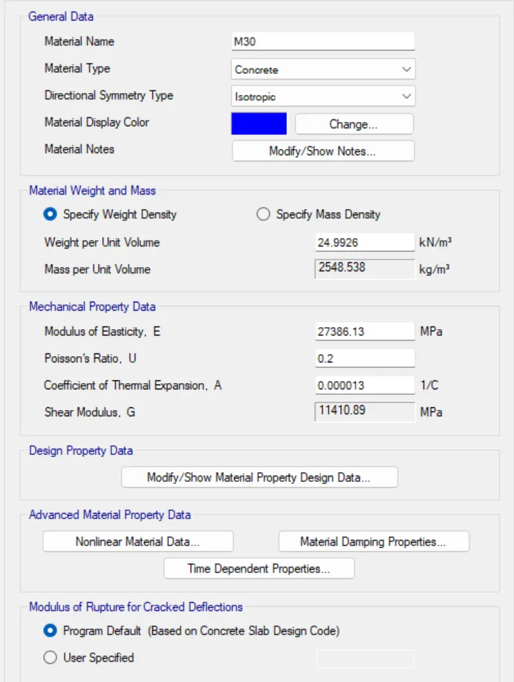
Click on define in the ribbon tab and go to material properties and then click on the add new material.
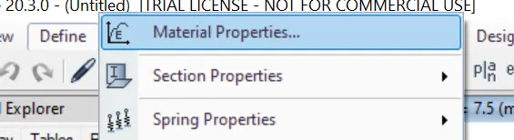
Add the material becouse we dont have any concrete are rear according to the Indian Standerds.
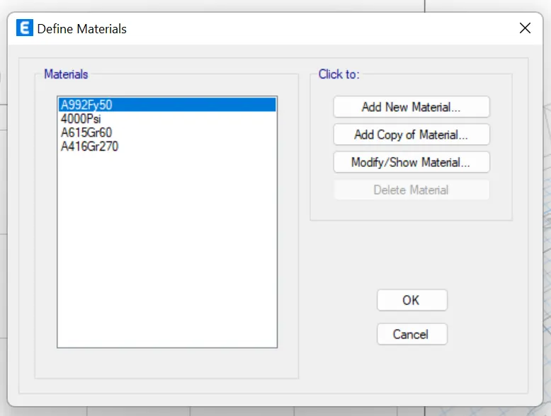
add the materials now
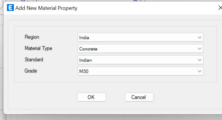
Oncrete
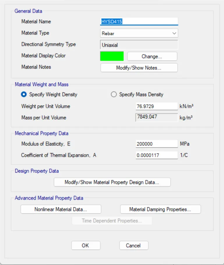
NOw add the reinforcement material.
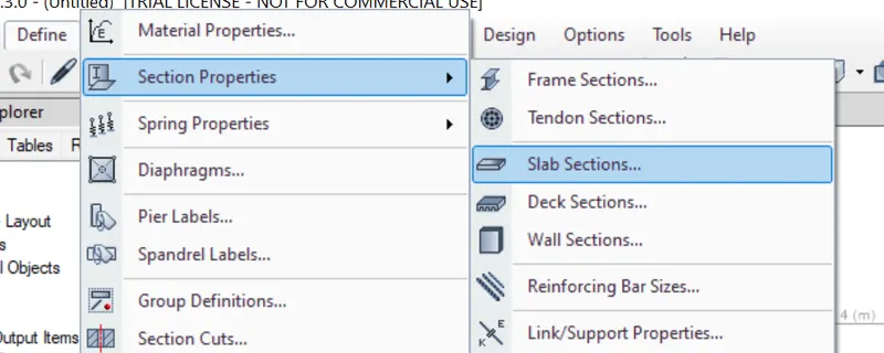
To add the slab material properties click on the define and click on the section properties and then click on the slab section.
now click on the add properties.
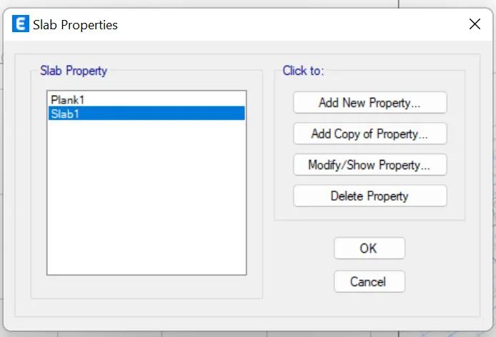
click on the add new properties. now give the properties of the material.
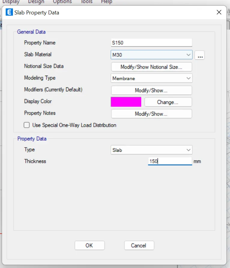
now defining the sectional properties for frame.
Click on the define in the ribbon tab and click on the sectional properties and the frame section.
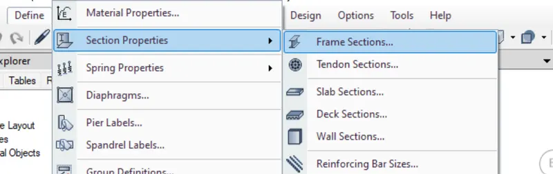
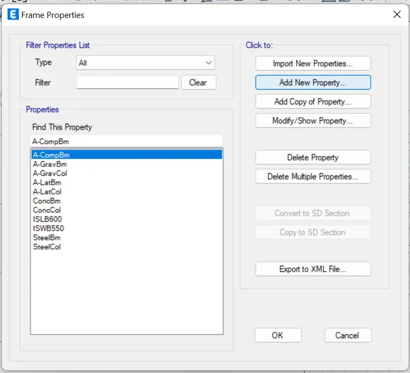
Now we can see new tab select the add new properties of beam section.
Material dimension and the properties.
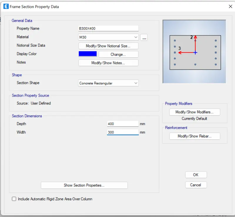
now click on the modify reinforcement.
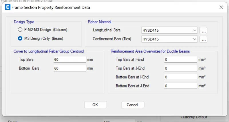
once it is done click on ok beam materials will be added .
To define column properties click on the add materials again and select the frame shape.
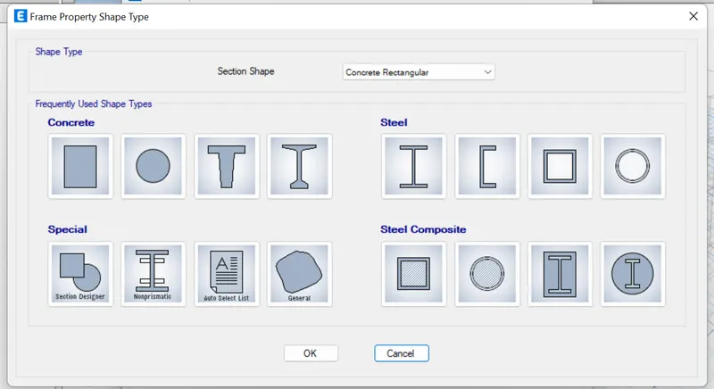
now give the material properties.
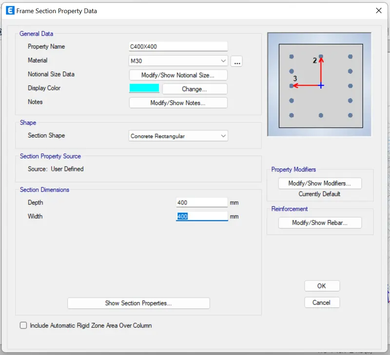
Click on the edit reinforcement.
And give the material rebar properties.
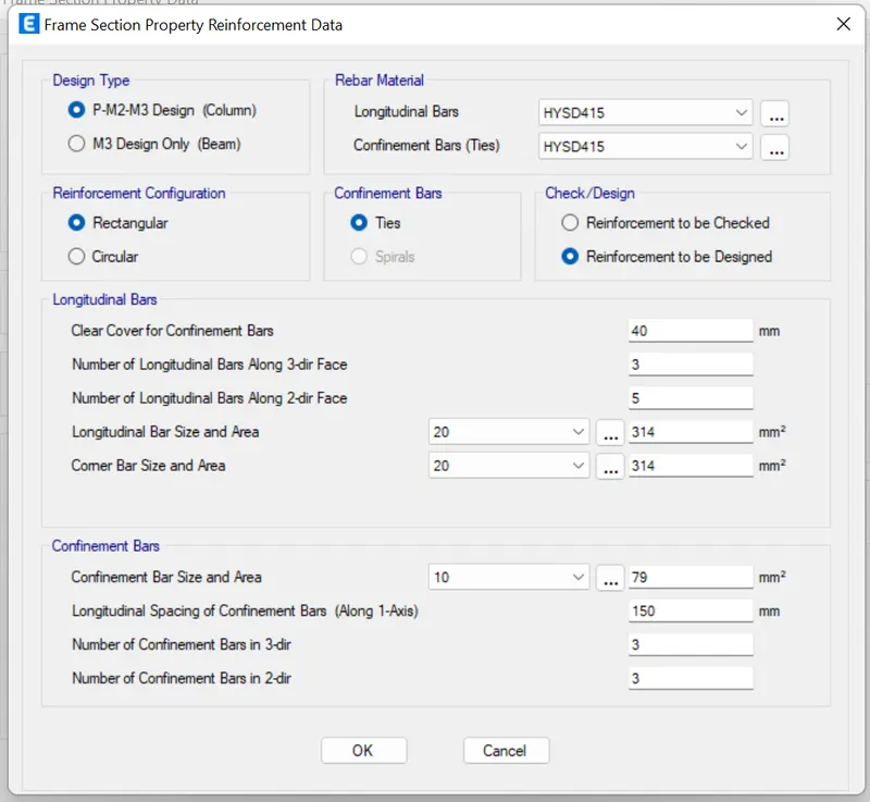
Then clik on OK to add the material to the frame propeties.
Now define the load patterns. click on the define inthe ribbon and click on the load patterns.
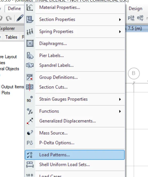
now add the load patterns and then edit the
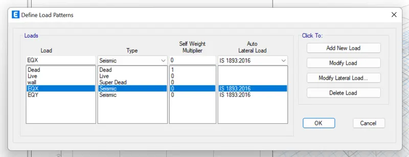
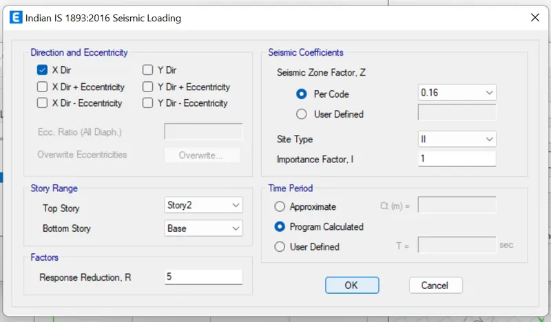
Modify lateral loades with respect to the EQX
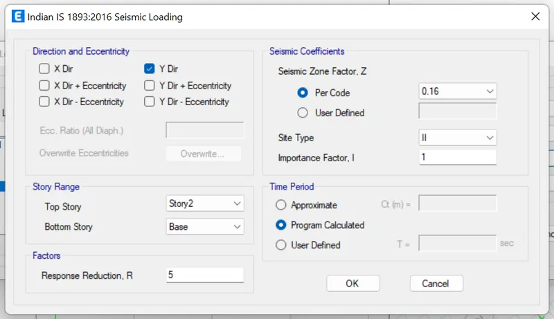
Now EQY
Now to add the mass source click on the define and add the mass source.
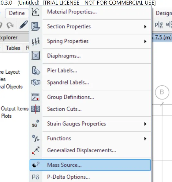
Now click on the add mass source.
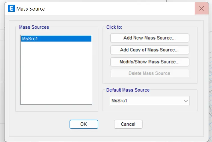
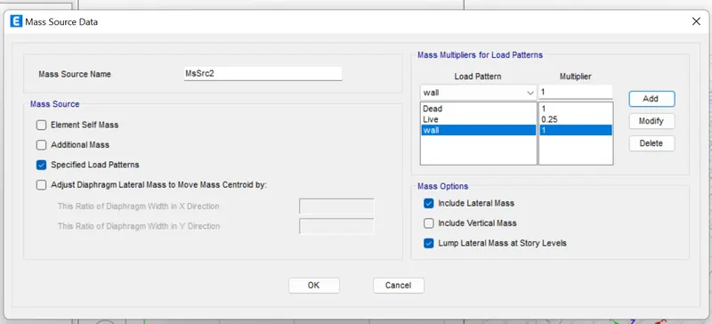
give the load patterns for the loads according to the standerds.
now to create a load combinations click on the define in ribbon bar and click on the load combinations in the bar.
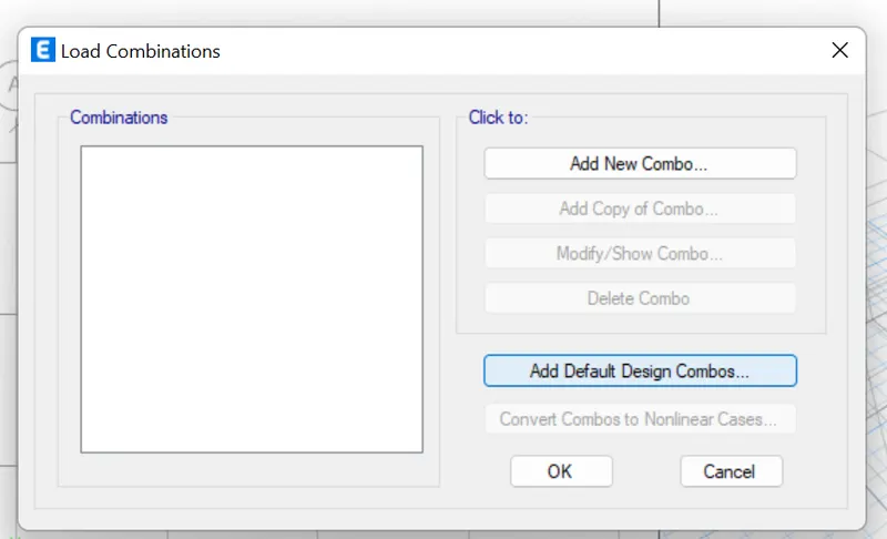
Now click on add default design combo.
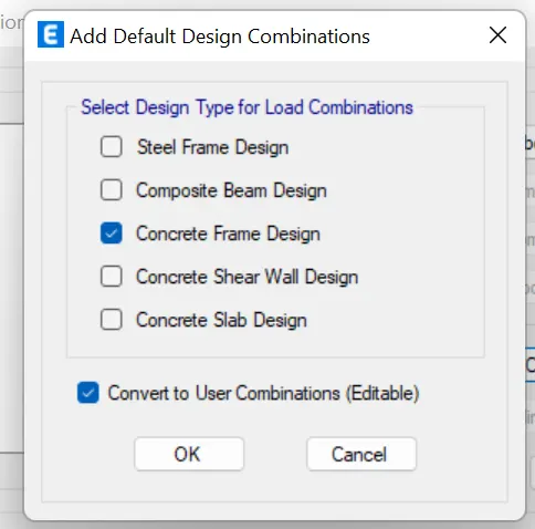
now click on Ok.
now to draw a column click on the quick draw columns in the left bar.
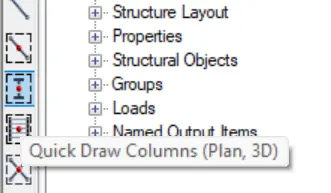
now select properties of the object. in the left side of the screen.
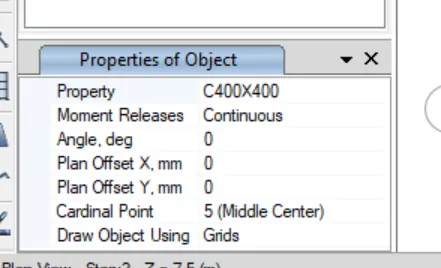
now select the all the storeies in the right down on the screen.
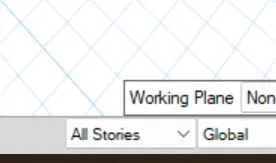
now click on the intersection of the grids and place the columns.
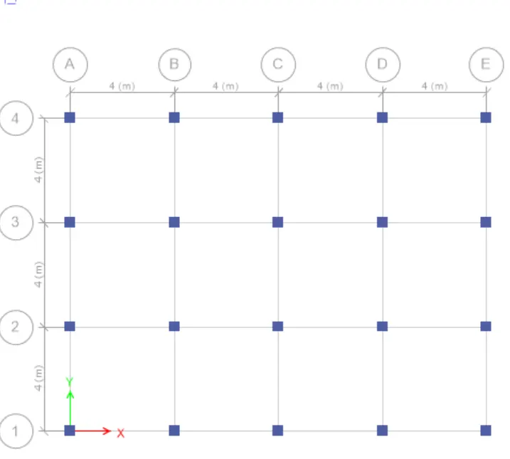
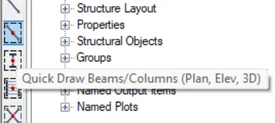
now use the quick draw beam icon on the left of the screen.
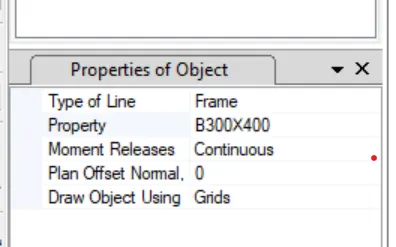
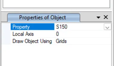
now change the properties in the left hand side and ensure all storyes oprion is selected.
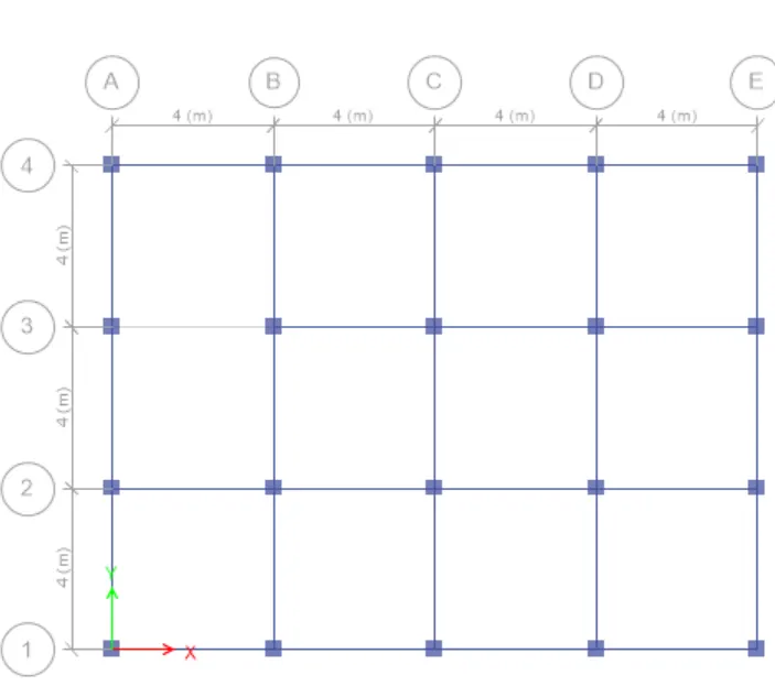
now select the line and place the beams.
now use the quick draw slabs and draw the inthe left hand of the screen.
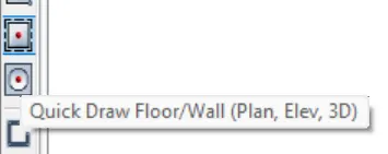
now select the properties in the left side of then screen. then choose the simillar storys.
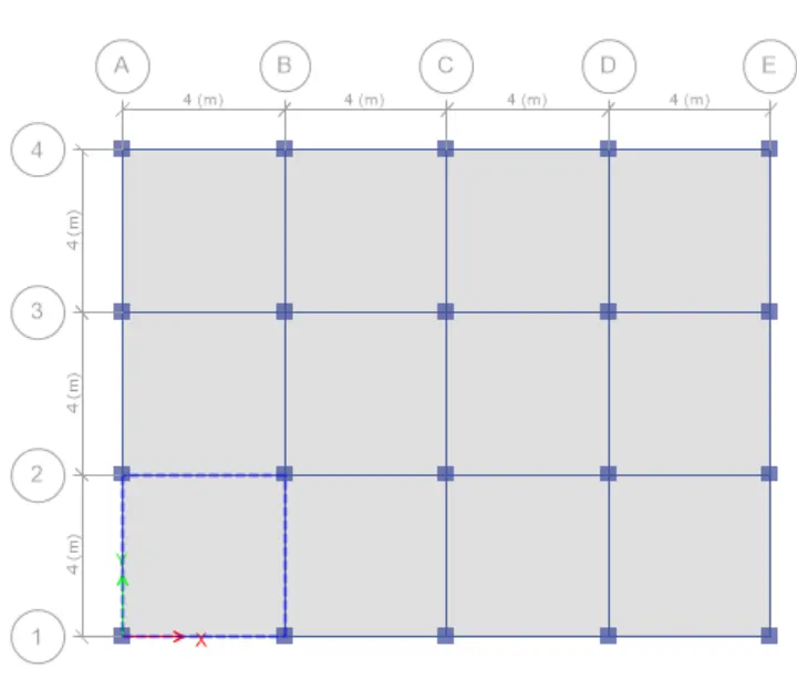
now seelect the floor in between the boundreis and floor will be created automatically.
To Assain the loads we need to select the beams first.
Click on select options.
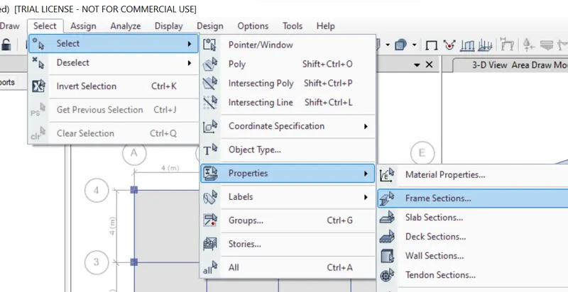
now we can see all the beams has been selected.
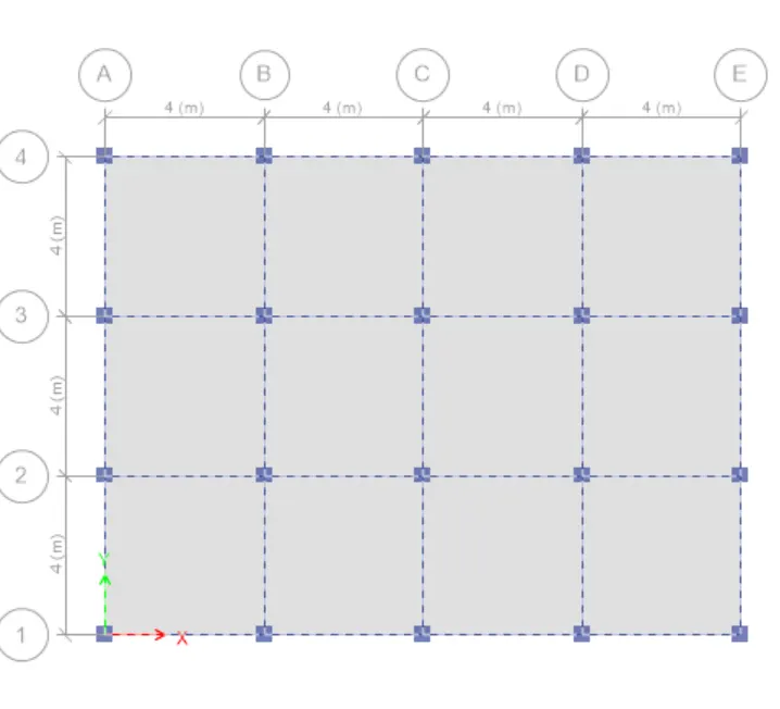
Now click on the assaign to assaign loads.
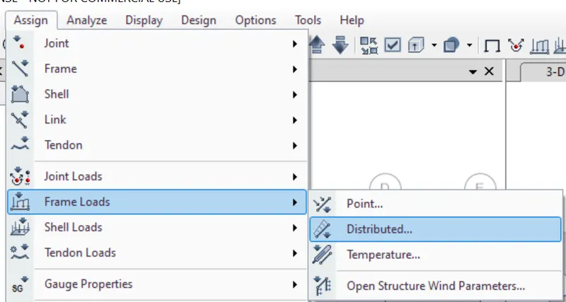
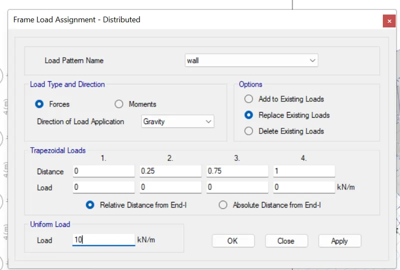
now select the wall and give the load then click on apply and ok.
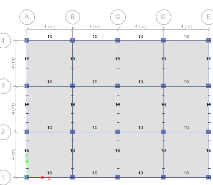
we can see load have been assaigned.
Now select the slab properties in by using the select option in the ribbon bar.
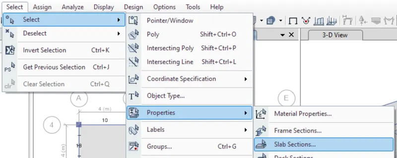
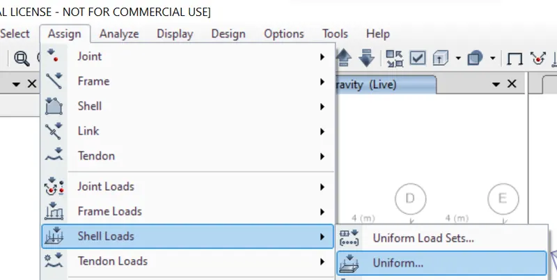
now click on assaign and click on the shell and click on the uniform load.
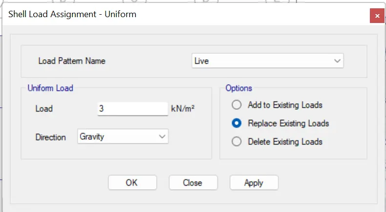
now give the loads and click ok.
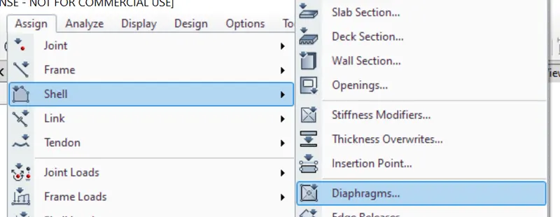
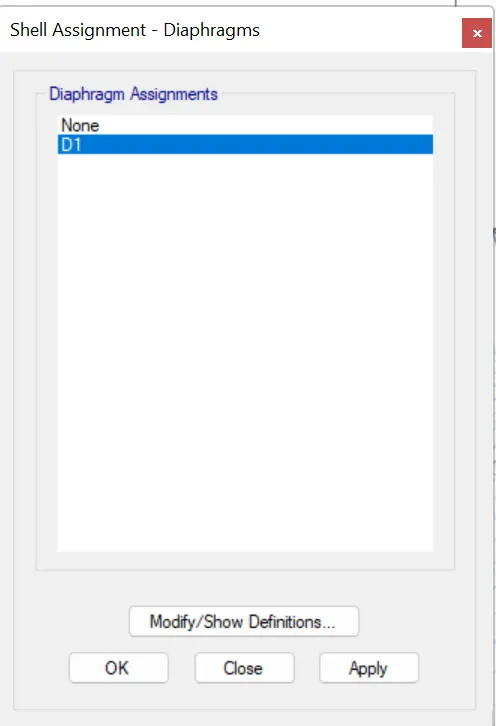
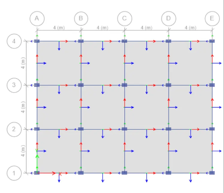
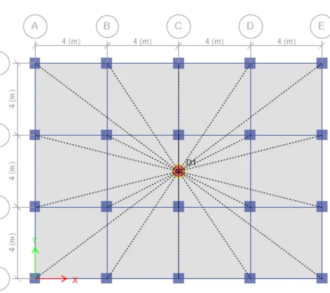
Now we need to provide diaphrame property we need to select all the slabs again.
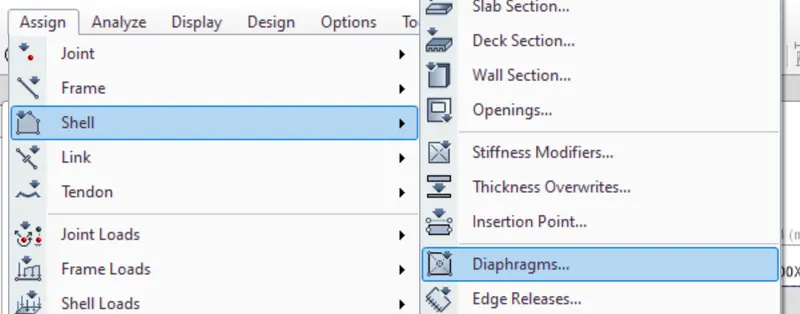
After selection of the floor click on the ad=ssaign and then click on the shell and the diaphragms.
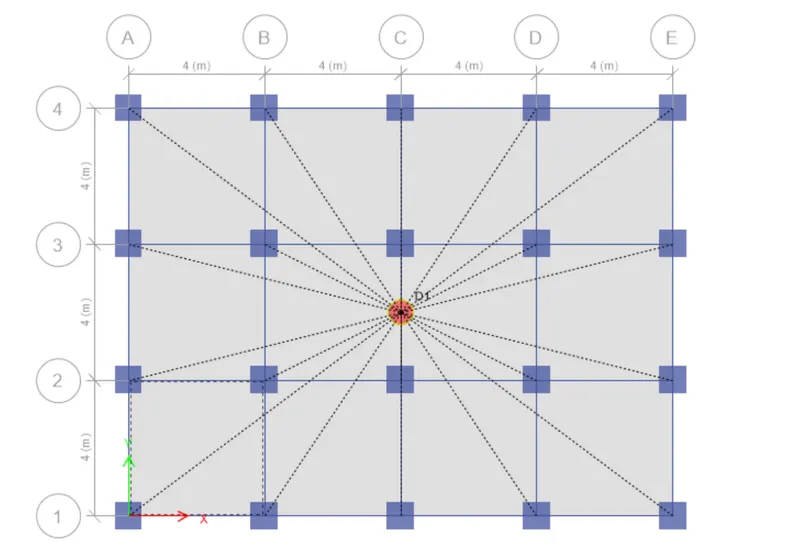
Then select tht D1 and click ok.
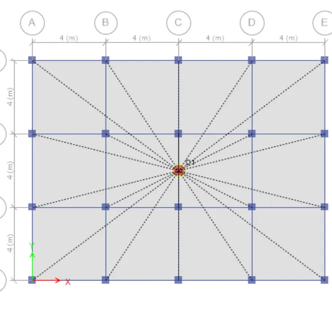
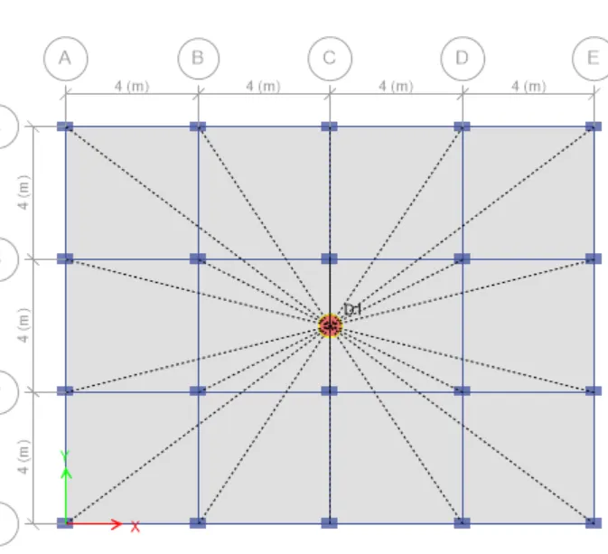
Now we can see that center of mass has been created for the plan.
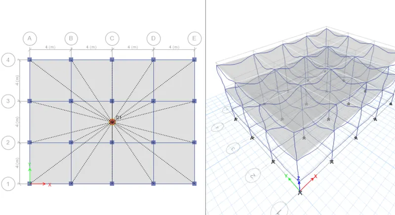
Now click on the run Anlysis on the ribbon bar. save the project as model a.
We can see the analysis of the building.
Model b:
Now for the model b we have five story buildin as per the table.
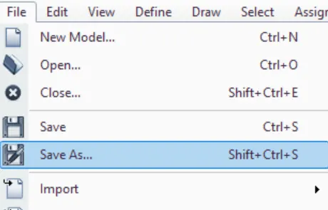
We can use same file save as the model name it as model b. So that we dont need to recreate every thing.
As all the colum sizes for the b is same we can go to Edit option in the ribbon tab.
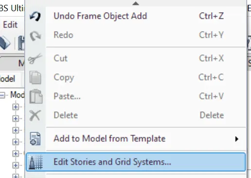
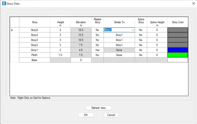
Now click on modify story data and click .
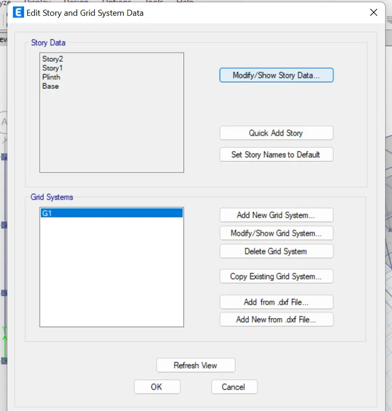
now click on the add story.
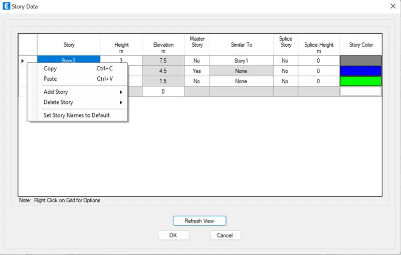
Then give the no of storys.
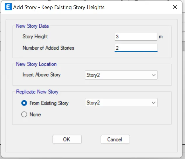
then click on ok. now we can see that story has been added to it.
Now check the floor loads are visable we nee to click on the shell loads icon in the ribbon bar.
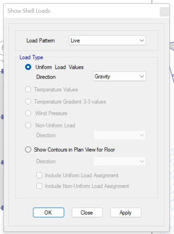
now select live in the tab click Apply and OK.
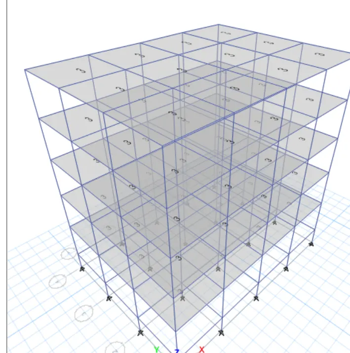
Now we can see the floor loads has been assaigned.
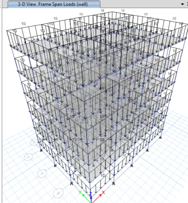
Simillarly check the wall dead load has been assaigned.
click on the frame load icon in the ribbon.
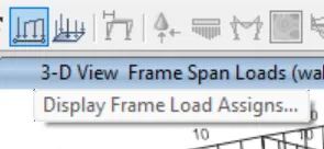
Select the wall type and click apply then we can see the loads which has been assaigned below.
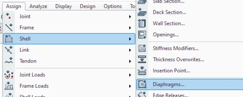
Now select the slab by using the select option in the ribbon bar.
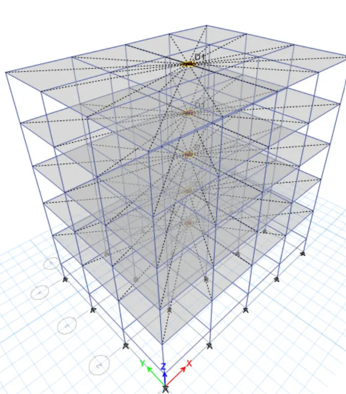
Now click on the assaign and select the diaphramges.
After we can see the center of mass has been created.
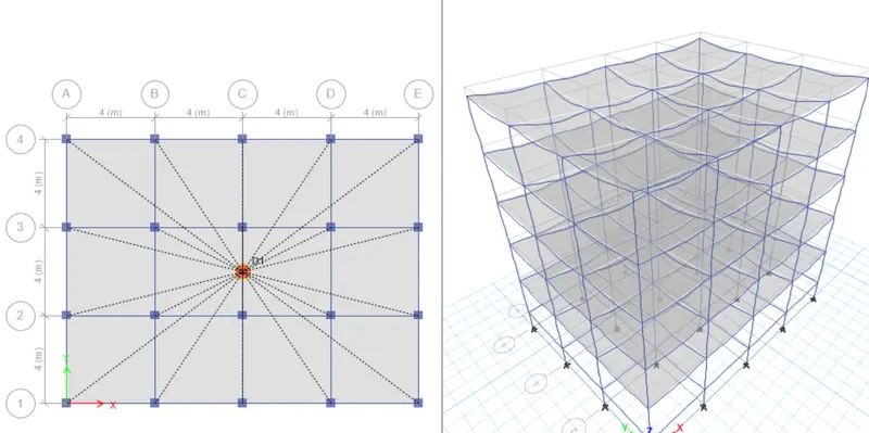
Now run the analysis by cliccking on run analysis option in the sribbon bar.
As a result deformed shape will be shown.
Model c:
Now click on the save as and save as model c.
As we can see in the model c is the same 5 story but with the different column size.
Now to change the column property click on the define in the ribbon tab then click on the sectional property then select frame.
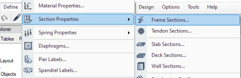
Now select column and click on the modify property.
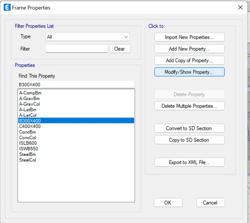
then change the property as per the table.
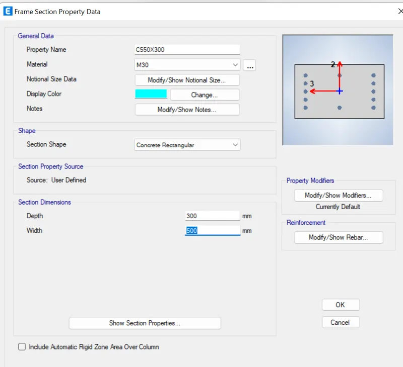
Check the rebar modifications and click on OK. you can see the column in the change.
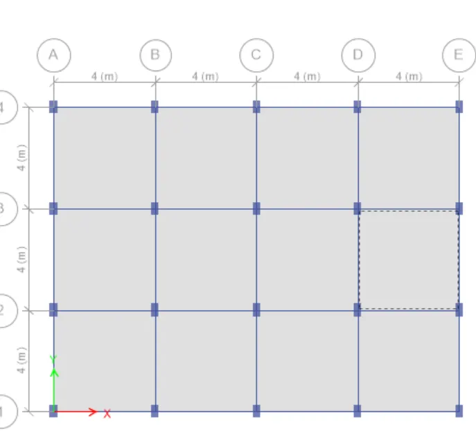
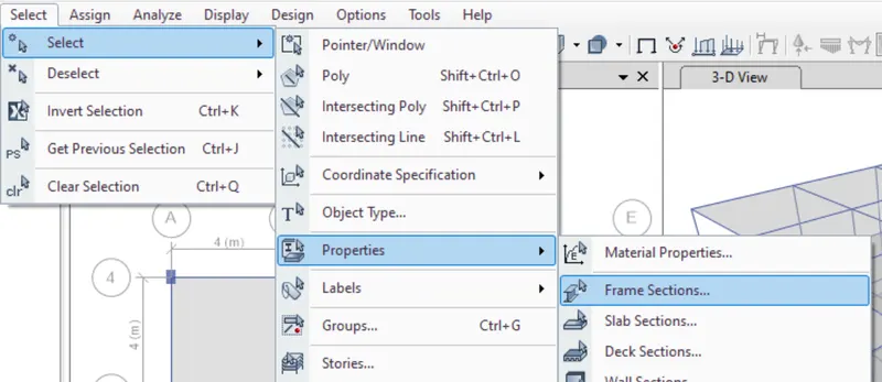
We nee to keep orientation of the column in the X-Direction click on the select in rebar and select all the column.
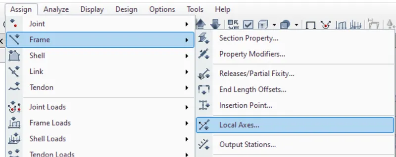
now click on the assaign then frame and the local axis.
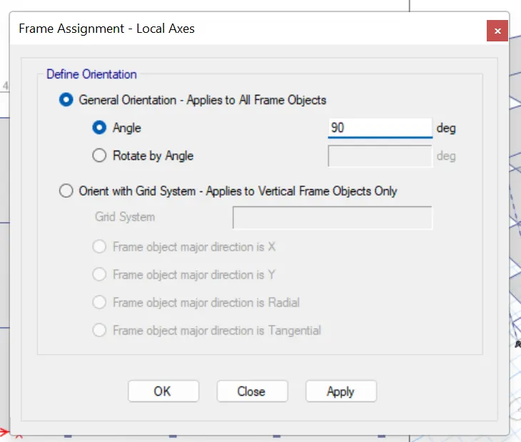
now provide angle and then click on Ok.
Now we can see the orientation of the columns has been changed.
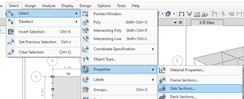
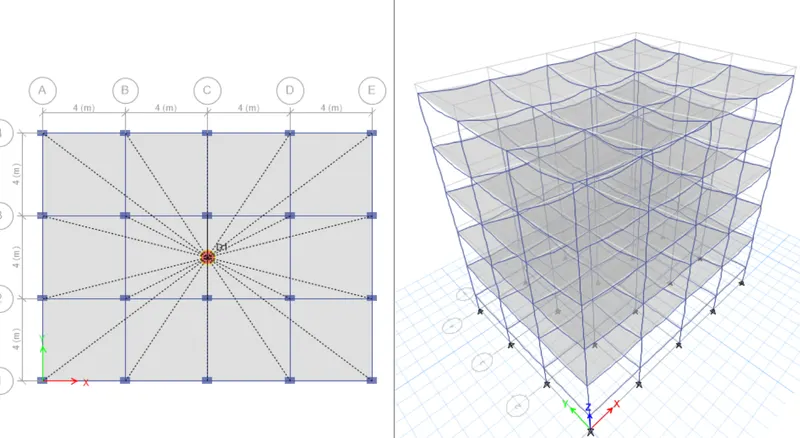
now select in the ribbon click properties select slab.
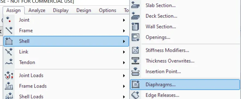
now click on assaign then select the shell and the diaphagrames.
Now we can see the center of mass.
now click on run analysis on the ribbon bar.
Then we can see the deflection shape.
Model d:
Now click on the file then save as model d.
As per the table in the model d orentation of the model is in the Y-Direction this is the only change in the model.
now click on the select then click on the properties the click on the frame.
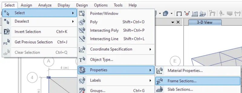
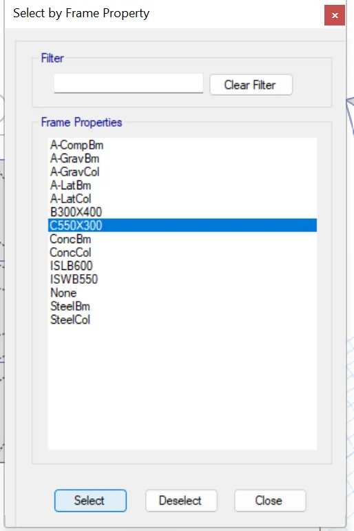
Now click on the column and the click on the ok.
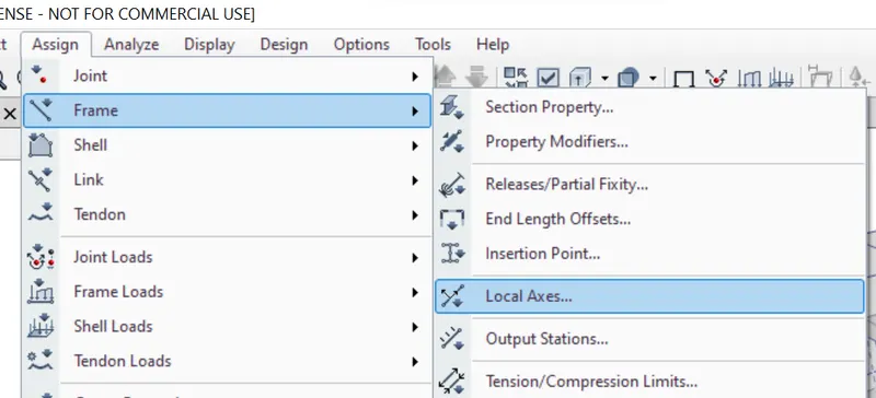
Now click on assaign the click on the frame then click on the local axis.
Now change the anle then click on.
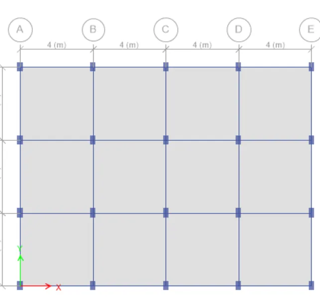
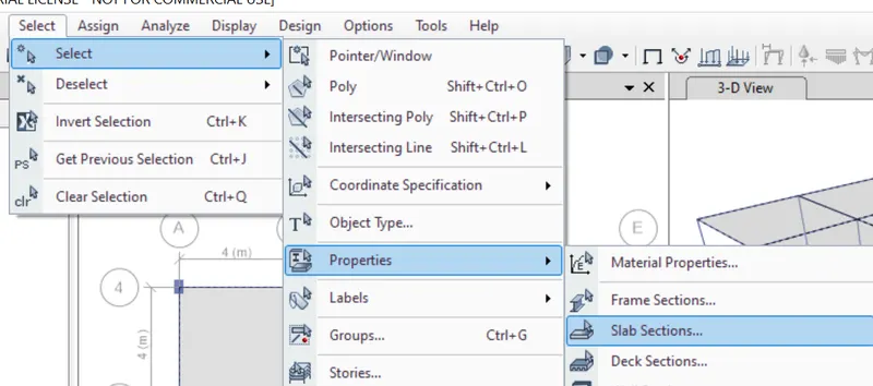
Now click on the select in the ribbon and then select the slab property to assaign diaphgrames.
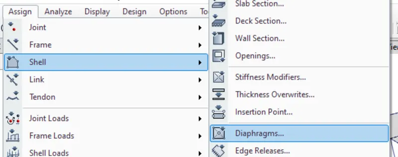
Now click on the assaign in the ribbon tab then click on the shell and then diaphagrames.
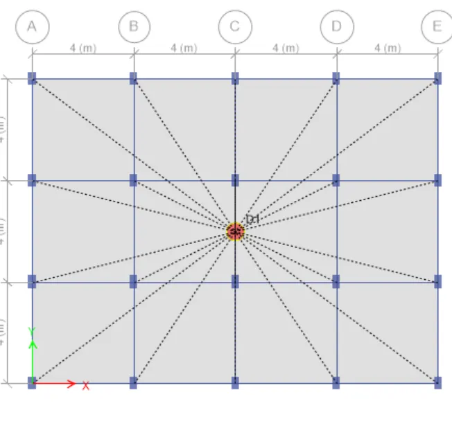
Now we can see the center of mass .
Now click on the run analysis in the ribbon bar.
We can see the deflection after the analysis.
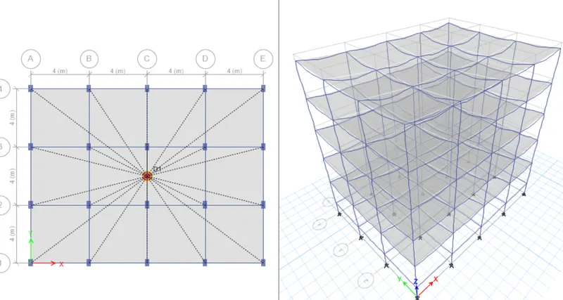
Model e:
Now click on the file then save as the model e.
For the model e there is 10 story building and the different column sizes.
First we will add the floors. Click on the Edit then click on the edit story.
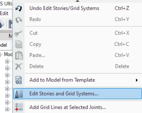
Now click on the modify story data.
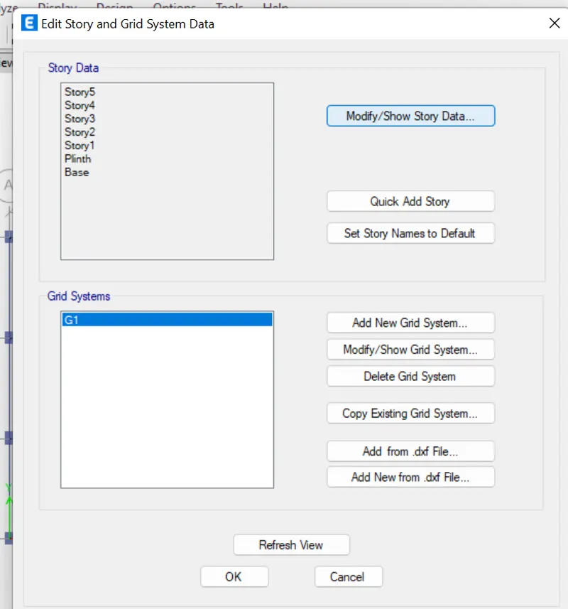
now click on add story.
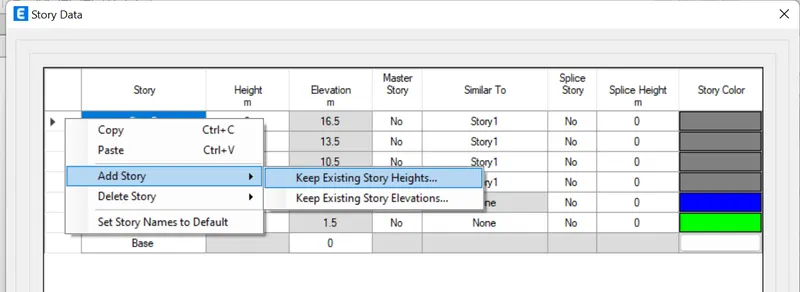
we can see the story has been added to the model.
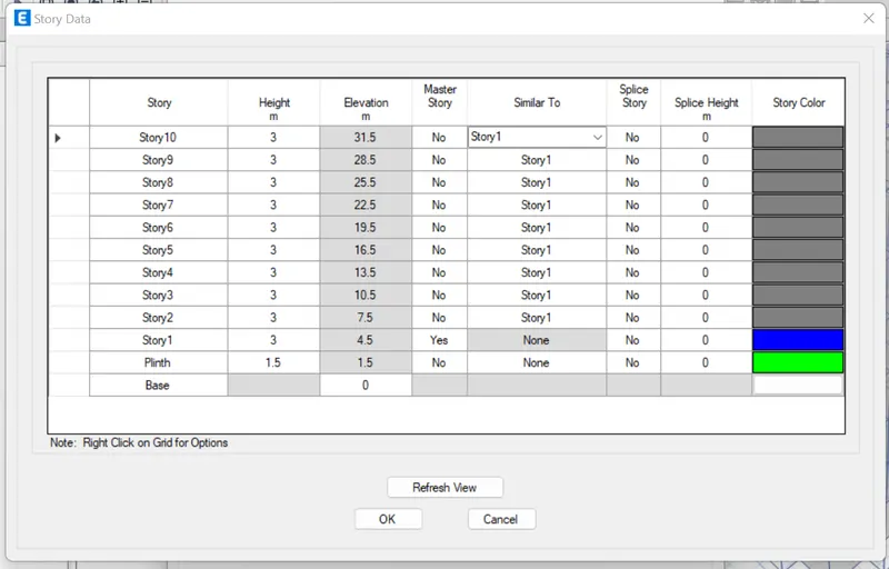
Now check the floor loads and the column has been added to the model.
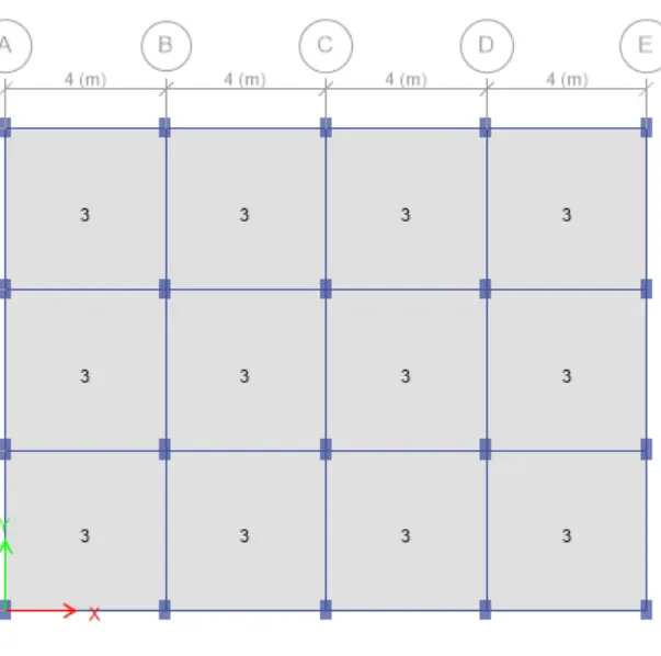
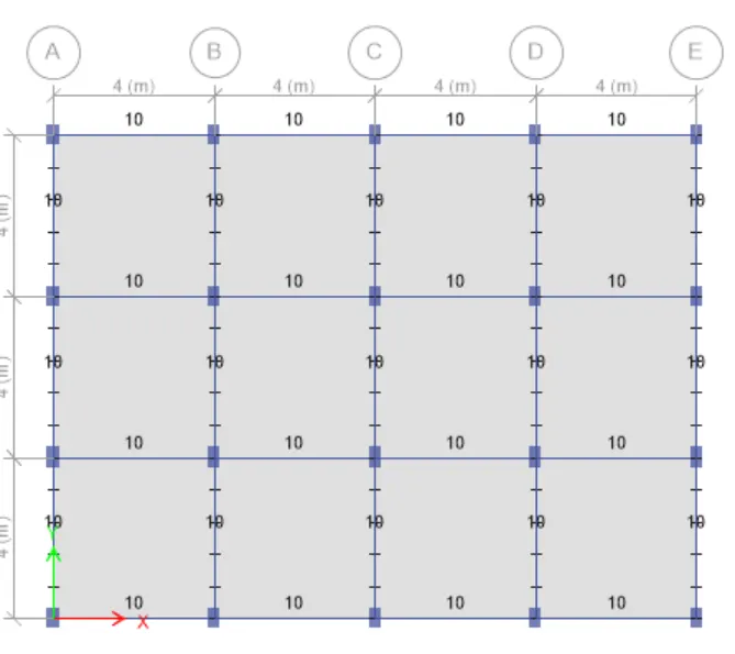
now to change the column column dimension we need to select the column.
now click on the ribbon bar the click on the define then click on the section an then frame.
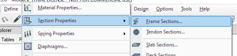
Now select the column and the click on the modify.
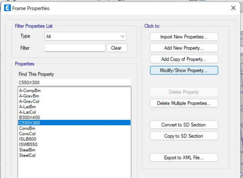
Now give the dimension of the column and then click on ok.
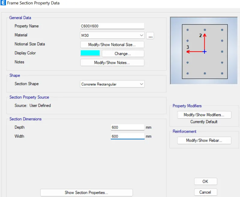
Now add the new column. Add the properties.
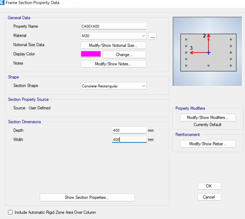
Now click on the modify rebar with the specific codes.
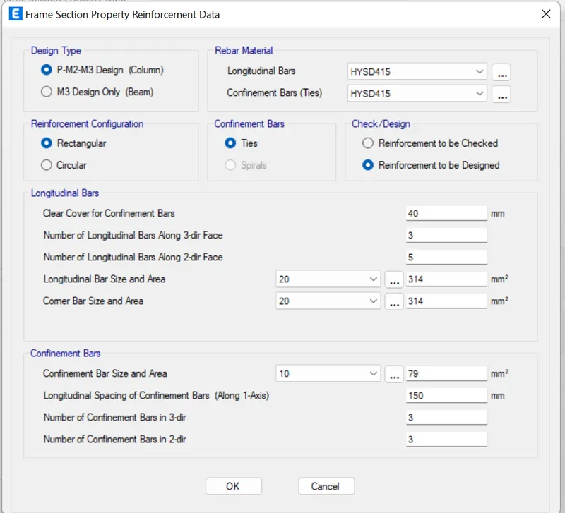
Now we can see the change in the colums.
Now we need to click on the set display options.
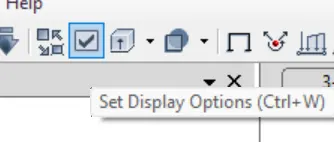
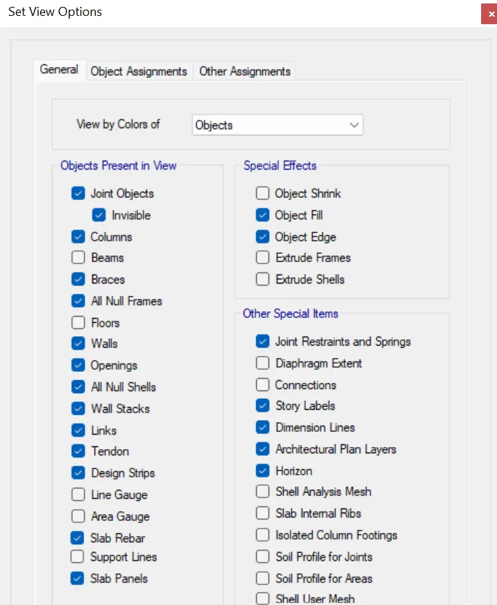
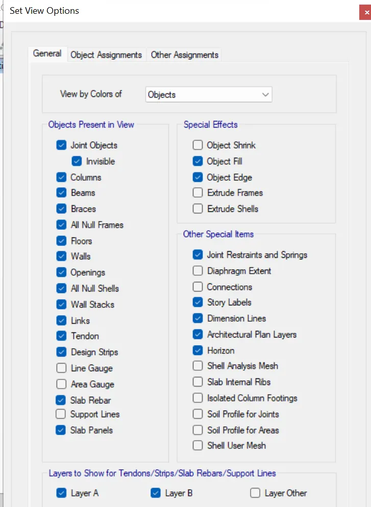
Now unselect the beams and floors.
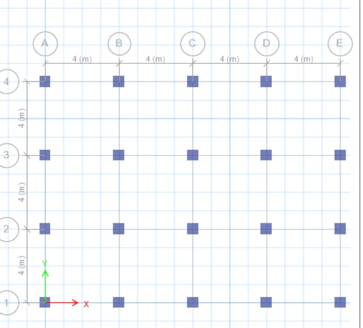
As a result we can see only columns.
now to select only from story 10-6 click on the view in the ribbon tab
Then click on the set up built limits.
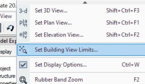
Now in the story range set the bottom and the top.
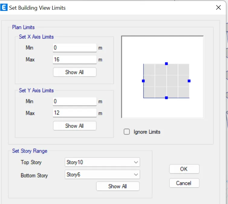
we cans see only top 5storys.
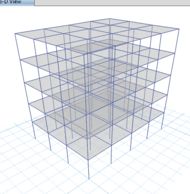
Now select all the columns by using the select option in the ribbon bar.
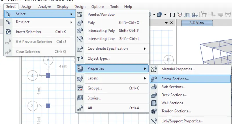
now click on assaign in the ribbon bar then click on the section properties.
now give C400X400 to them.
The click apply then click on ok.
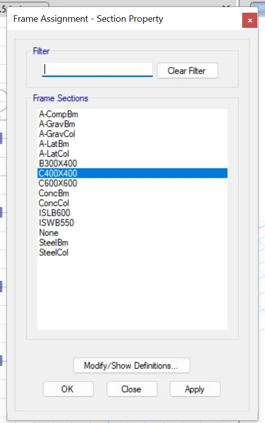
As a result we can seee the columns has been changed.
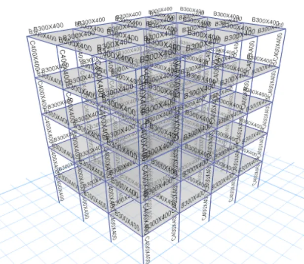
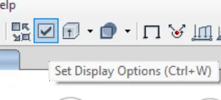
now we make beam and floors back click on the tick marck icon and select back beams and floors and click ok.
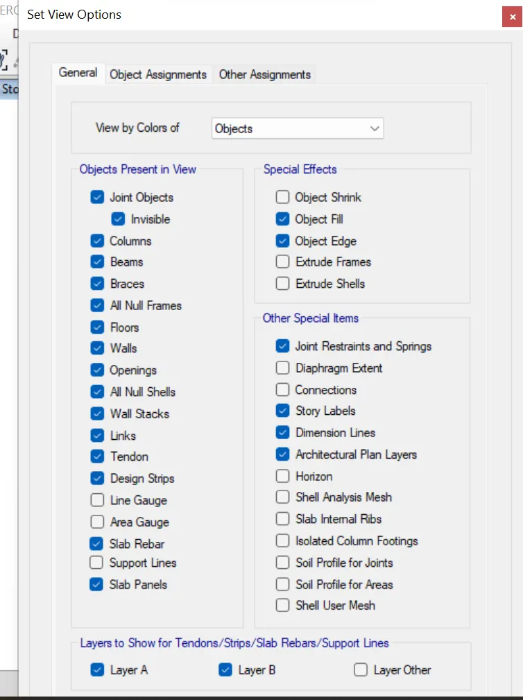
Now we can see the floors and the beams back in the plan.
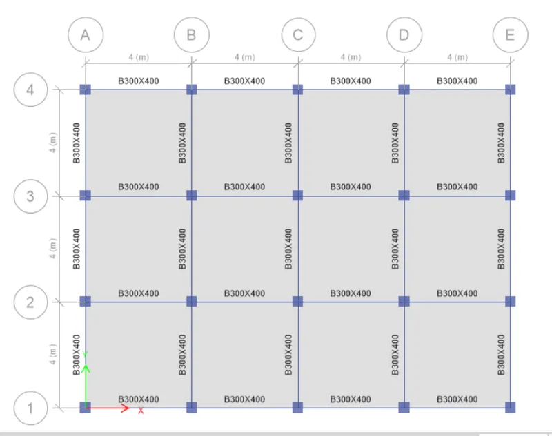
Now select the slab by usiging the select option in the ribbon tab. choose the properties and then choose the slab properties.
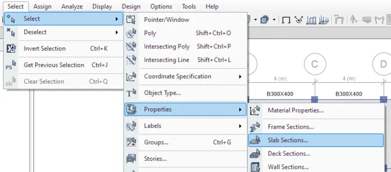
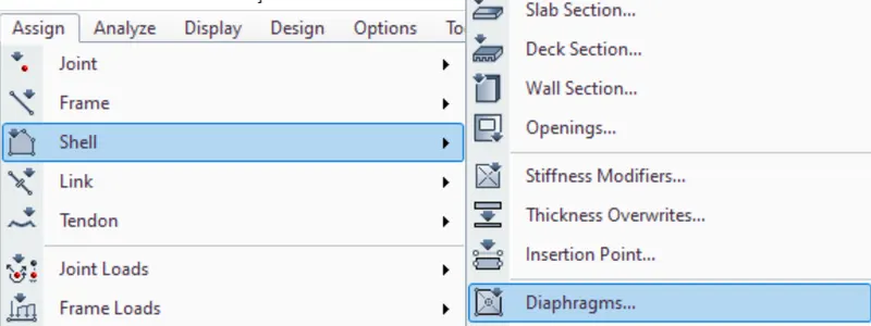
Now click on assaign then click on shell then chick on the diaphragmes.
now click on the run analysis.
we can see the analysis hs been done.
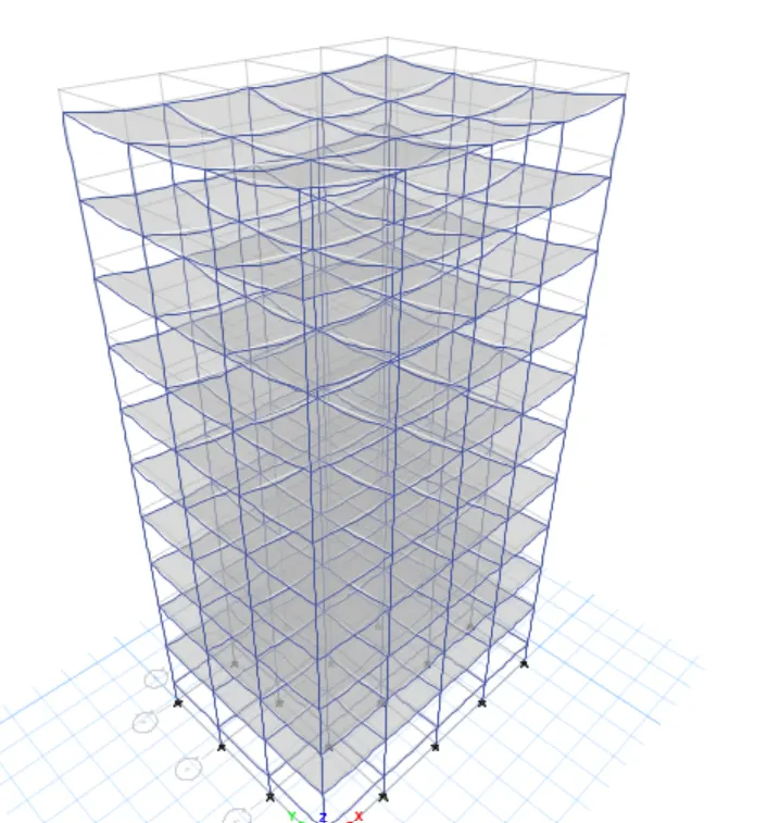
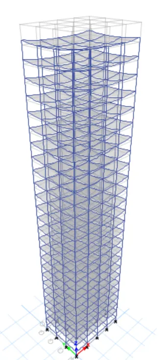
now we can see the deformed shape of the building.
Model F:
Now we save model as the save as model f.
The change in the model F is column size and everything is same.
Now to change the column sizes we need to we need to hide beams and floors.
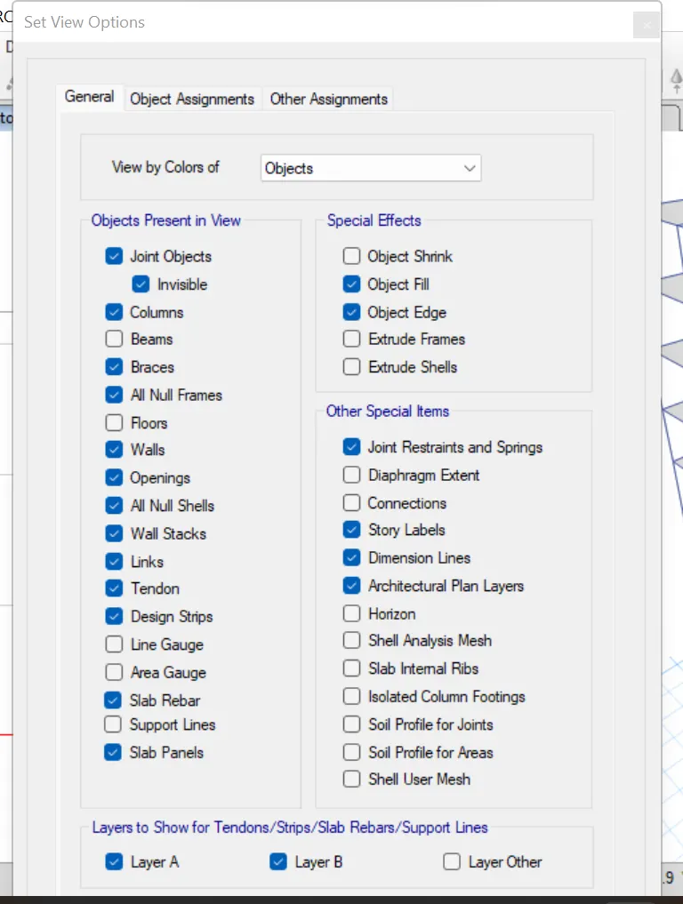
now we change the view limit of the building by using the edit option.
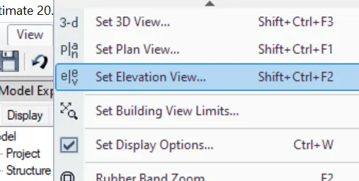
now click on the assaign then click frame and section properties.
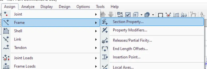
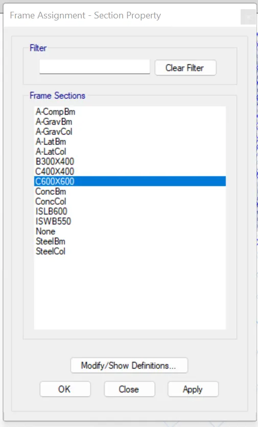
now select the properties of the column to change then click on ok.
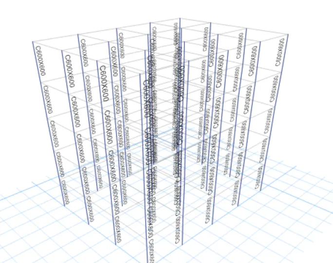
now we can see the changed properties.
now get back the floor and the beams in the section by usign the check tab.
now to assaign the diaphagrame click on the select option first then click on the properties and then click on the slab propperties.
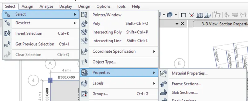
Now click on assaign then click on the shell and then click on the diaphrame.
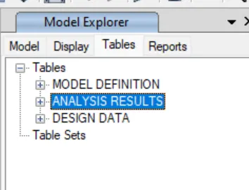
Now we can click on analyise. now we can see the anaysis.
Model G:
Now we need to save the model as model g by clicking the save as.
In this model the floors are different and the column sizes are different.
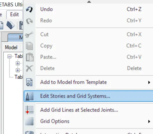
Now to add the story click on edit and then click on the edit story.
 '
'
NOw click on modify story data.
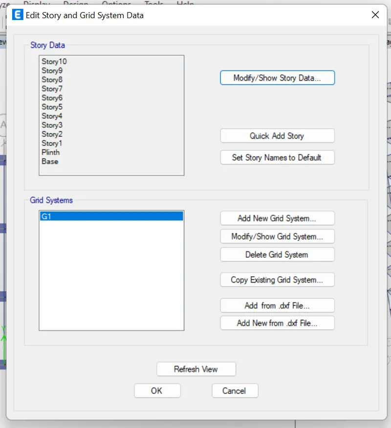
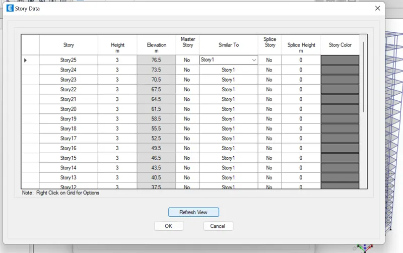
Now click on the add the story and give no of storys.
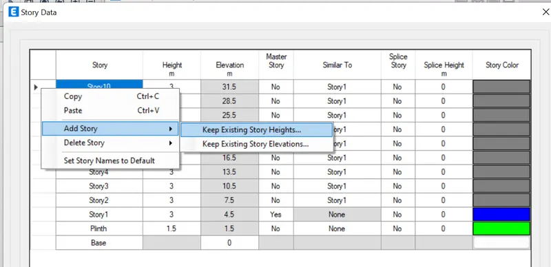
Now we can see the model has been added with the floors.
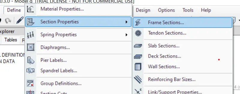
Now we have to define the column sizes. click on define then sectional properties and then frame.
now click on the add new property. now click on the add new propeties then select the rectangle
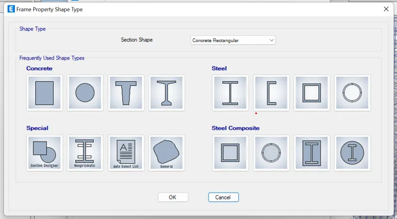
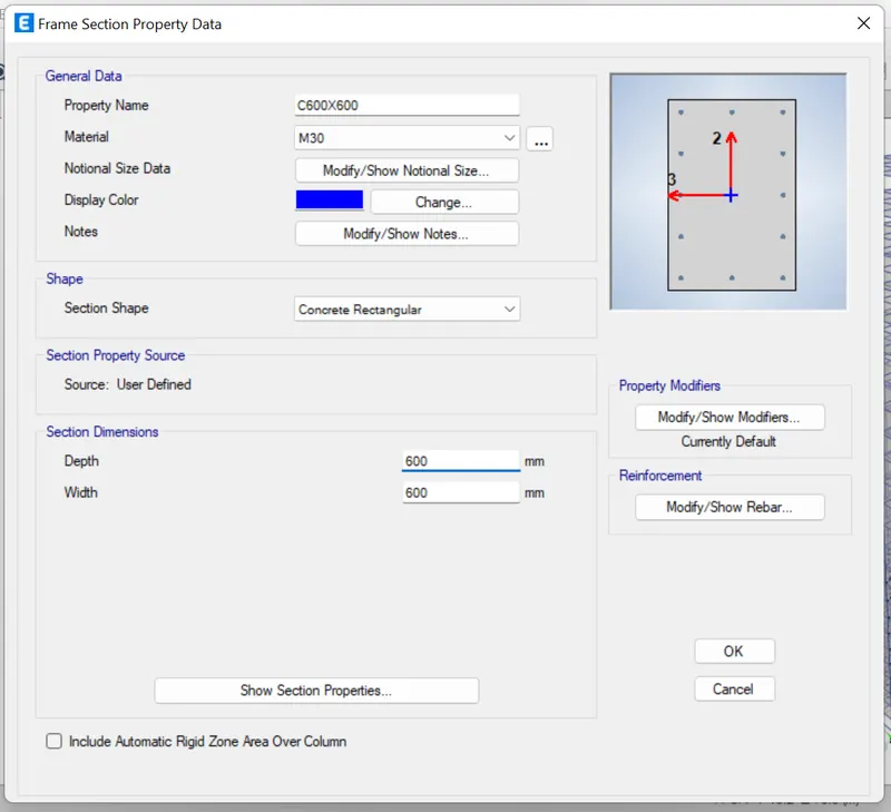
and give the properties.
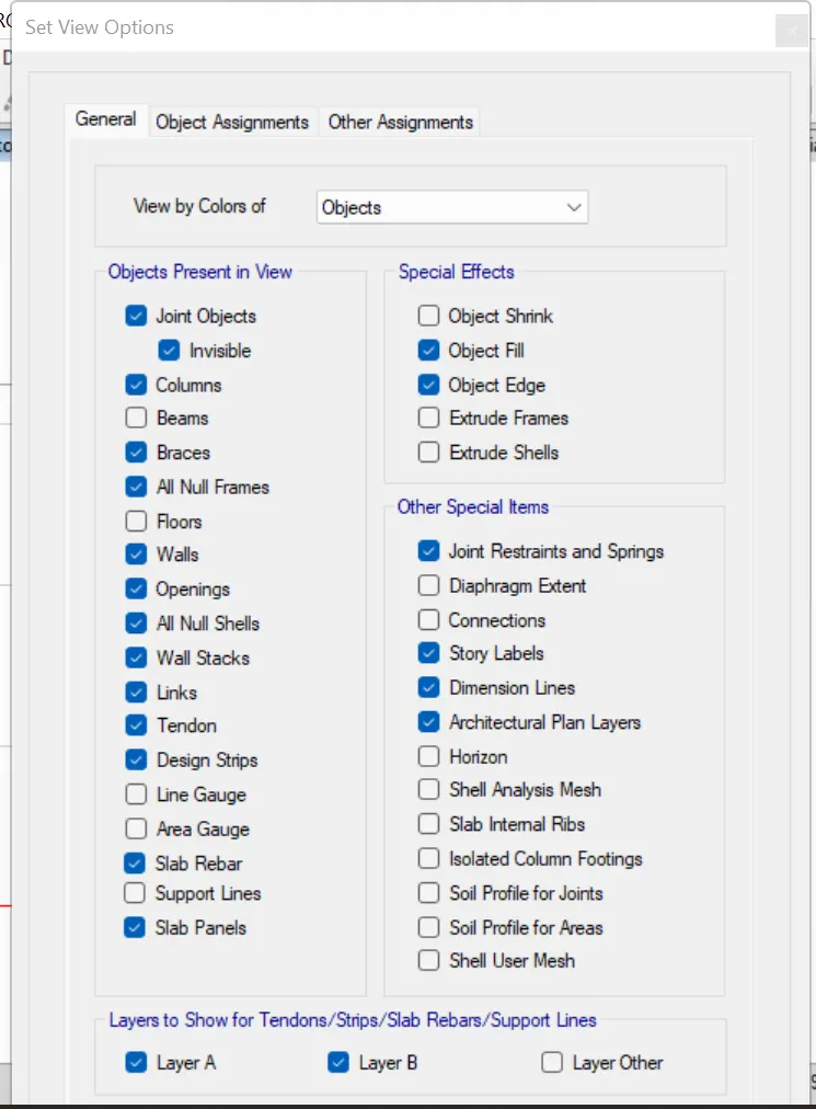
Now go to view option and hide the beams and floors.
Now as per the table we give column sizes to the floors sepertaly.
Now set the view limits of the building to 21-25m to change teh column sizes.
Now click on view and click on the building view limits.
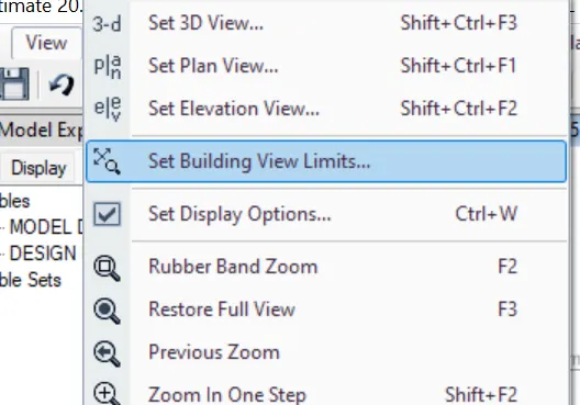
now select all the columns click on assaign then click on Frame then click on sectional properties.
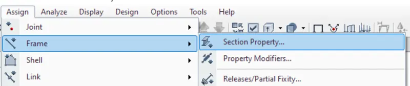
now we can see the chage in the section.
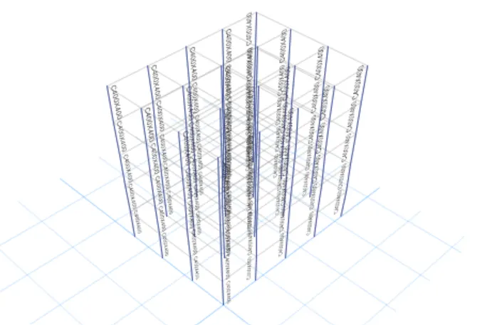
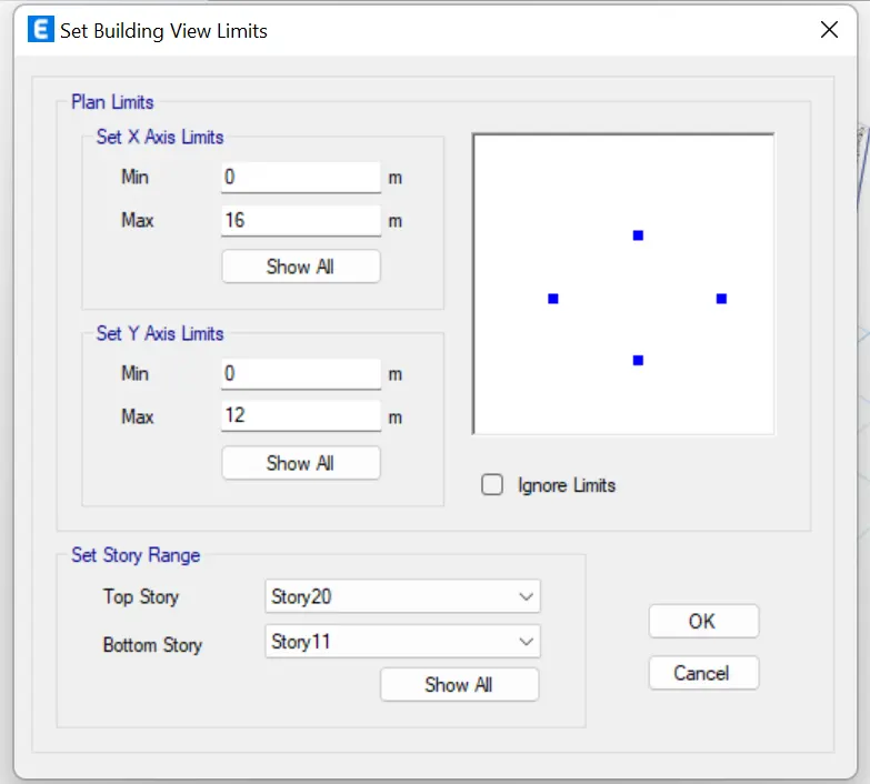
Now select the intermediate 10 storys.
by seting the building view limits.Then click on OK.
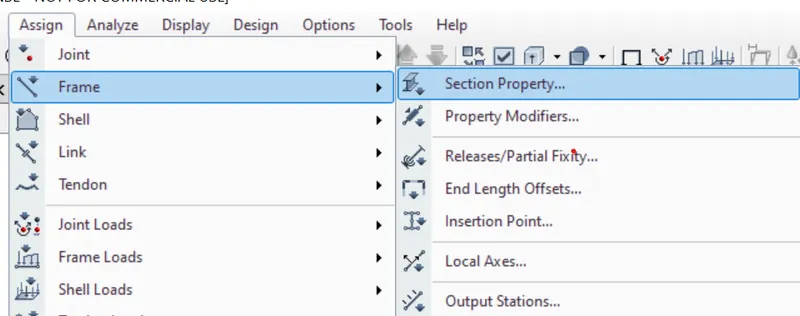
Then select all the columns then click on the assaign then click on the frame and then click on the sectional propeties.
Now click on the properties and then select .
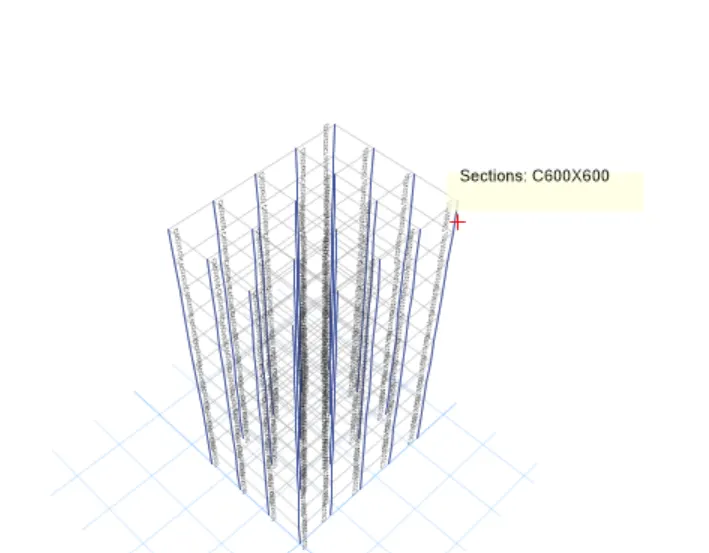
Now set back the building view limits to normal.
Then give the view of floors and the beams back to the building by selecting them.
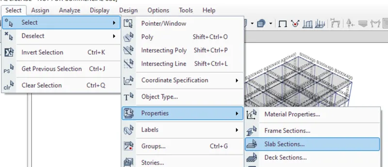
Now set the diapharme by clicking on the select then click on the propperties then click on the slab.
Now click on the assaign then click on the shell then diaphargms.
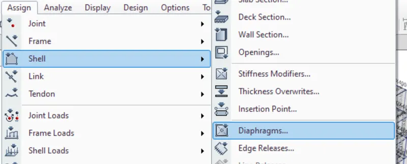
then we can see the cent of mass has been created.
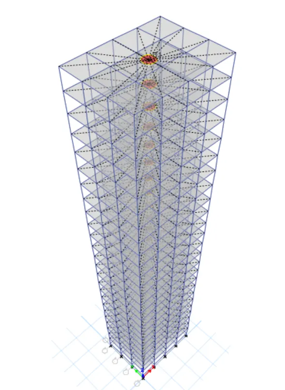
now click on the analyze then we can see the deflection.
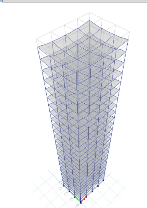
Model h:
In this model all the floor columns sizes are same.
now to change the column size. first we need to save the model as Model h by using save as.
Now click on the model vie type and then unmark the floors and the beams.
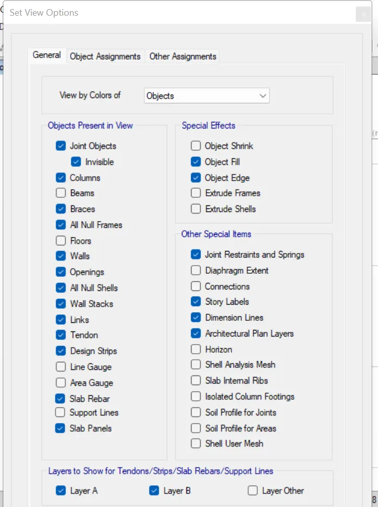
Now select all the columns by selection it by dragging it and then click on the asaign then click on the frame then click on the sectional properties.
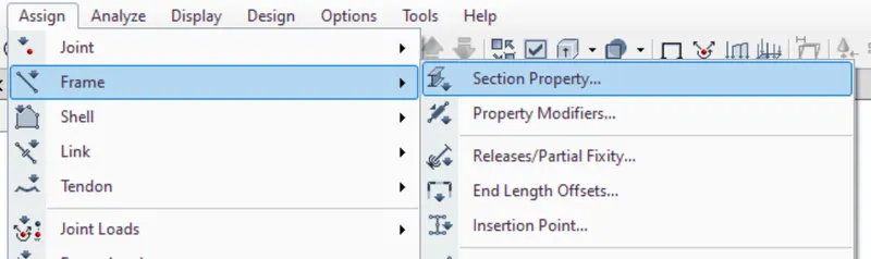
now after that we can see the all th colums has been with the same sizes.
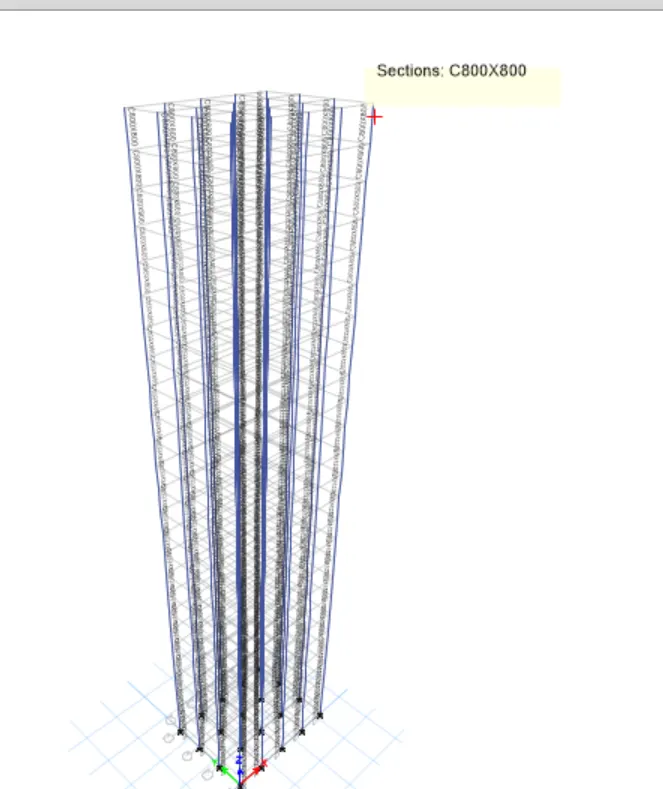
NOw unhide the floor and the beams by using the view point icon in the tab.
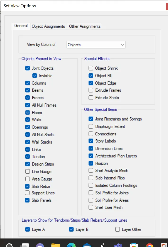
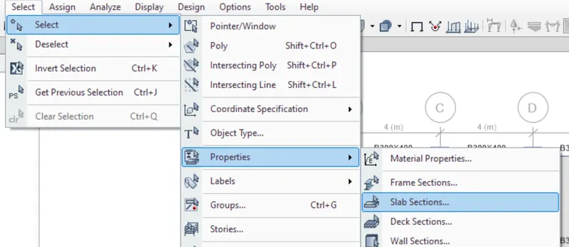
now to assaign the diaphagm. we nee to select the slab first.
first click on the select then click on the properties adn then slab.
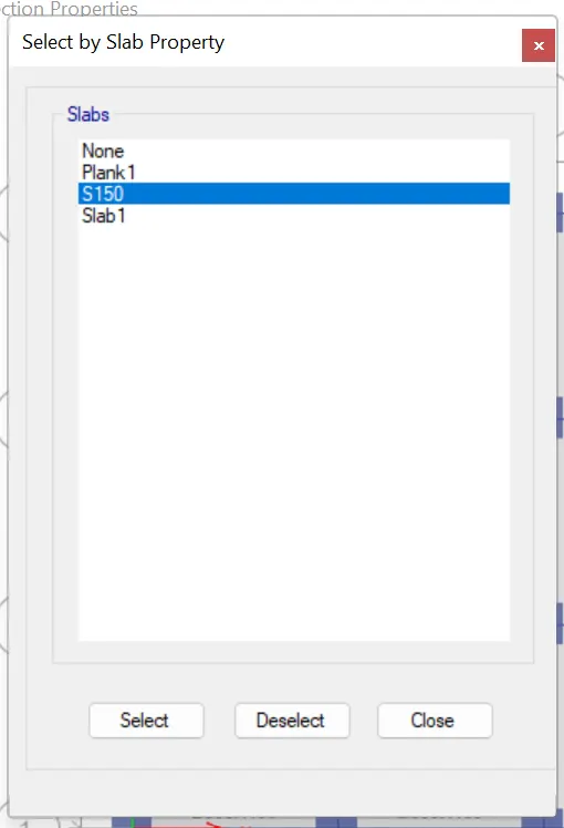
Now click on s150 and click on ok.
now click on assaign in ribbon then shell and then diaphagrm.
now we can see the diaphagrm has created.
Now click on analyze and the we can see the deflection of the building.
Model J:
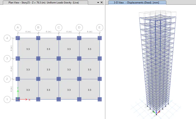
In the model J every thing is same as per the previous but they asked us to increase the 10% impost mass.
Now select all the floors by using the select option and then click on the properties then click on the slab.
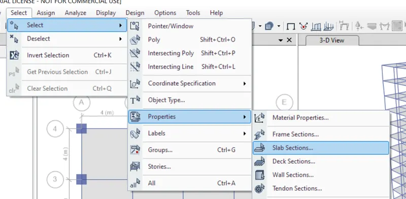
Now click on the s150 then click ok.
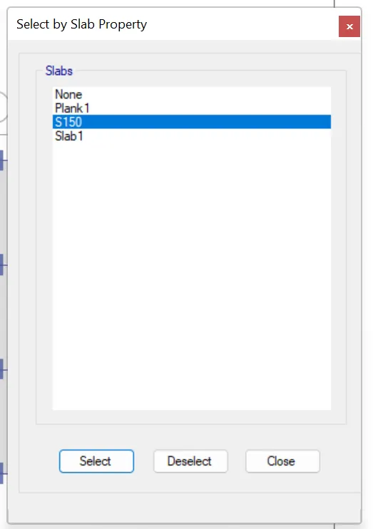
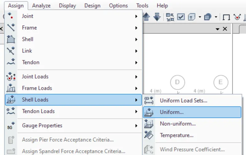
Now click on assaign then click on the shell loads then click on the uniform loads.
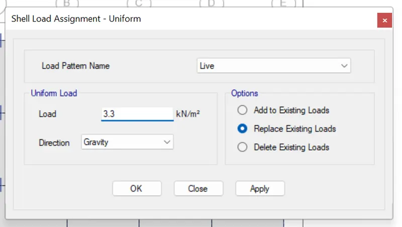
now increase it by 10% of the load.
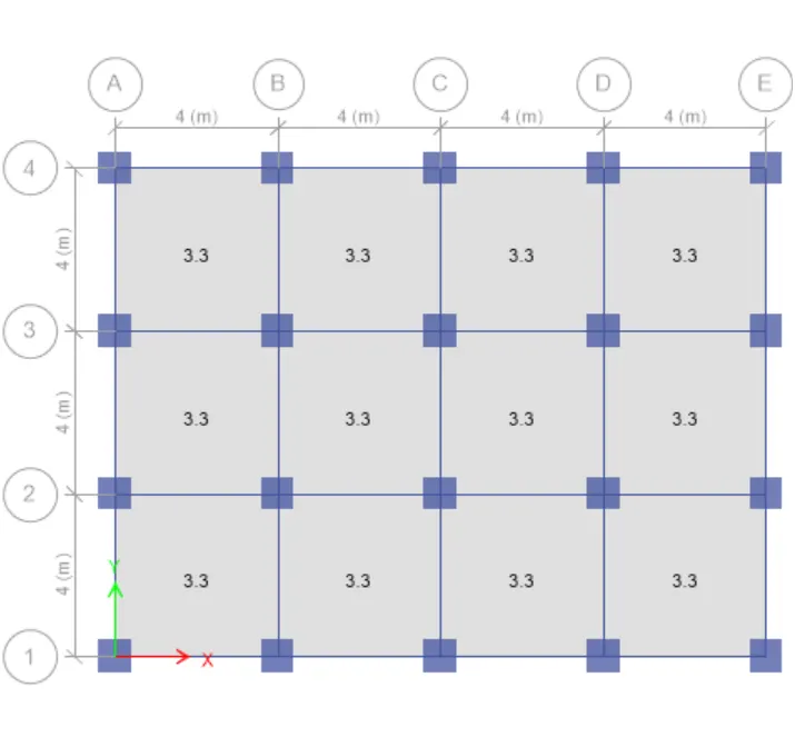
now we can see that mass has been increased in the model.
Then click on the run analysis then we can see the deflected shape in the model.
Model K:
In this model impost mass is increased by 20%.
We need to save teh previous file as Model K by using the save as option.
Now select all the floors by using the select option and then click on the properties then click on the slab.
Now click on the s150 then click ok.
Now click on assaign then click on the shell loads then click on the uniform loads.
now increase it by 20% of the load.
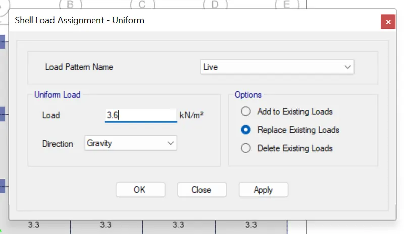
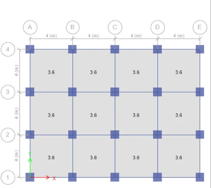
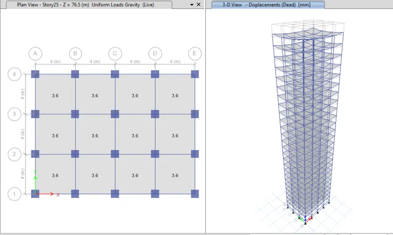
Now click on Apply and then click on OK. Now we can see the mass increase.
Now click on analyze then we can see the deflection.
Factors influencing the dynamic characteristics of a building
Factors influencing the Natural Period of a building
Factors influencing the Mode shape of oscillations