Project 1_Comparative study of different storey buildings for Seismic forces
AIM :
to model and analyze multiple buildings using ETABS software and compare the results of different storey buildings for seismic forces.
INTRODUCTION : objective of the project is to know how to extract different seismic responses for a structure, how to easily alter certain properties in an ETABS model, to factors influencing the dynamic characteristics of a building, to know the factors influencing the natural period of a building, to know the factors influencing the mode shape of oscillations.
PROCEDURE :
1.BUILDING-A (G+2)
Open ETABS and setup model
- open ETABS software
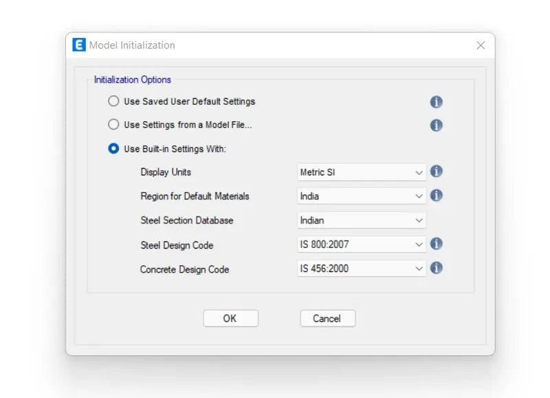
- click on the new model
- setup the units and codes
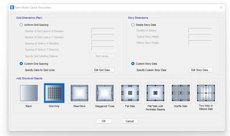
setting up the grid data :
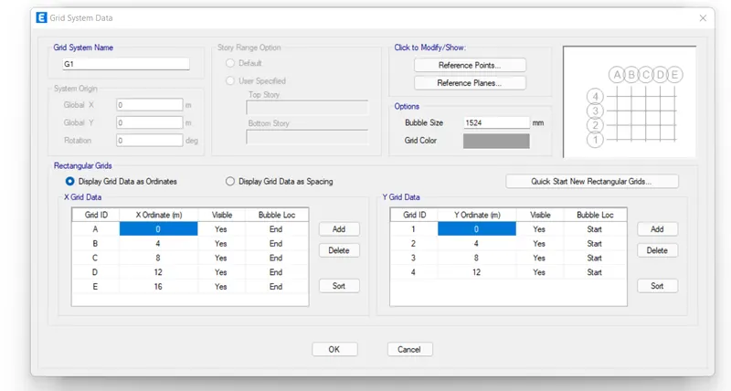
- click on the custom grid spacing and edit it
- fix the length, no. of grids in both the directions
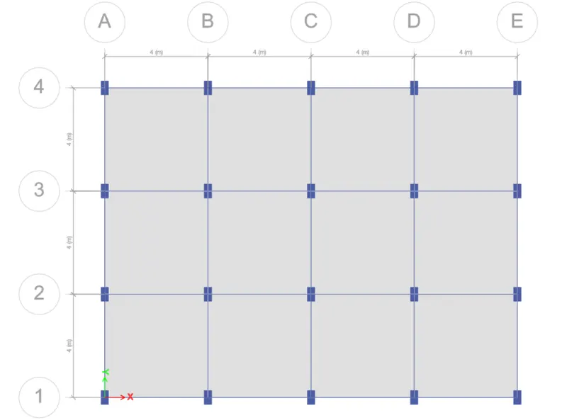
- 4grid points in x-direction and 3grid in y-direction, with 4m centre to centre spacing
fixing the storey data :
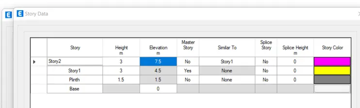
- specify the base level, plinth level, number of storey required.
- plinth heigth taken as1.5m and storey height as 3m
- specify storey-1 as master storey
defining the material properties :
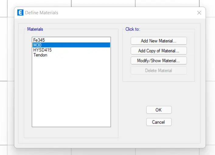
- we have used M30 grade concrete and fe415 HYSD steel
- go to define > click material properties > add new material > concrete and steel > press ok
defining section properties :
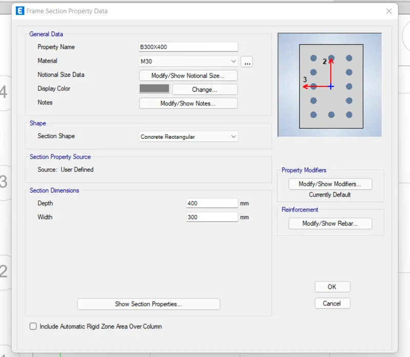
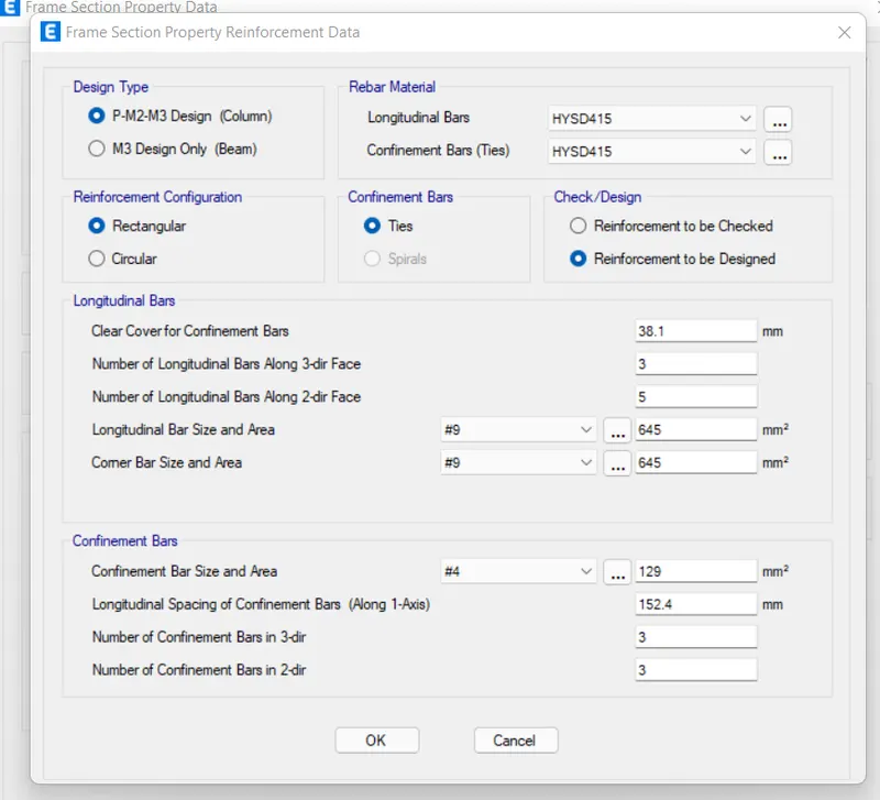
- we have used rectangular concrete section for beams and columns.
- go to define > section properties > frame section > add new property > select rectangular section for beam
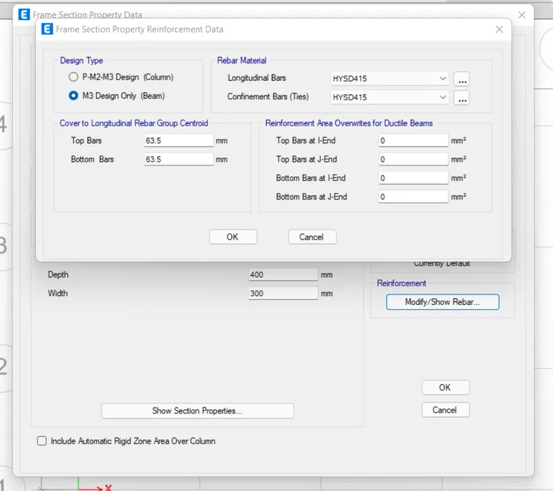
- provide material as M30 concrete and reinforcement Fe415 HYSD steel
- desgin type as M3 design only
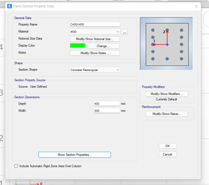
- repeat the same procedure for columns except design type will be P-M2-M3 dessign
BEAM 300x400
for columns 400x400
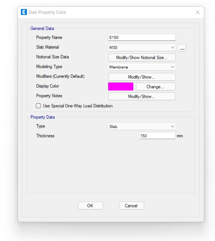
for slab 150
- we have provided slab with 150mm thicknesss
- go to define > section properties > slab section > add new property
execute the modelling :
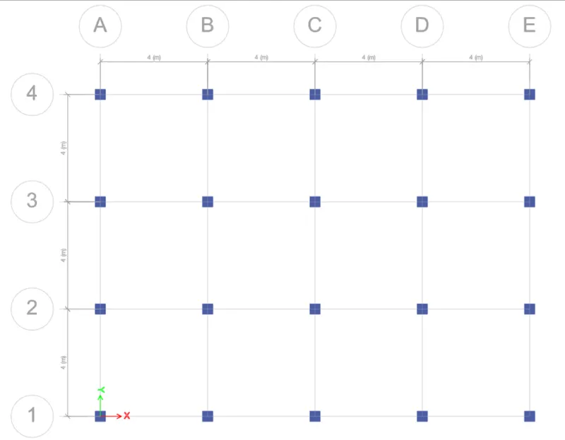
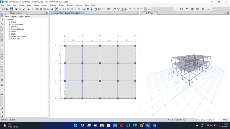
- after assigning the material properties now draw the columns, beams and slabs
- use quick draw option tool
- select quick draw column > select the property of column
- draw the columns on grid intersection
- use quick draw beam tool and draw the beams
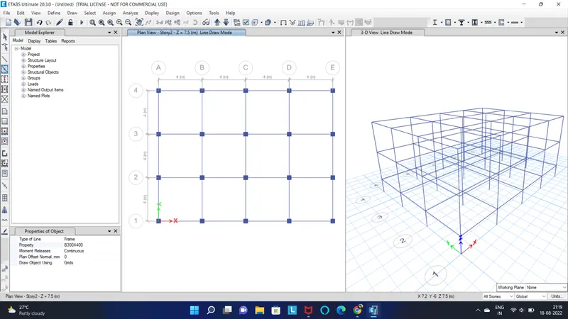
- use quick draw floor tools to draw the slabs
define the load patterns :
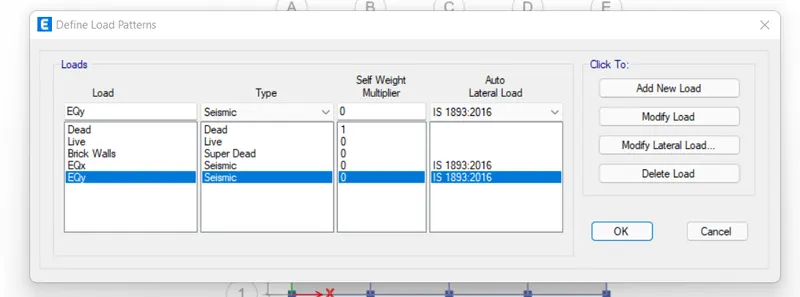
- we have added dead load,live load, wall load (super dead load), earthquake load in x and y direction.
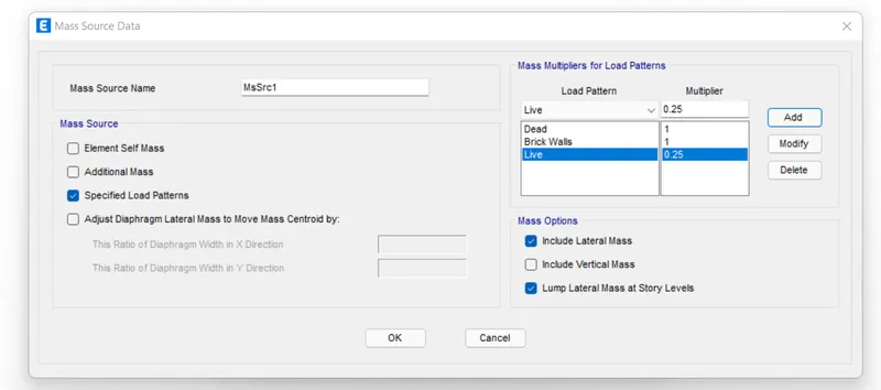
- we defined the mass source by adding 100% of dead and super dead load as well as 25% of the imposed or live load.
- 
generate the load combinations :
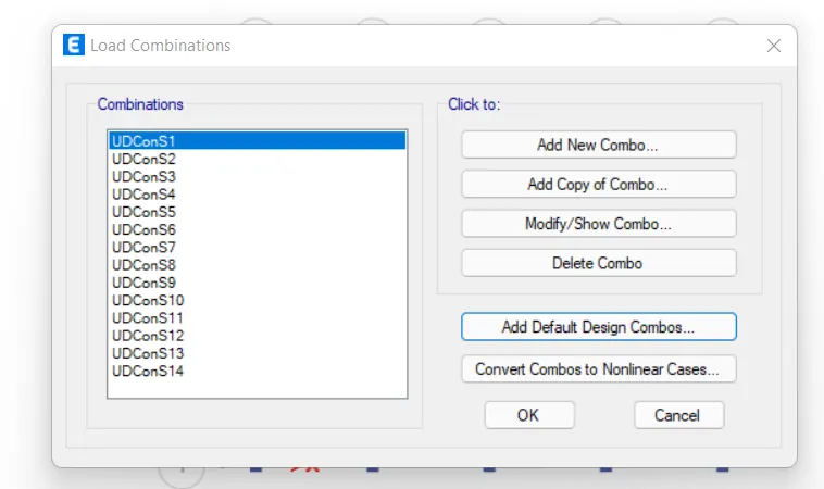
- go to define > load combinations > select add default design combo> select concrete frame design and convert to user combination > press ok
assign load to structural member :
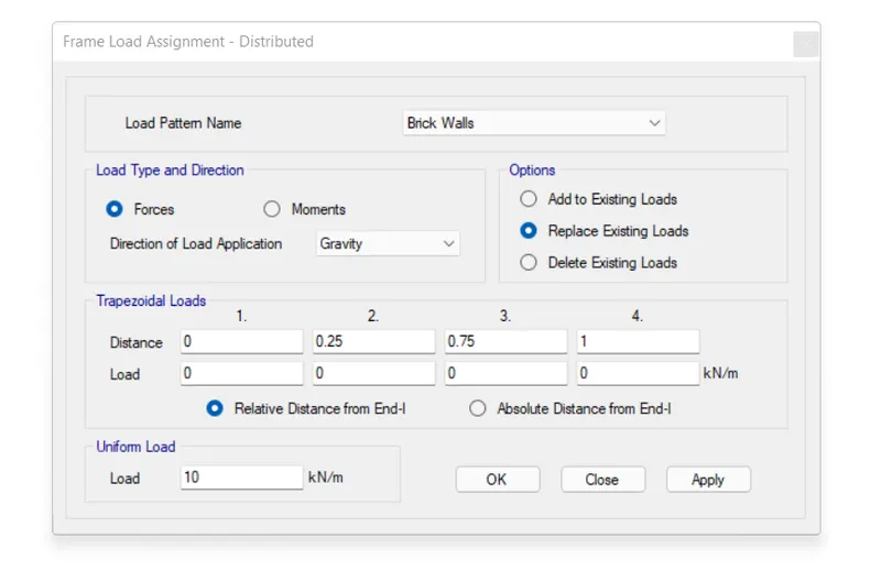
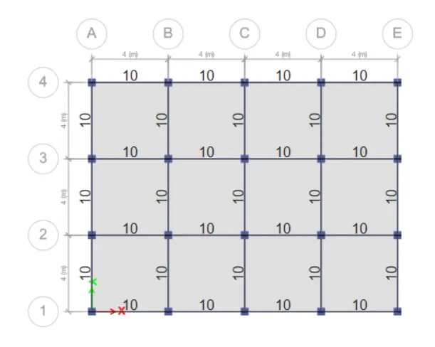
- select the beam and assign a udl super dead load due to brickwalls on beam
- go to select > select >properties > frame section> select beam
- go to assign > select frame load > distributed
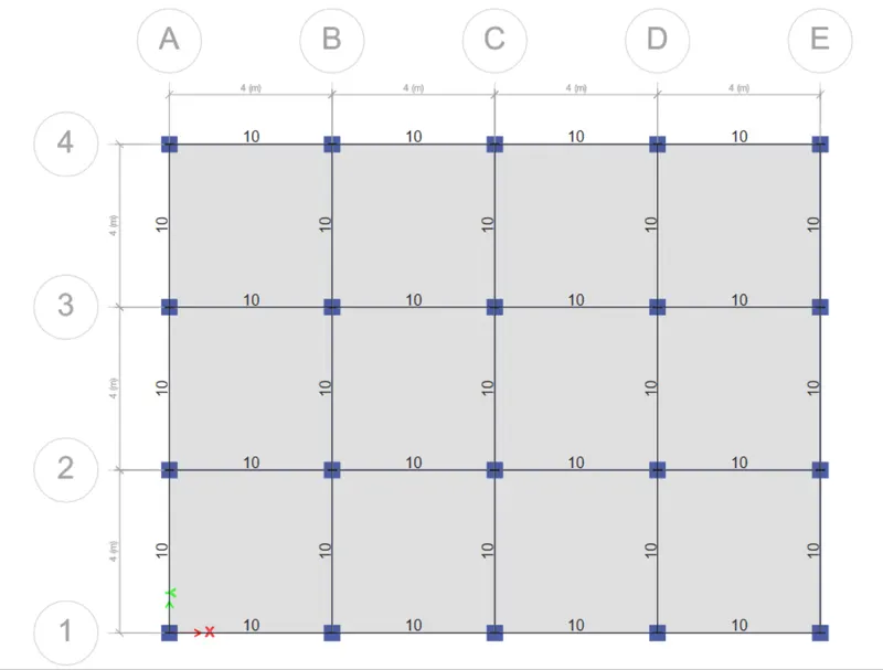
10kn/m load on beam
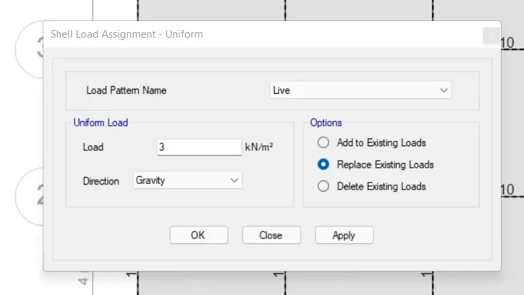
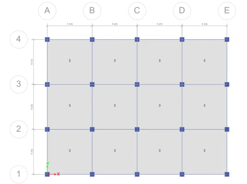
3kn/m live load
assign the floor diaphragm
- select slab 150 and assign the diphragms
- go to assign >shell > diphragms
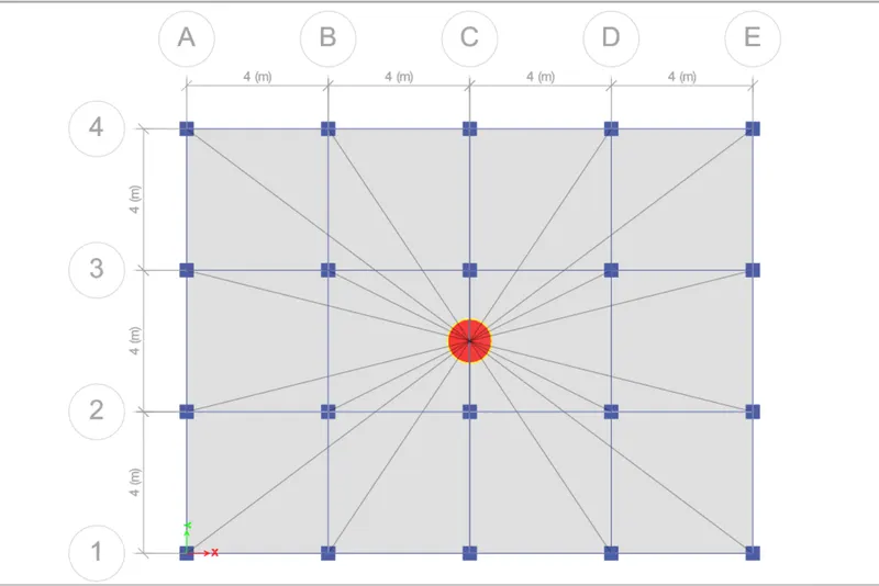
run analysis and save the model
- click the symbol of run analyis and get result
- after that save the model
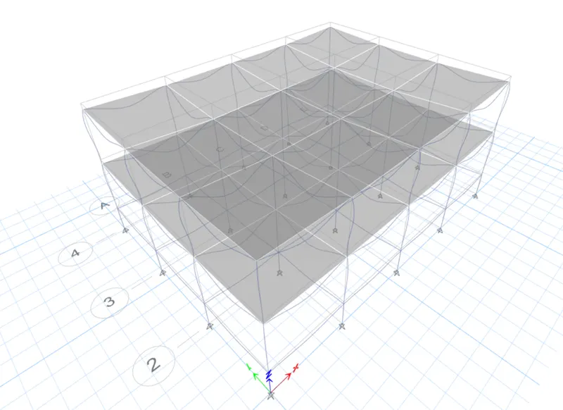
2. BULDING-B(G+5)
- in this model we need to increase the number of storey i.e 5 number of storeys.
- Now to model building B, we need not create a new ETABS file from scratch. just copy the buiding-A file using save as options and do the alteration as needed.
go to file > save as > select destination folder > name as MODEL-B
increasing the storey
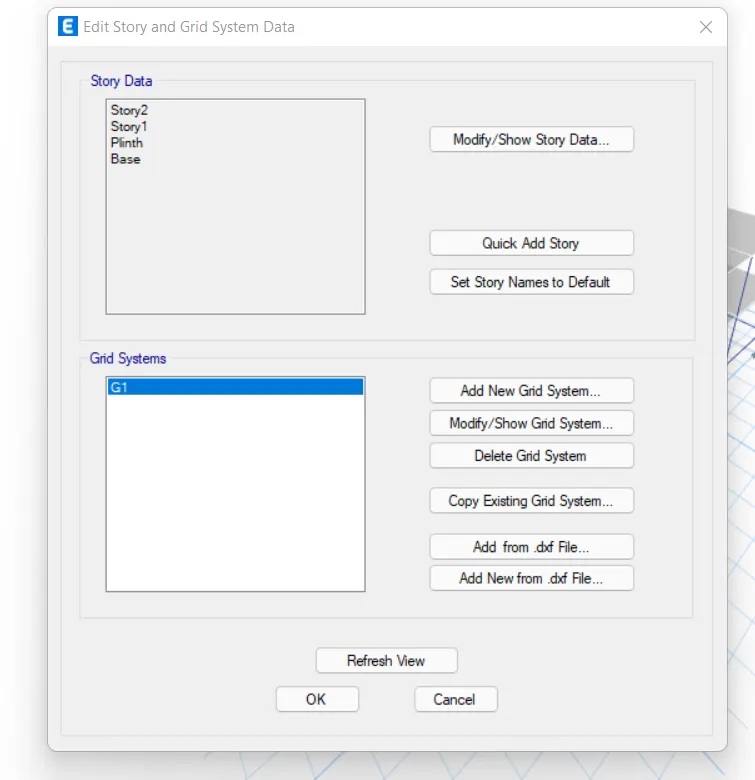
- go to edit > select edit stories and grid systems > modify show story data
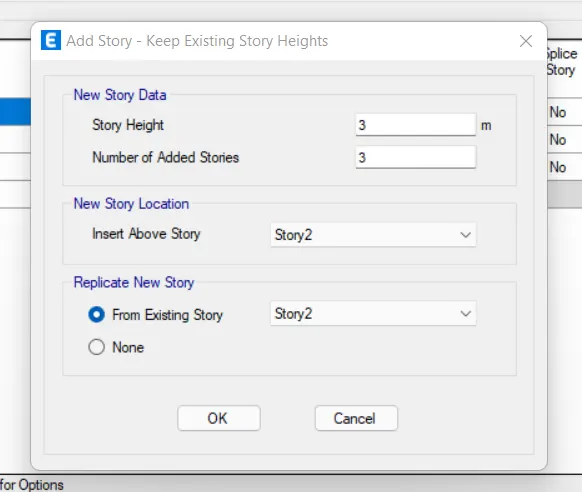
- so we ahve already 2 storey in model for 5 storey we need to increase 3 storey more
- so type 3 in number of added storey
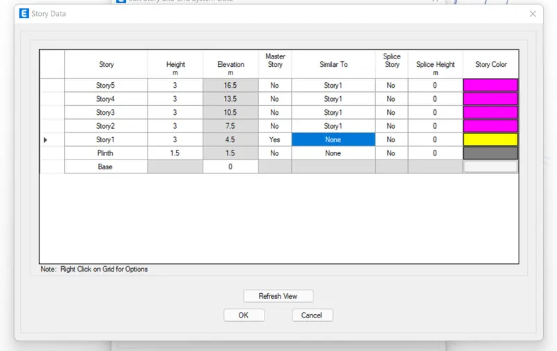
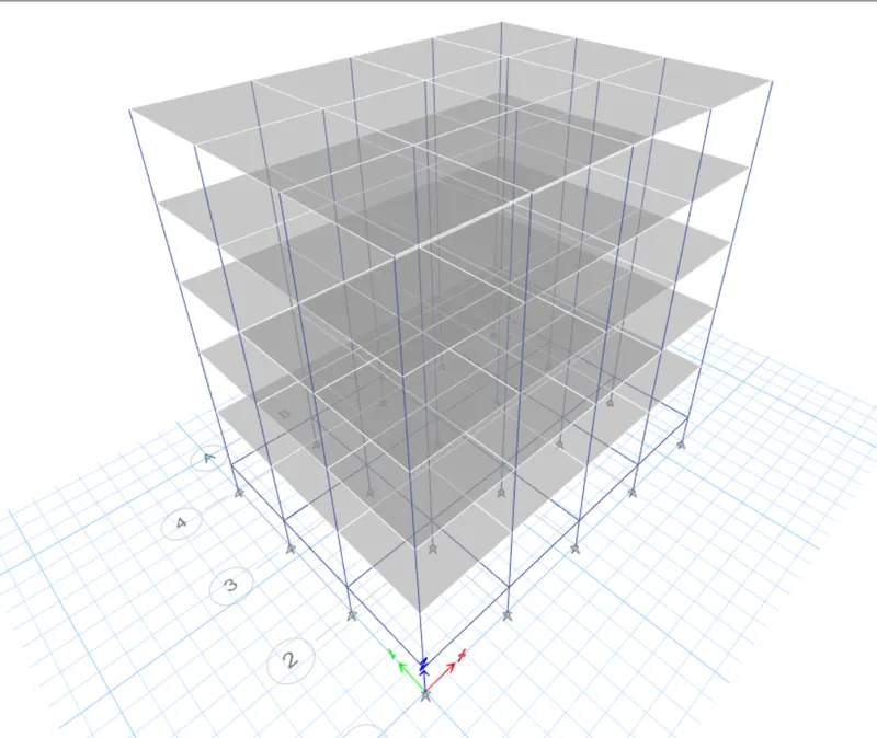
check the model before run analysis
- check for live load, wall load etc
- check for diaphragms also
- now go to run analysis
- it will take few seconds to obtain results
check for shell loads
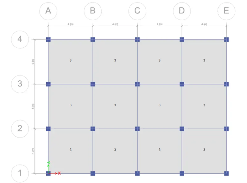
check for frame loads
diaphragms check
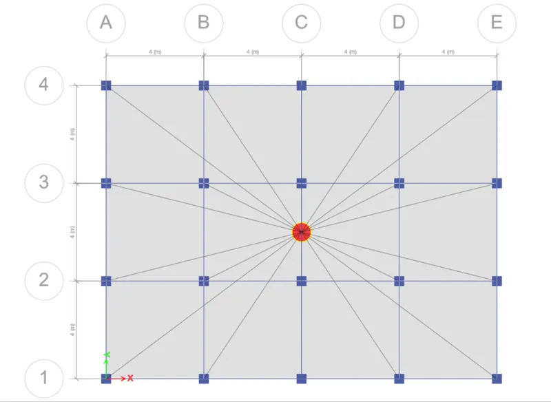
run analysis
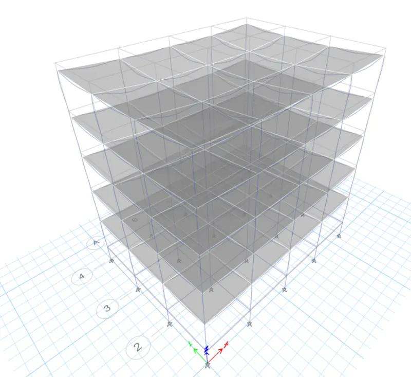
3.Building-C (G+5, rectangular columns oriented along x-direction)
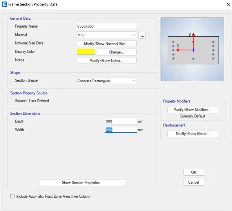
- in this model we need to change column size as 550x300 and orient the same in x-direction.
- story and grid data will remain same.
copy the model using save as
- go to file> save as > select destination folder > name the model-C
- model is set to edited
edit the column size and orientation
- go to define > section properties > frame section
- change the property name as required and provide depth and width of column
- we need to orient the 550 in x-direction
- go to assign > frame >local axes > angle as 90degree > press apply and ok
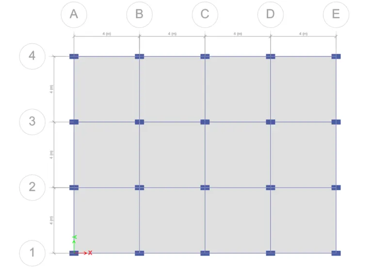
check for loading and run analysis
- check for shell load, frame loads and diphragms as we did in previous model
- after checking go for run analysis
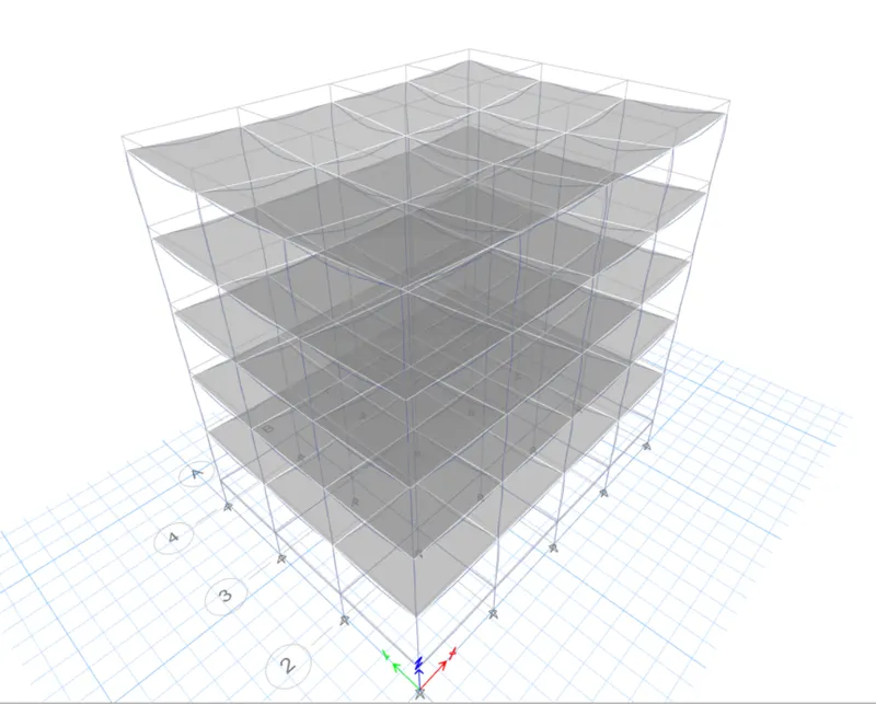
4. Building-D
- rectangular column oriented along-y direction
- in this model we dont need to alter anything rather than column orientation
- so follow the same procedure as we did in previous model
- save as file with name model-D
- go to assign > frame > local axes > make angle as 0 degree
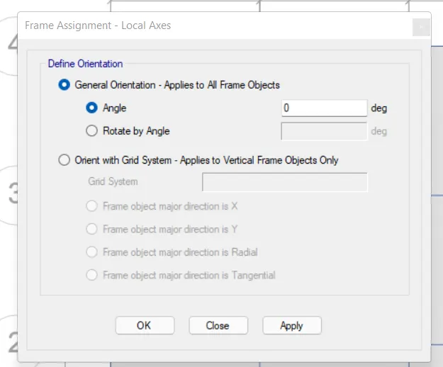
Run analysis
- check for loading and diphragms before analysis
- and run analysis
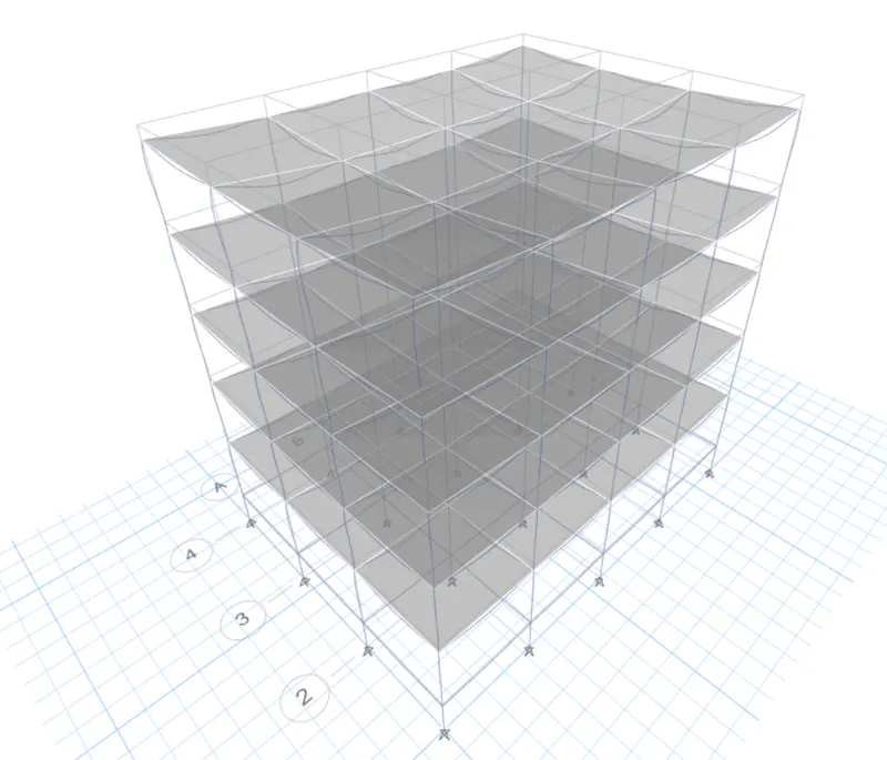
5.Building-E
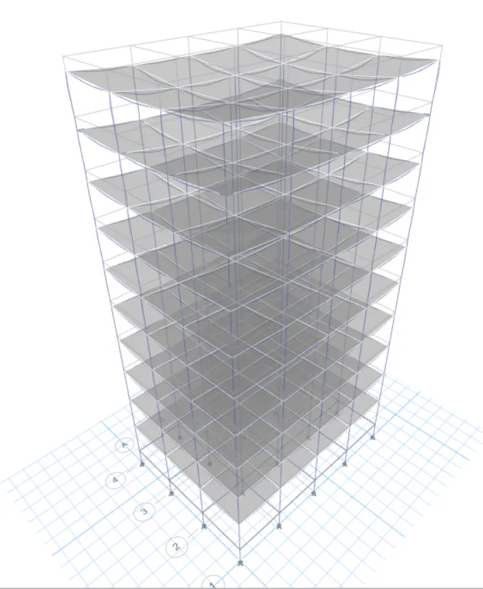
number of storey-10
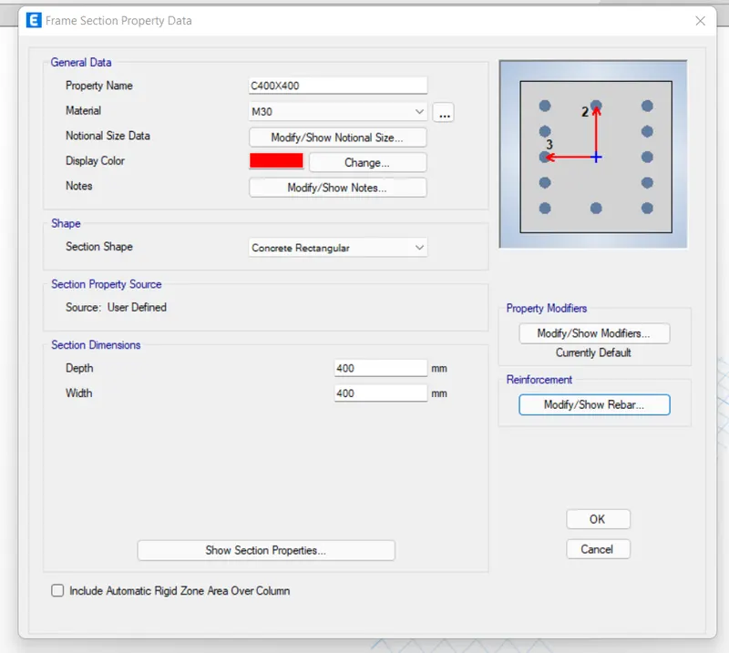
upper 5 storey column size 400x400
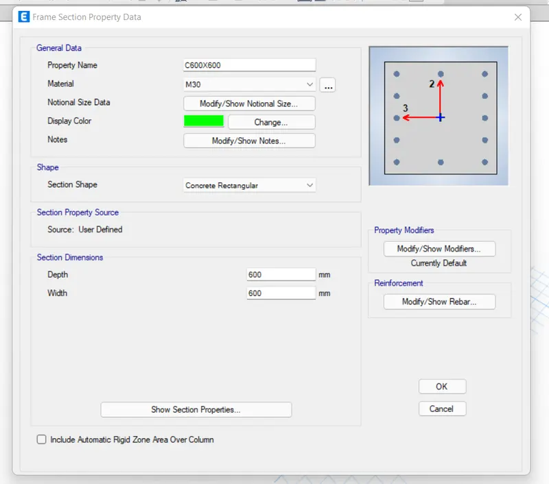
bottom 5 storey column size 600x600
- using save as save the file in destination folder with name model-E
add stories in modelling
- go to edit > edit stories and grid system > modify/show storey data > add storey 5
- we ahve already 5 store model so add just 5 storey
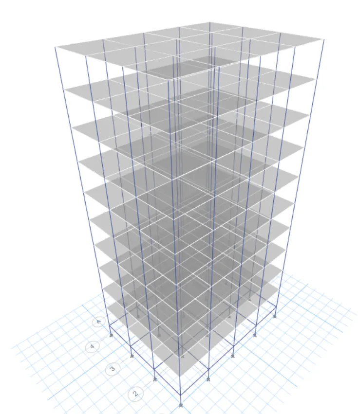
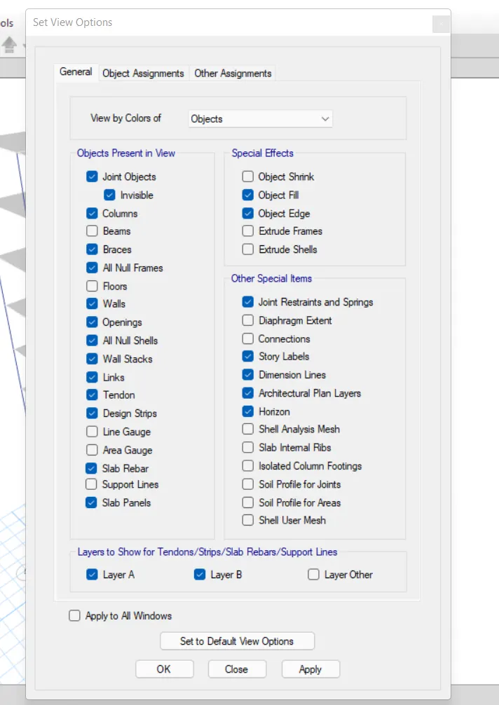
change the view setting of the model :
- first we need to hide beams and floors to modify the column
- go to view > set display option > uncheck beams and floors >uncheck layer other > press ok
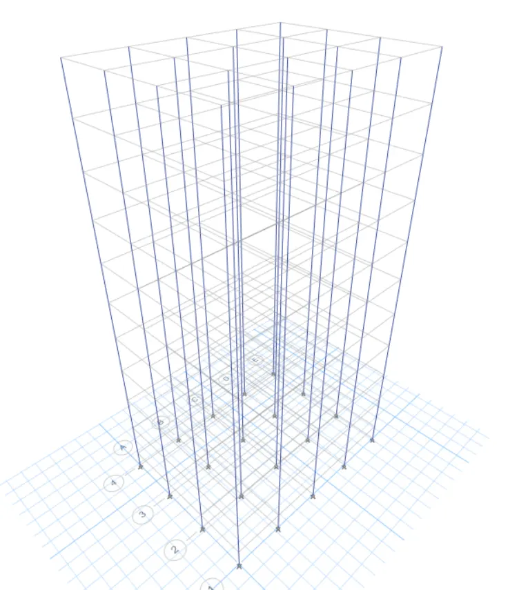
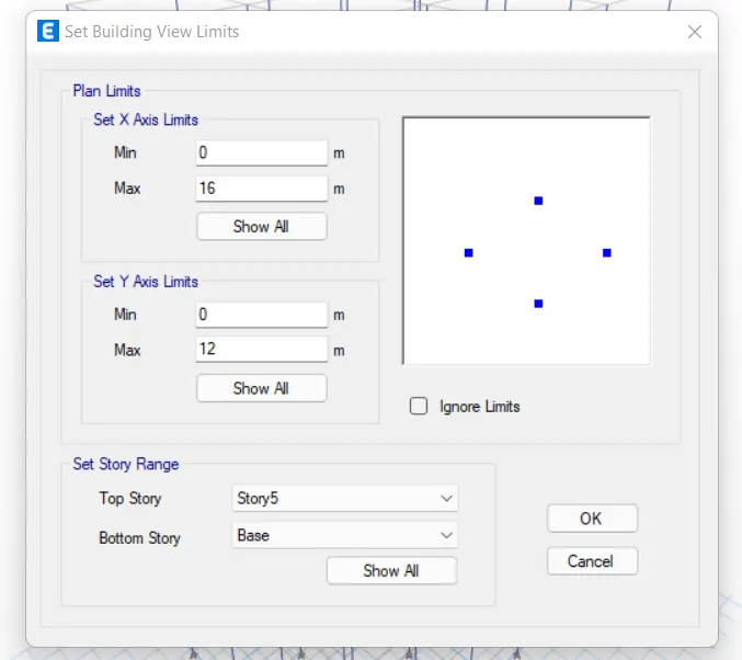
set the building limits, select columns, assign them the required sections :
- we need to modify column sizes for top5 storey and bottom storey
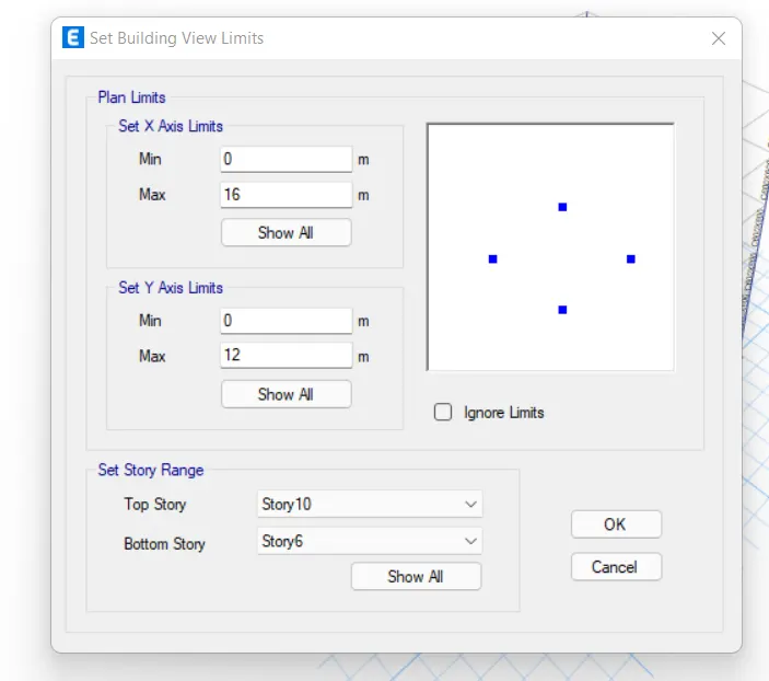
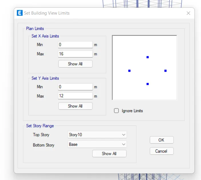
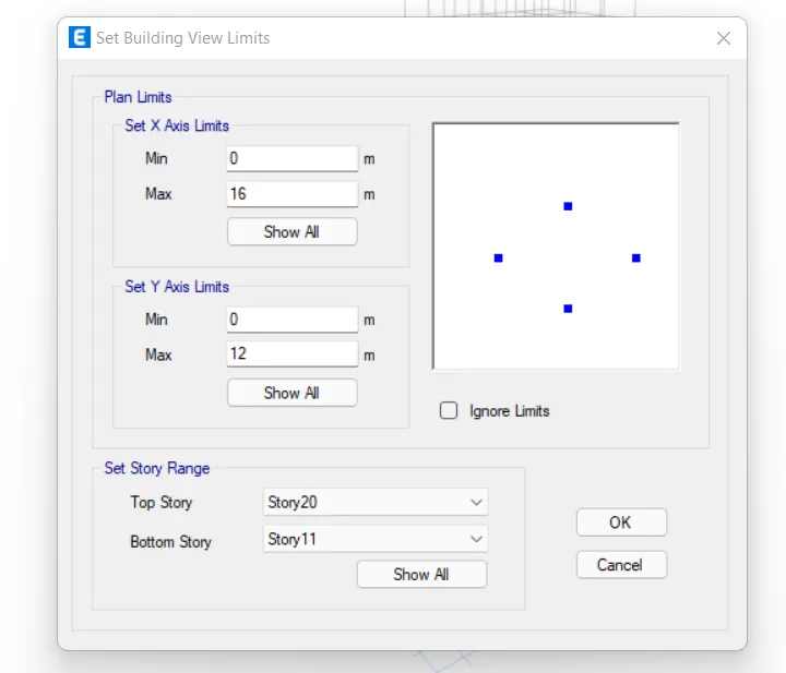
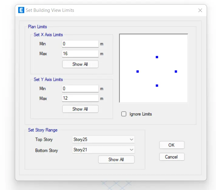
- go to view > set building view limits > edit the box
- the set building limits option allows you to view only the floors that you need to work on
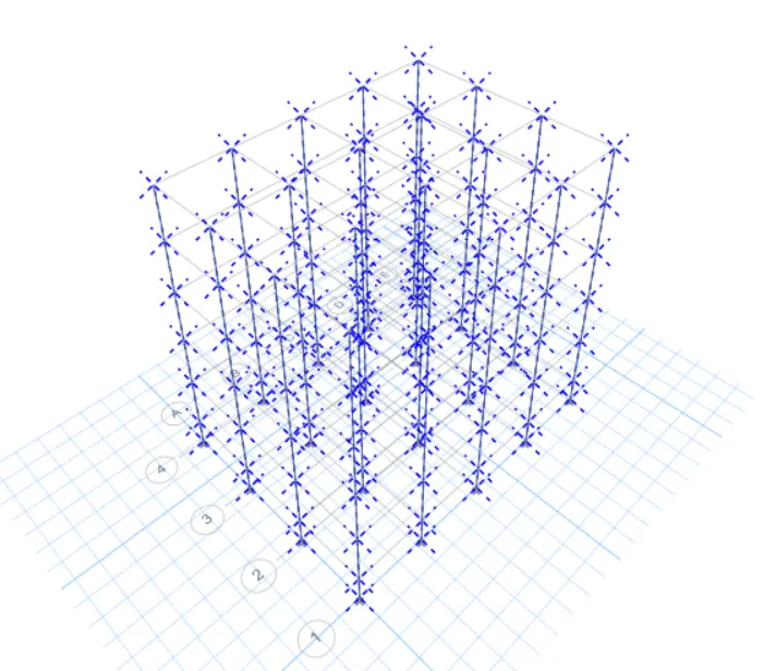
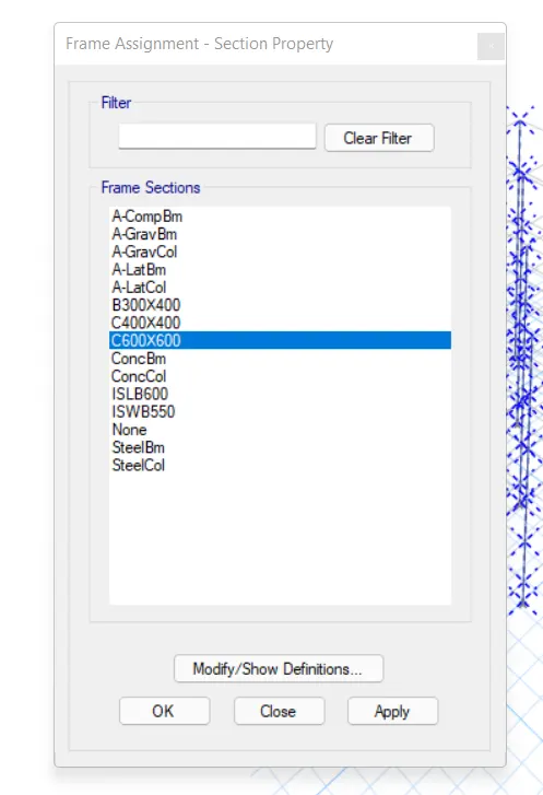
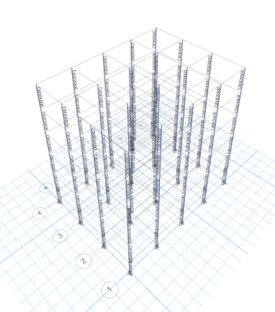
- first set the limit to bottom 5> select all columns by holding the left click and making the box around the entire model > go to assign and assign them the required column section
- repeat the procedure fot top columns
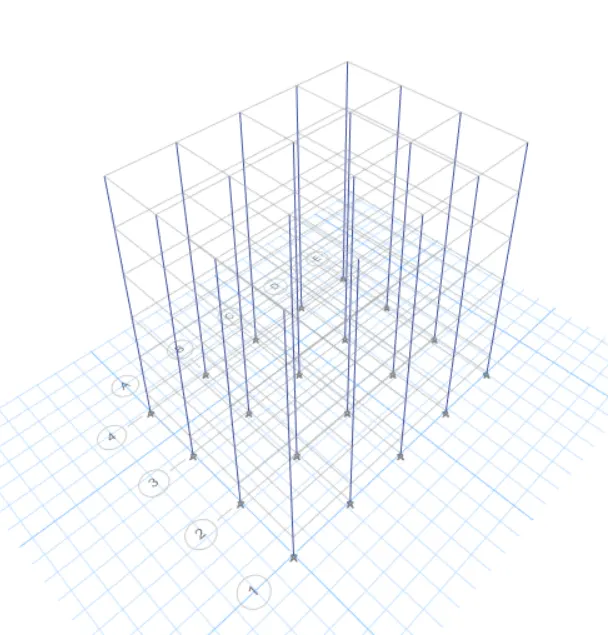
building limits
C 400X400
C600 x600
select bottom 5 storey column
assign C600x600
building limits for top5 storeis
select all columns and assign them column C400x400 section
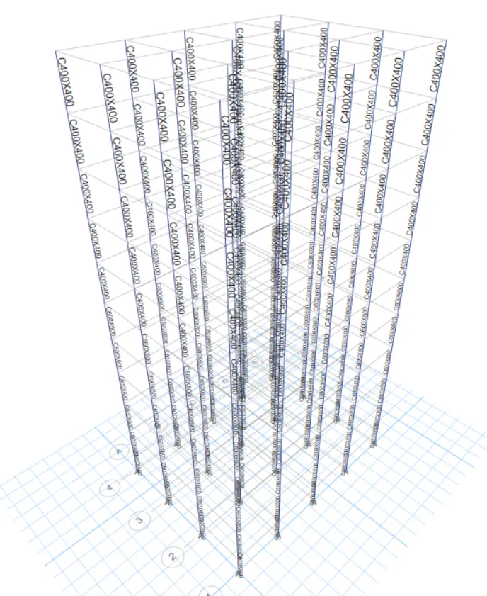
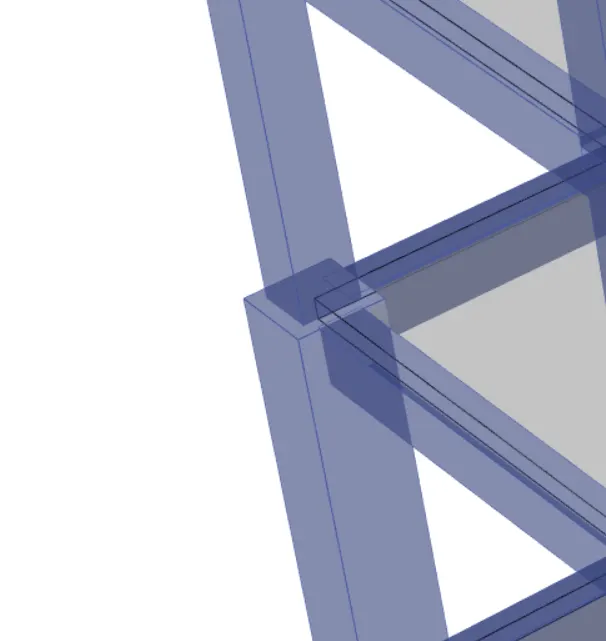
Run the analysis
6. Building-F
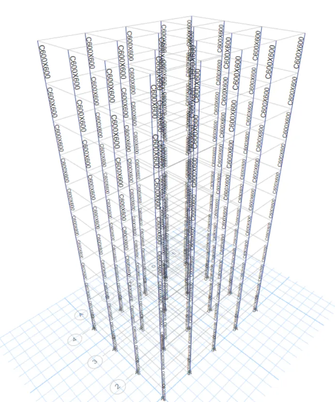
consistenet column size through out the structure C600X600
- The building has same columns for entire structure. therfore, we dont need to do much editing in terms of seections. we just need to adjust the view setting > hide beams and floors > select all the columns > assign them the frame section properties of C400x400
adjust view option setting :
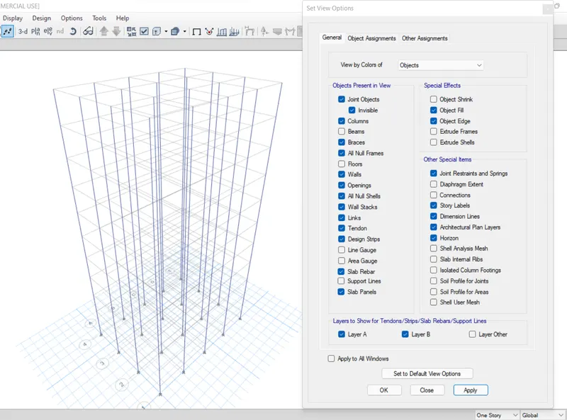
select all the columns :
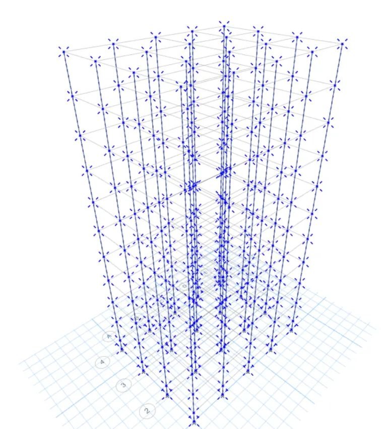
Assign C600x600
7.Building G (G+25)
column for top 5 stories : C400X400
column for middle 10 stories :C600x600
Columns for bottom 10 storeis : C800x800
- for this model we need to add 15 new stories and assign different column sizes on different floors. we can follow the exact procedure that has already been explained for the previous project to create this model by editing building F. the same is discussed below.
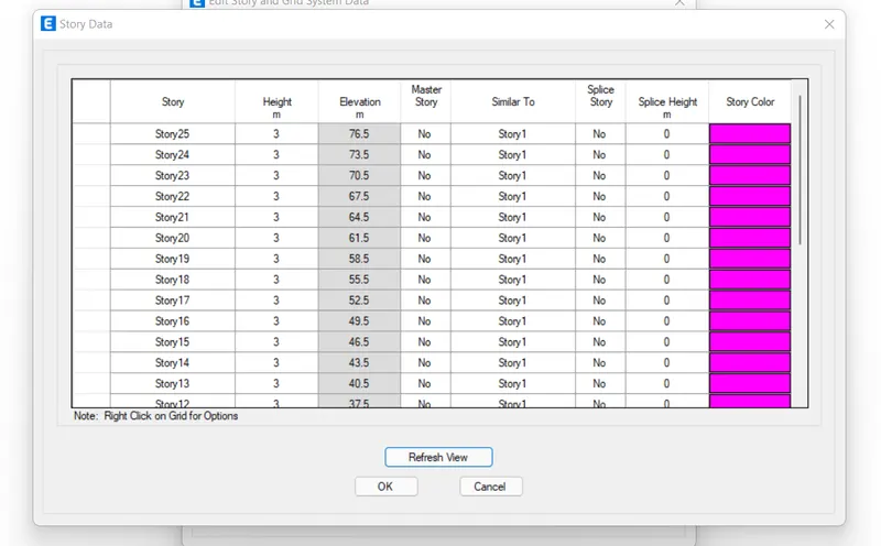
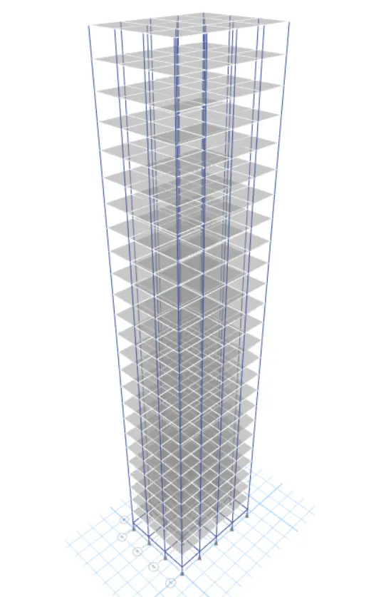
View setting :
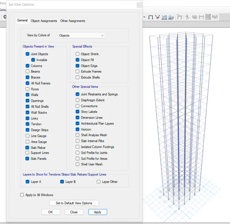
set building limits from 1 to 10
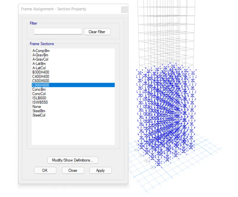
select all the columns and assign C800x800 section
set building limit 11-20
set building limit 20 to 25
select all the columns and assign C400x400
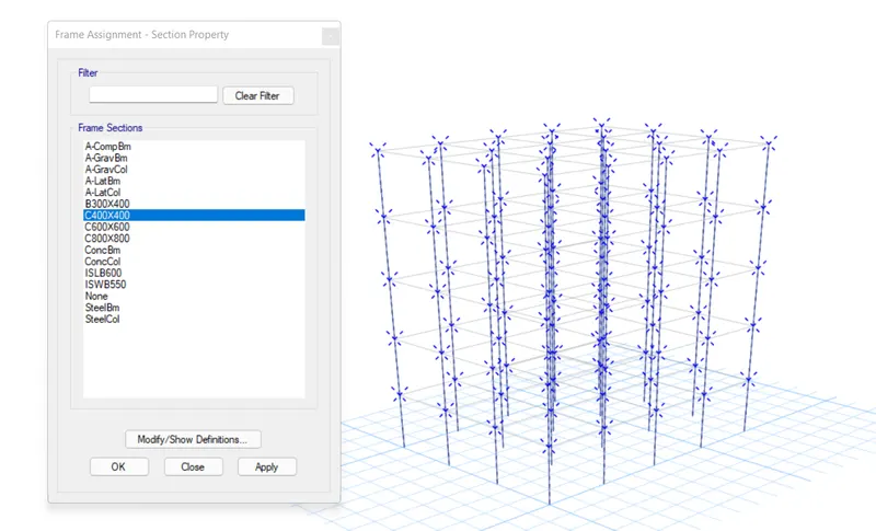
run the analysis
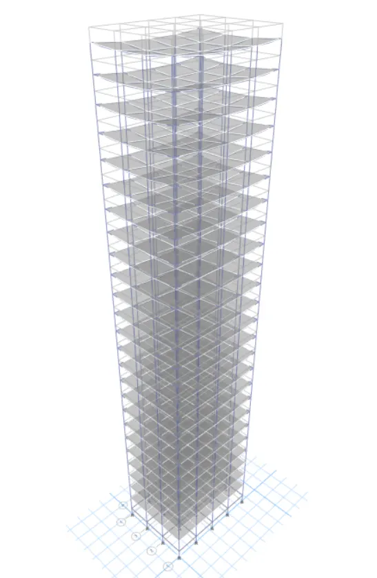
Building -H (G+25)
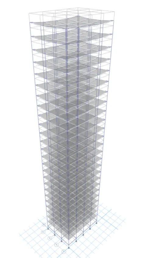
consistent column size throughout the building: C800x800
- this is the same model as the previous one.all we need to do is assign the column section as C800x800 for the entire structure which can be done by simmply selecting all the columns > go to assign > select C800x800 > click ok. thus the same procedure is listed down below for better understanding.
view setting to hide beams and floors
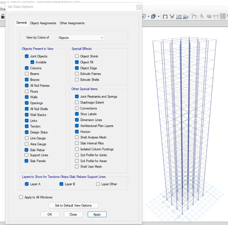
select all the columns and assign C800x800 section
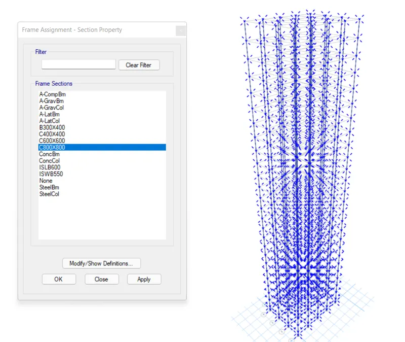
Run the analysis
9. building J(G+25)
10% increment in the imposed loads.
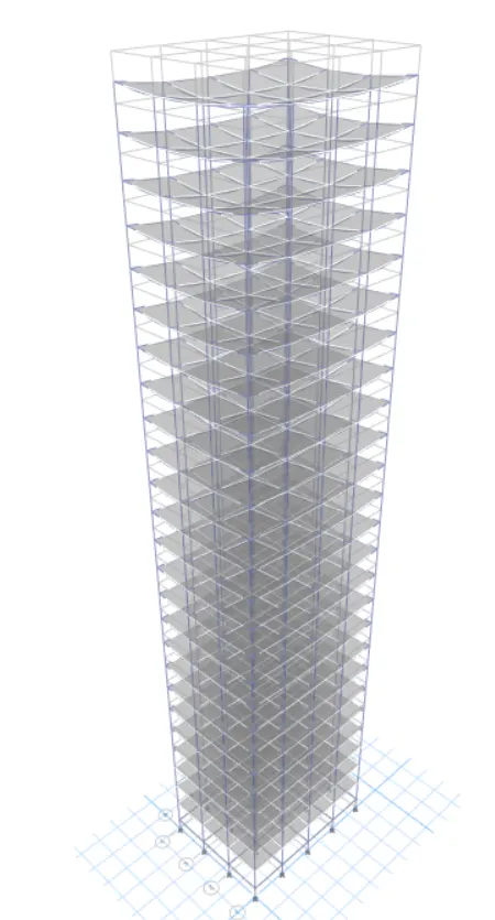
- building J is the exact copy of the model H and we dont need to alter anything related to the modelling. however we need to increase the imposed load on the building by 10% which is assigned as 3kn/m^2 on all slabs of the building. so the procedure to do the same is listed down below.
select the S150 slab section
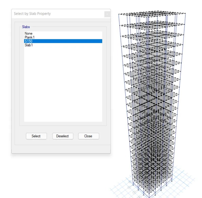
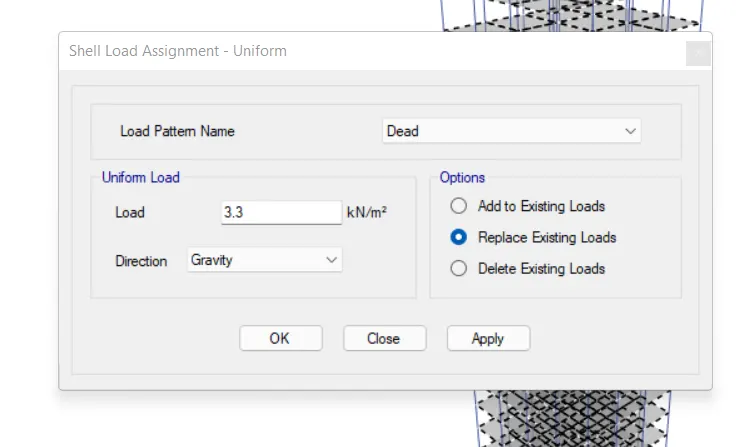
go to assign > shell loads> uniform > increase it by 10%
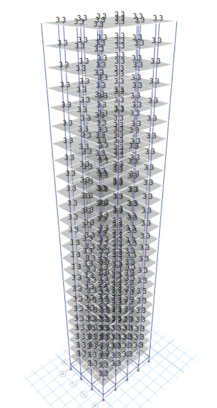
- we have assigned a 3kn/m^2 imposed load on all the slabs for all of our previous buildings.
- so we need to increase that by 10% meaning we need to replace the existing imposed load with 3.3kn/m^2
run the analysis
Building-K (G+25)
20% Increment in the imposed loads.
- for this model, we can follow exact procedure as we did for a building J. however this time we need to increase th live load by 20% as opposed to 10%
select s150 slab section
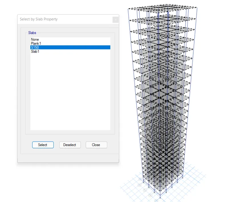
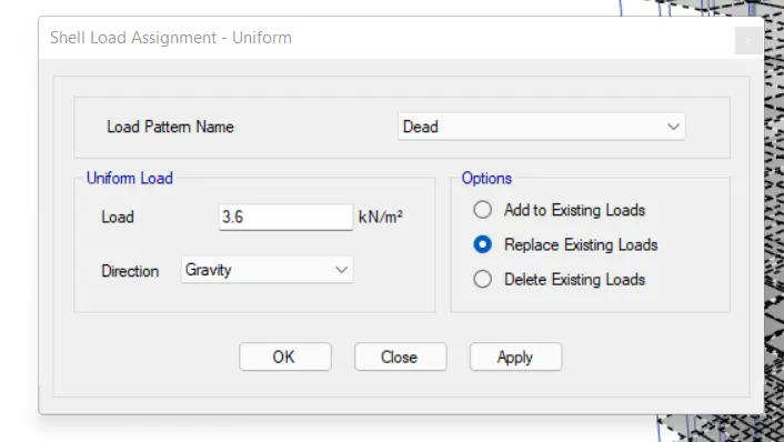
assign 3.6kn/m^2 distributed shell loads for a 20% increase
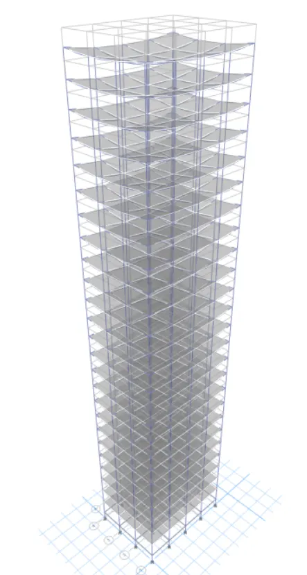
run the analysis
COMPARATIVE ANALYSIS FOR SEISMIC FORCES
- Open the model which we have saved > go to model explorer > tables > analysis result > structure output
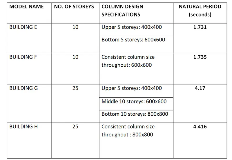
Effect of stiffness on T : compare fundamental natural periods of building E and F as well as G and H. Why is there a marginal or significant difference in the fundamental natural periods ?
conclusion:
for building E and F, varying column design doesnt make big difference. however we can see that for building G and H the consistent column size throughout the structure causes a more natural period. therefore it can be concluded that providing larger columns at the base and then reducing the size on top floors helps control the natural periods 'T' for building.
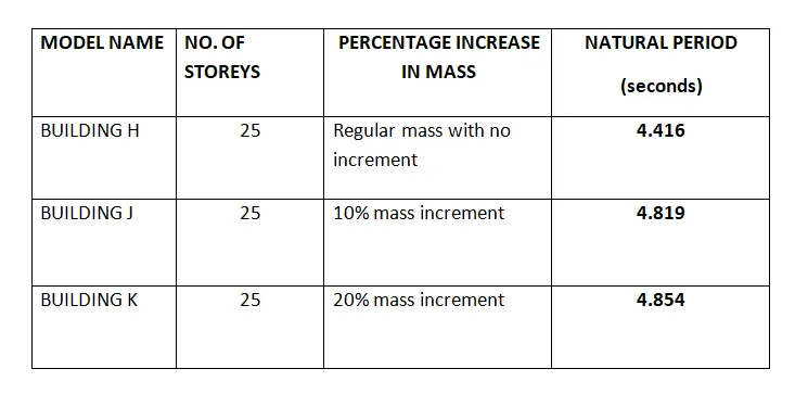
Effect of mass on T : compare fundamental natural periods of building H,J and K. Have the building becomes more flexible and stiff due to change in mass ?
Conclusion :
as seen from the table, the natural period for the building is directly proportional to the imposed mass of the building.
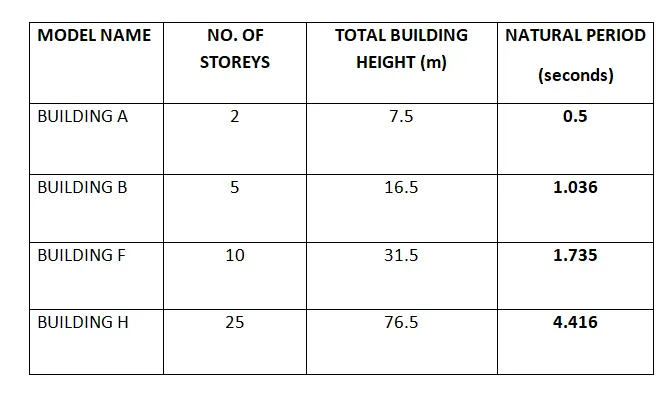
Effect of building height on T: how do the fundmental natural periods of buildings A,B,F AND H change with change in building heights?
conclusion :
as indicated in the above table, the natural period T is also directly proportional to the building heights.
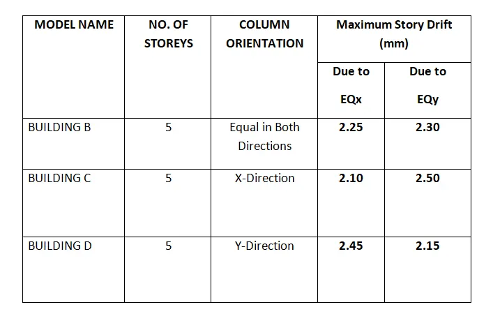
Effect of column orientation on T : how do the fundamental natural period of buildindgs B,C and D change with a change in column orientation?
conclusion :
when the column cross section are square, there is not so much difference between the lateral displacement in both orthogonal directions. however when you orient the column in a particular direction be it x and y the lateral displacement in that particular direction will be less than that in the other direction which has lesser column length.
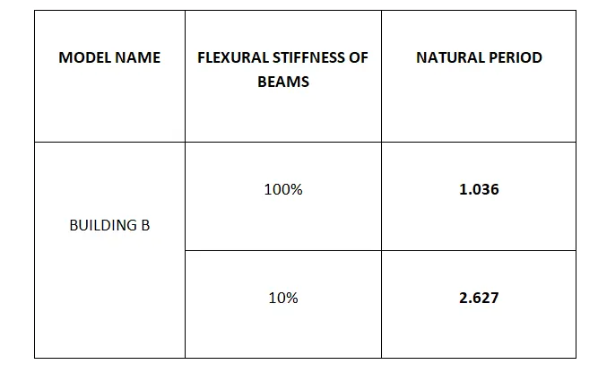
Effect of flexural stiffness of structural elements on mode shapes : compare fundamental modes shape of building B in two situations when the flexural stiffness of beam relative to that of adjoining columns is very small versus when it is large.
conclusion :
it is obivious that if you decrease the flexural stiffness of beam, the overall flexural strength of the beam is also going to reduce and consequently the fundamental natural periods will shoor up.
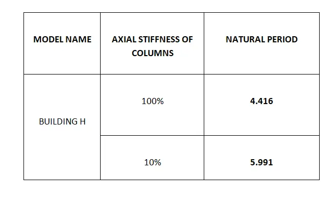
Effect of axial stiffness of vertical members on mode shapes : compare the fundamental mode shape of building H in two situations when the axial cross sectional area of column is very small versus when it is large.
conclusion :
as the axial stiffnes of columns deccreases the fundamnetal natural periods of the building increases regradless of its structural geometry.
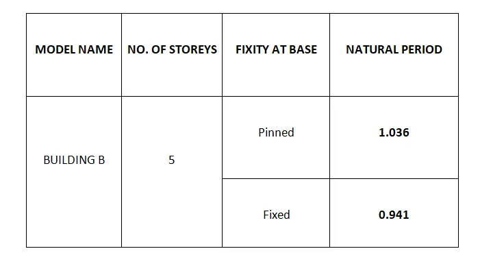
Effect of degree of fixity at columns base on mode shape : compare the fundamental mode shape of building B in two situations when the base of column is pinned versus when it is fixed
conclusions :
it is evident that pinned support offer fewer restraints compare to the fixed one which leads to more movements and thus increased natural periosds. as a result it can be concluded that the fixed support will give you better control over the fundamnetal natural periods of buildingd