Project 1_Comparative study of different storey buildings for Seismic forces
1.Ans
AIM: - TO STUDY AND COMPAIR THE RESULTS ON,
- Factors influencing the dynamic characteristics of different storey building for seismic force
- Factors influencing the Natural Period of different storey building for seismic force
- Factors influencing the Mode shape of oscillations of different storey building for seismic force
INTRODUCTION
- Every building offers a minimum resistance to the forces induced by the external effects like earthquake.
- The important dynamic characteristics of a building are the modes of oscillation and damping. Thus, it has effect of,
- Flexural Stiffness of Structural Elements on mode shapes
- Axial Stiffness of Vertical Members on mode shapes
- Degree of Fixity at column bases on mode shape
Data assumed are:
Material Properties
- Grade of Concrete: M30
- Grade of Steel Reinforcement Bars: Fe 415
Structural Element Sizes
- Beams: 300 x 400 mm
- Columns: (GIVEN IN TABLE) for different models
- Slab: 150 mm thick
Loading
- Live load on floor: 3 KN/m2
- Brick wall Load on beams: 10 KN/m
Buildings are assumed to be pinned at base
PROCEDURE:
GENERAL PROCEDURE FOR DESIGNING ALL THE REQUIRED BUILDING
BUILDING: A
- Go to ETABS software
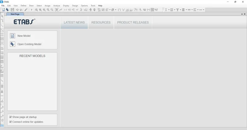
- start the software
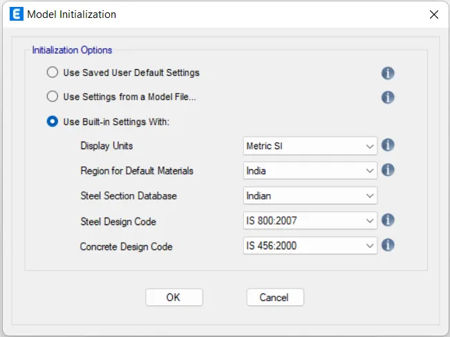
- Select "New Model
- Select "Use the Built-in setting with”
- Now grid and storey settings to be done as per required
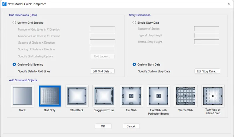
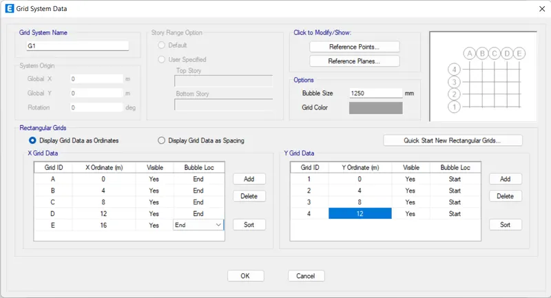
- then click "ok"
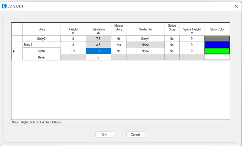
- a new window with the grid and floor will open
- go to: Define
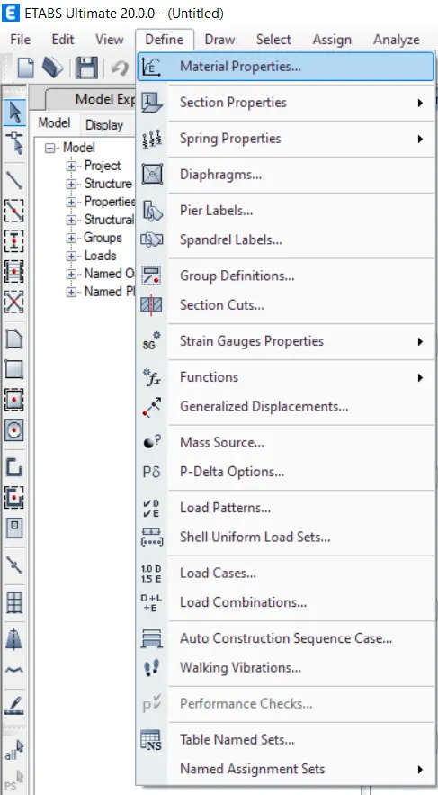
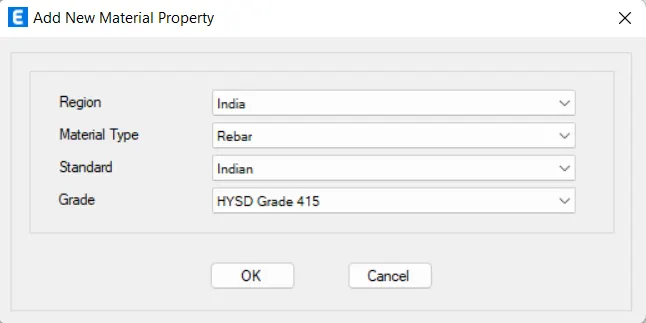
- again, add new material > India >Rebar > Indian > HYSD Grade FE415 > ok
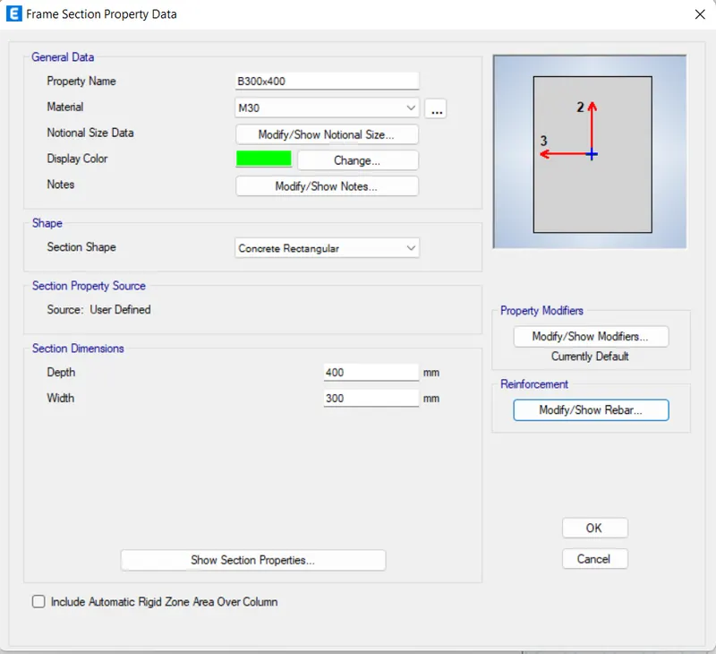
- Go to define tabs section properties > frame section > add new > Column (size) > M30
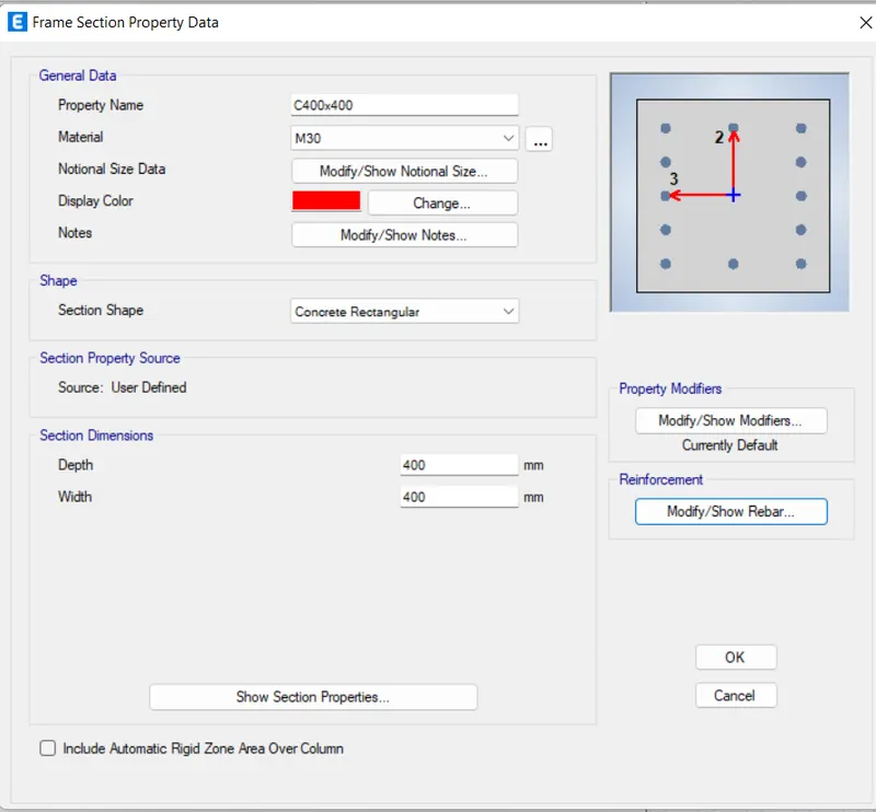
- then again add new Beam (300*400) > M30
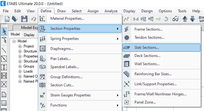
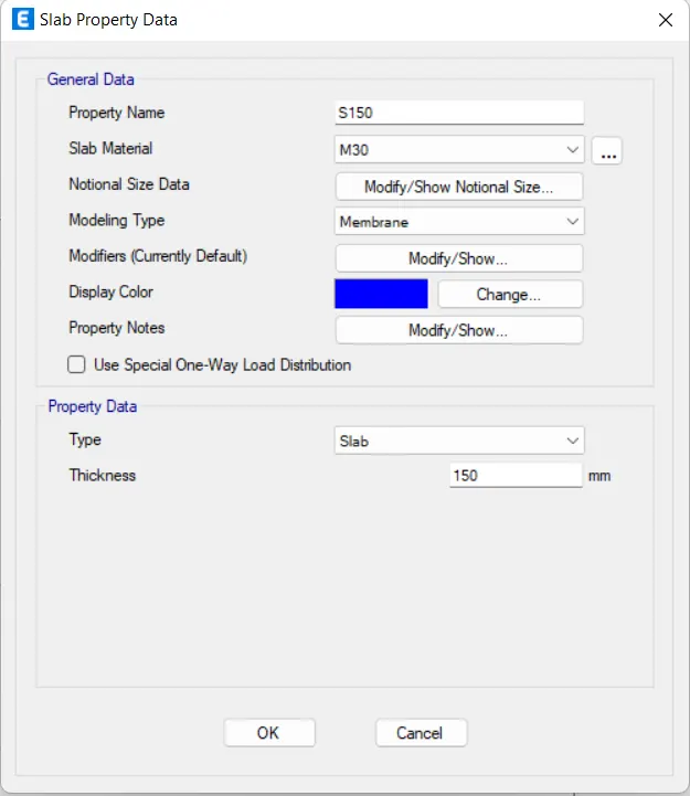
- Go to define tab > section properties > slab section > add new > slab l50 > M30 < thick = 150mm > ok
- Now by using quick draw tools add column, beam, and slab to all the floor as required.
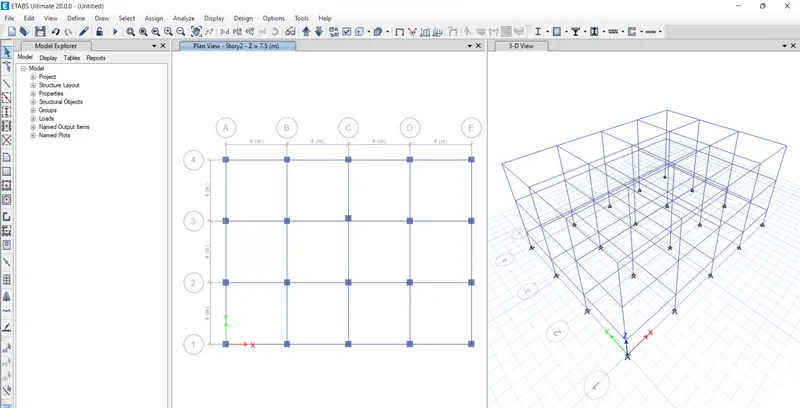
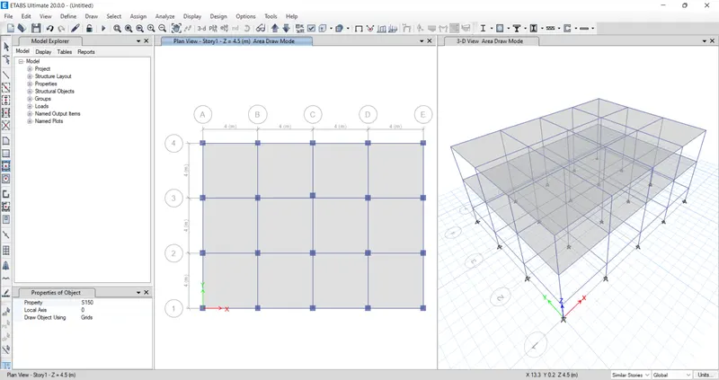
- go to base plan select all the base points.
- Go to Assign menu > Joints > Restraints > pinned > ok
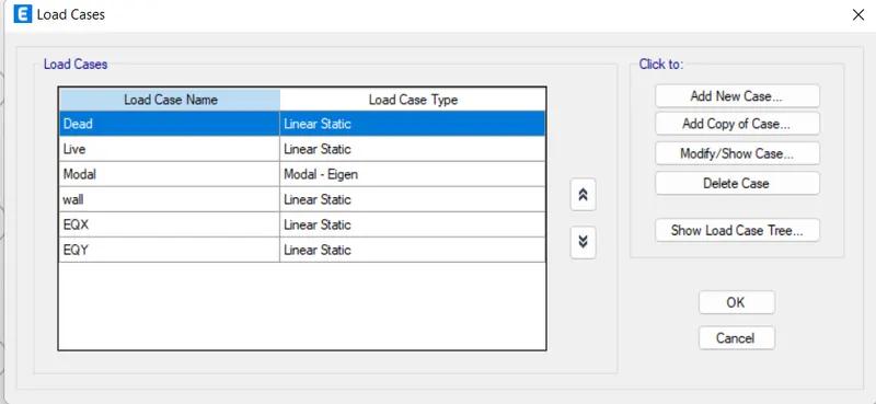
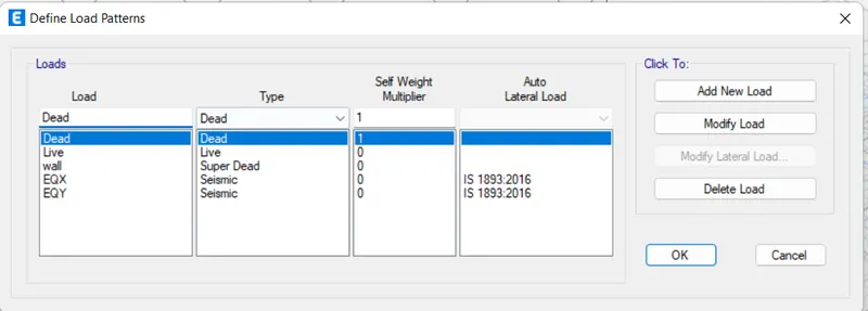
- Go to define tab > Load Pattern > add loads > ok (add all the required load like dead. live, brick wall, etc.)
- Go to define tab > Mass source > modify/show mass sources > specified load patterns > add loads with multiplier values > ok
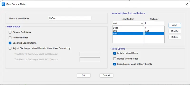
- To add live load and brick wall dead load
- for all other floors except top, go to Assign> shell loads > uniform > lives > 3 kN/m^2 > apply > ok
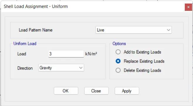
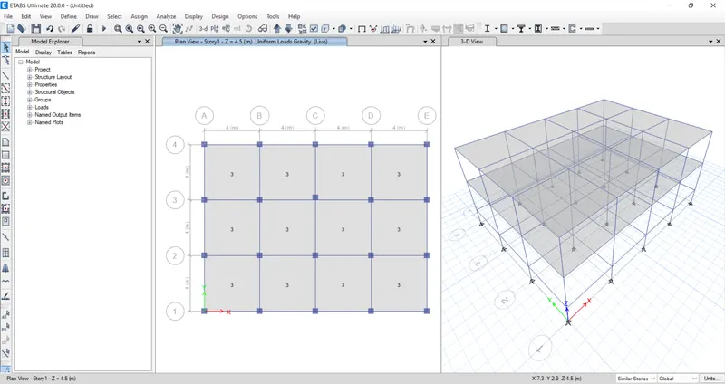
- Now to apply deal load of brick wall go to select tab > object type > beams > ok > close.
- then go to Assign > frame loads distributed > brick wall > 10 kN/m^2 > APPLY > OK
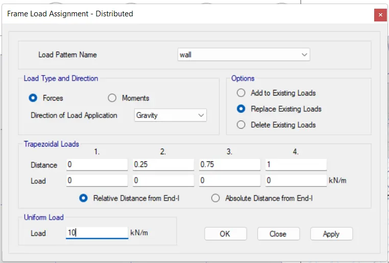
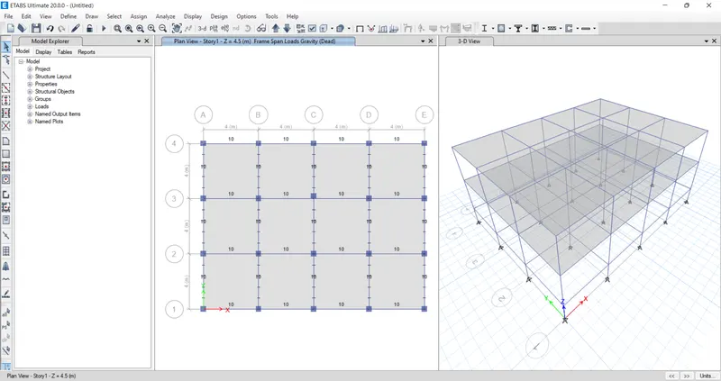
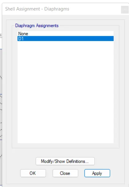
- Then Go to assign > shell > diaphragms D1> Apply > close.
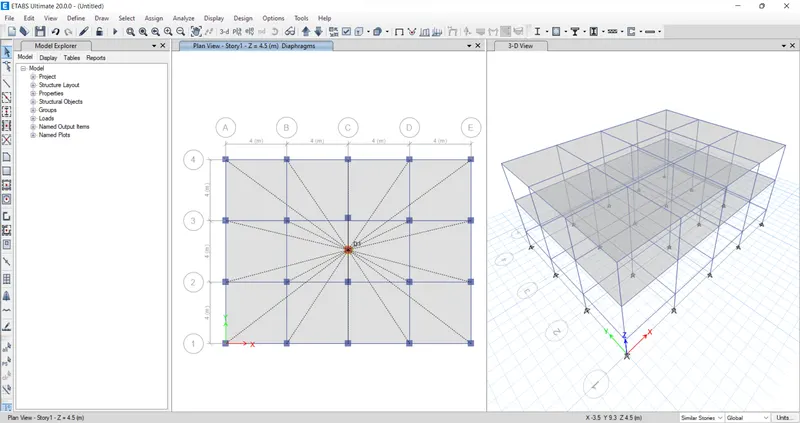
- Now go to analyze > check model > select all > ok
- now you will get a warming tab
- go to analyzes > run analysis
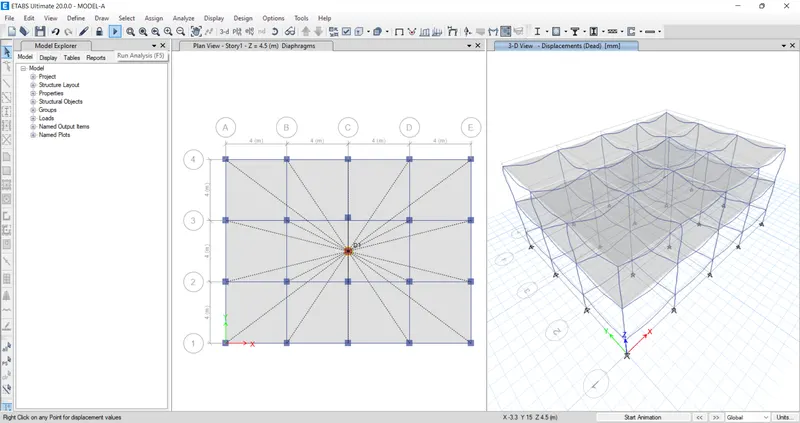
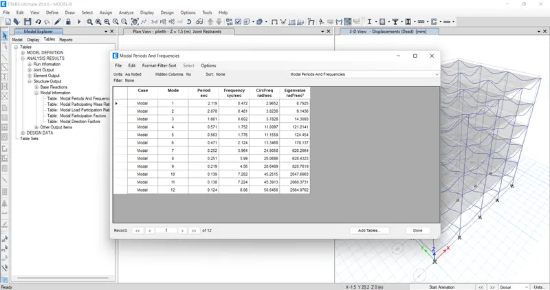
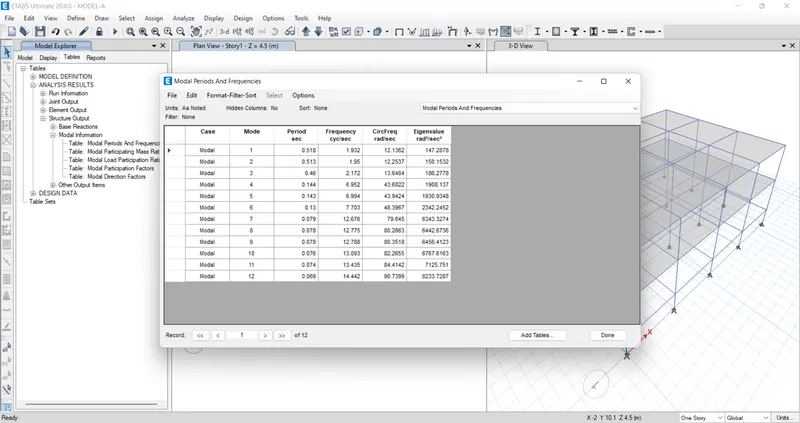
- now to see the results go to: Display > show tables > structure output > model Participation mass ratios (from top right corner drop down menu).
BUILDING: B
- Save the file as model-B, and continue the building B as per question,
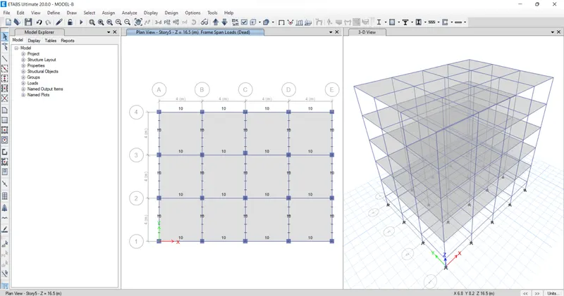
- in building-B, only increasing the storey till storey 5

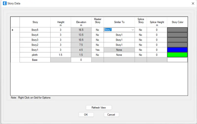
- Edit the number of storeys till G+5, from edit option
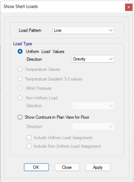
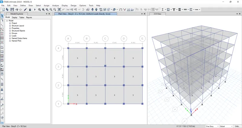
- Assign the sell loads, from previous model to show in model-b
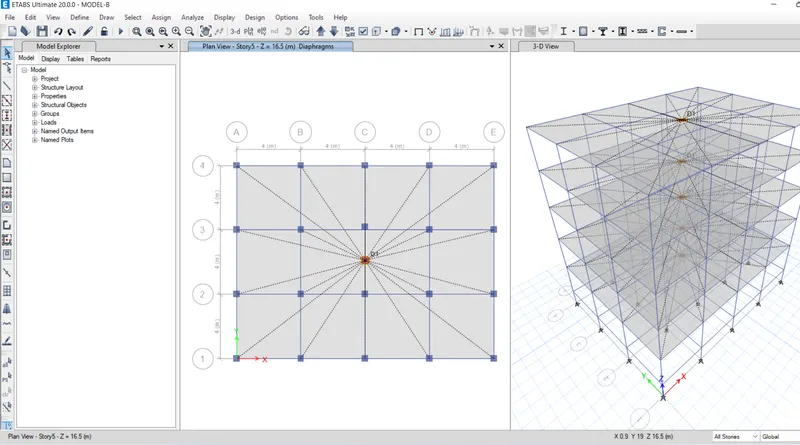
- Now, define the diapragm, by selecting the slab
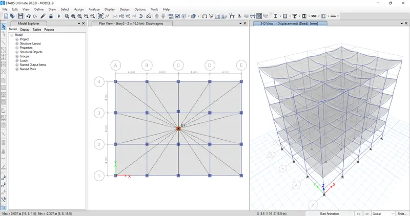
- Run the model, and analyse it
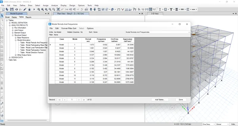
- now to see the results go to: Display > show tables > structure output > model Participation mass ratios (from top right corner drop down menu).
BUILDING: C
- Save the file as model-c, and continue the building b as per question,
- Change the column sizes as (C-550x300) in building-C
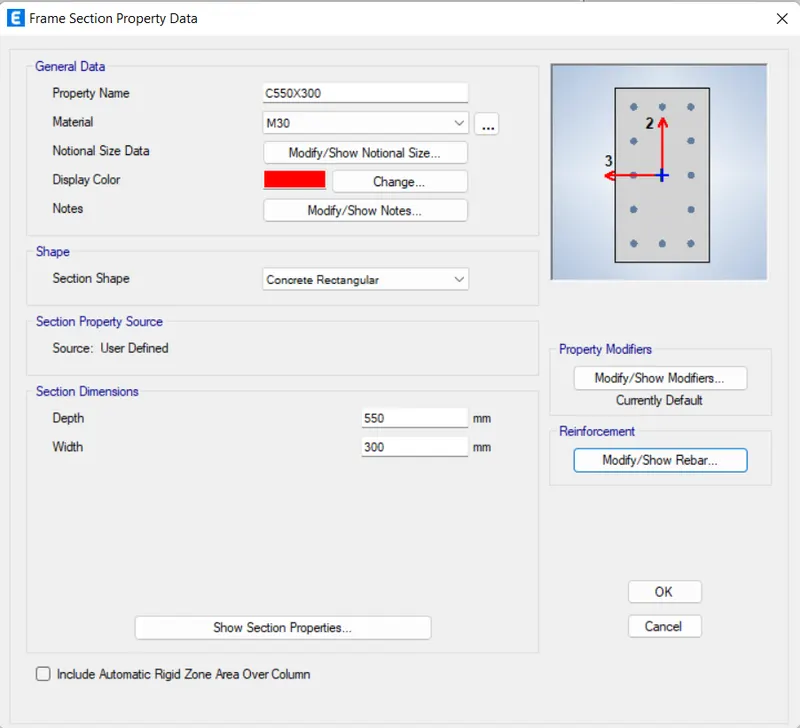
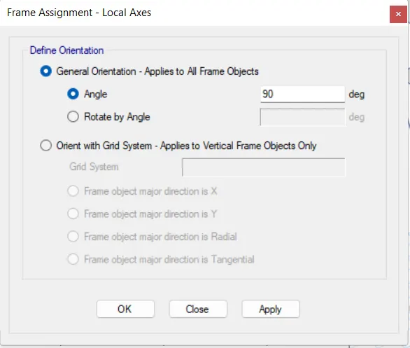
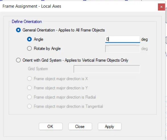
- And rorate the column to 90 degree in the Local axes
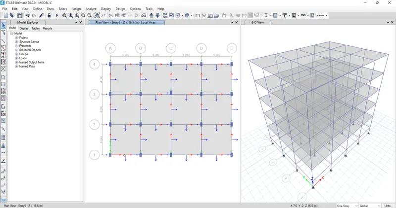
- Now, define the diaphragm, by selecting the slab
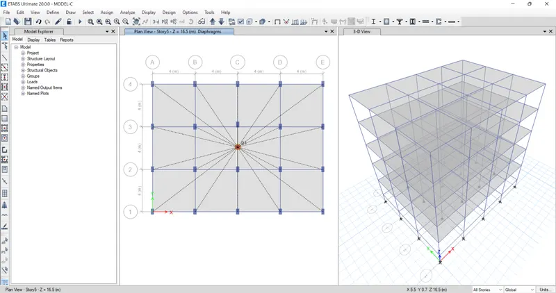
- Run the model, and analyse it
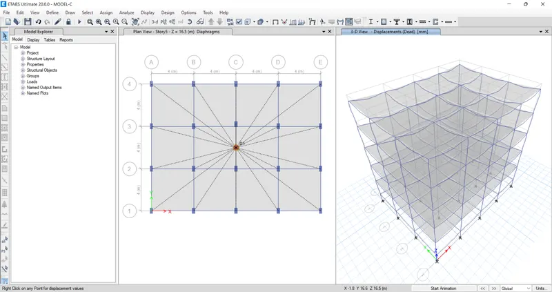
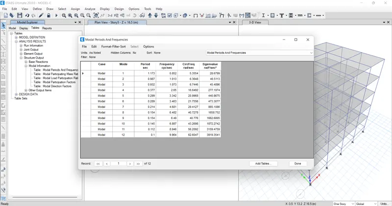
- now to see the results go to: Display > show tables > structure output > model Participation mass ratios (from top right corner drop down menu).
BUILDING: D
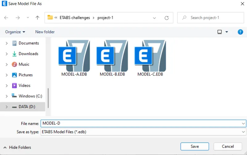
- Save the file as model-D, and continue the building-D as per question,
- And rorate the column to 90 degree in the Local axes
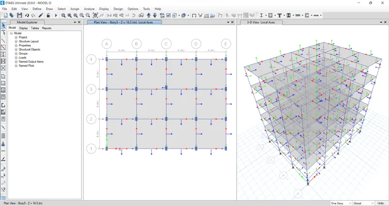
- Now, define the diaphragm, by selecting the slab
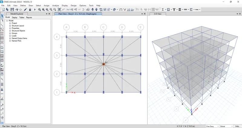
- Run the model, and analyse it
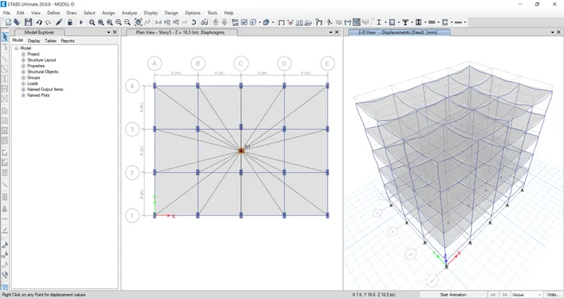
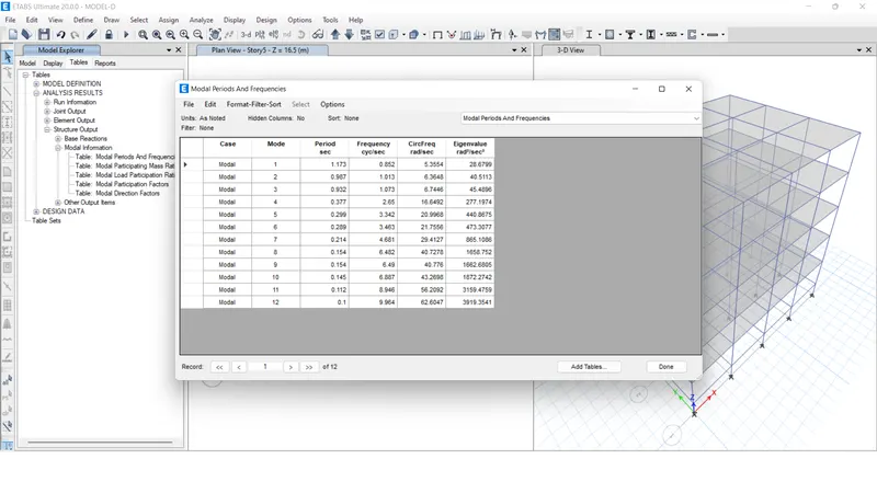
- now to see the results go to: Display > show tables > structure output > model Participation mass ratios (from top right corner drop down menu)
BUILDING: E
- Save the file as model-E, and continue the building E as per question,
- in building-B, only increasing the storey till storey 5
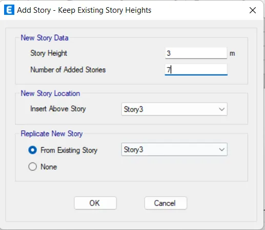
- Edit the number of storeys till G+10, from edit option
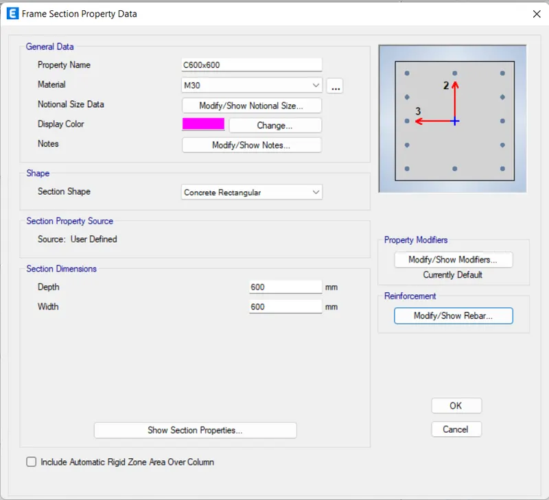
- Change the column sizes as (C-600x600) in building-C
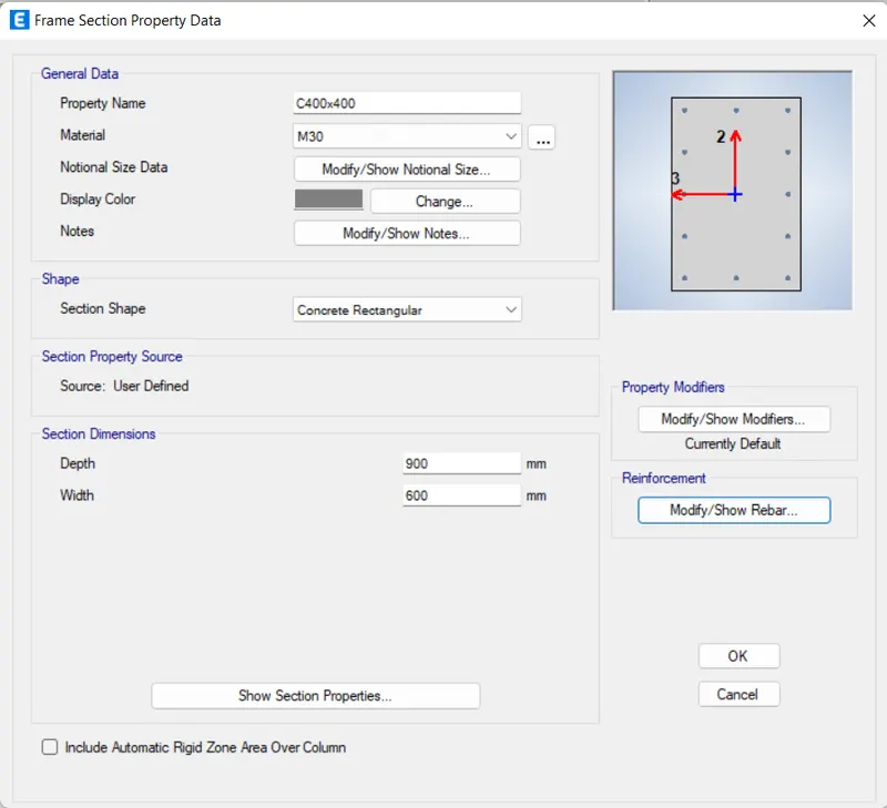
- Change the column sizes as (C-400x400) in building-C
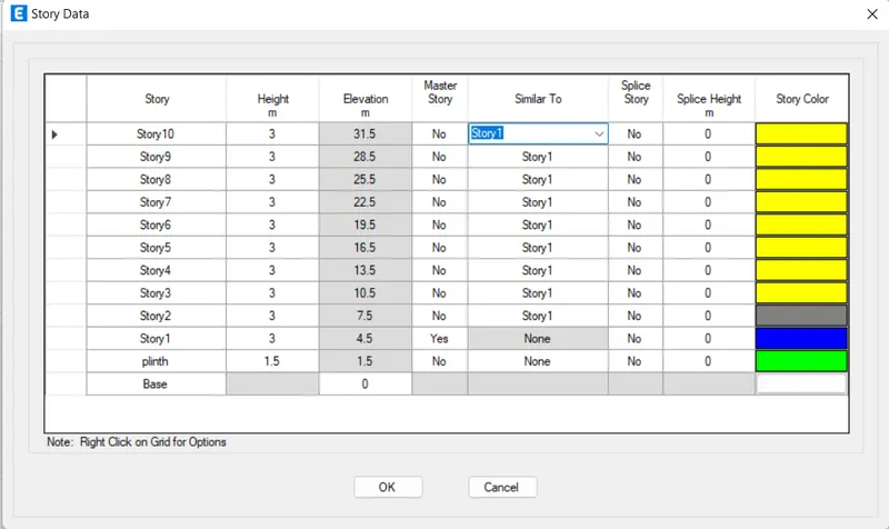
- Assign the different cloumn sizes after storey-6 to storey-10
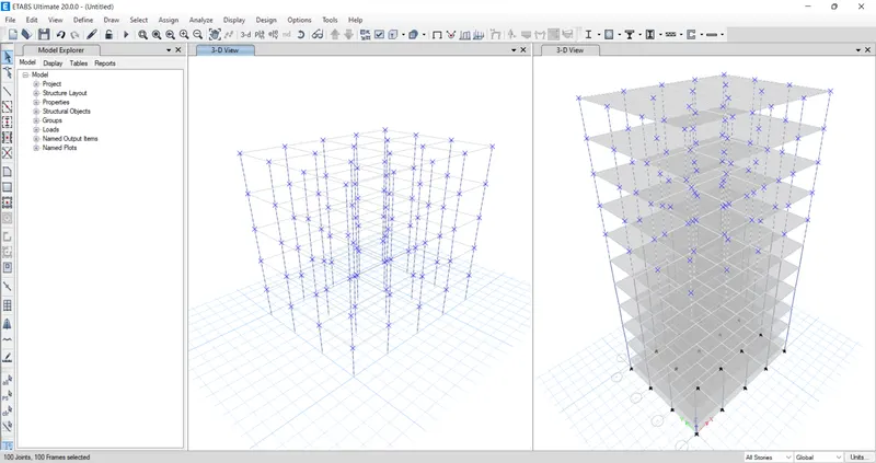
- Now, define the diaphragm, by selecting the slab
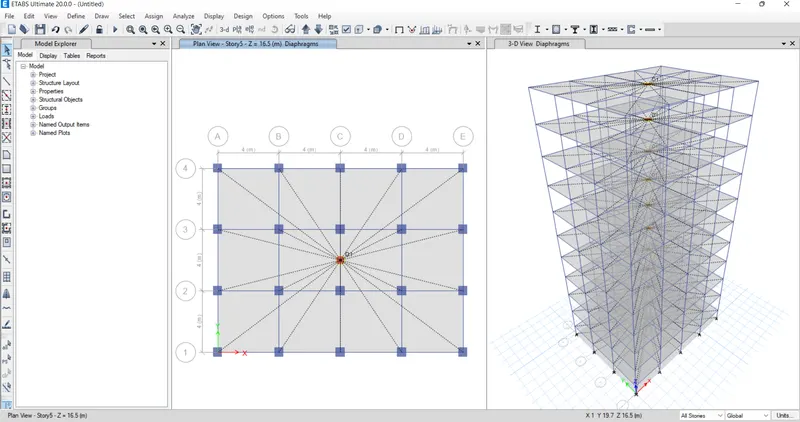
- Run the model, and analyse it
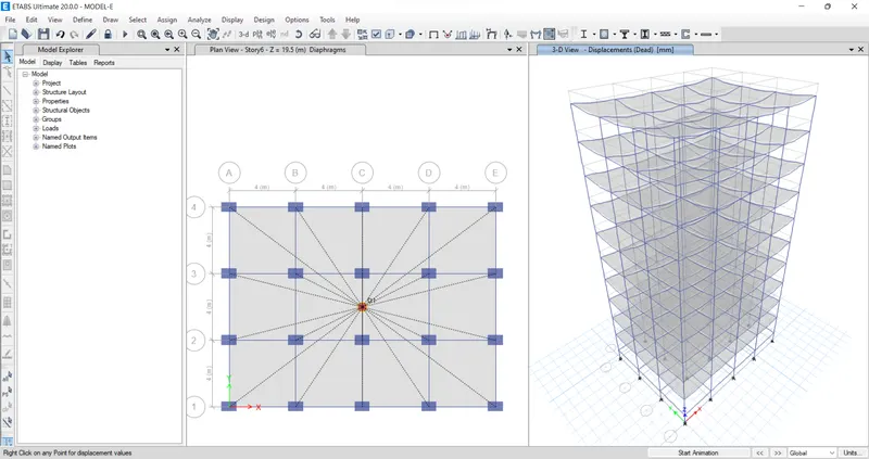
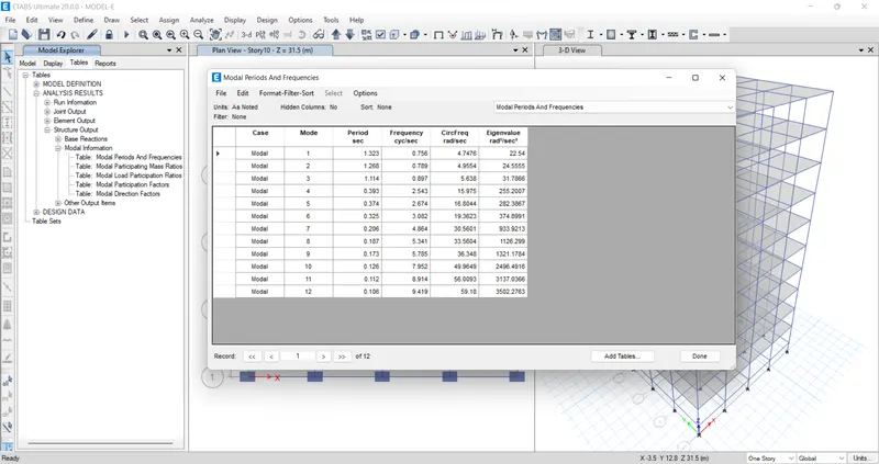
- now to see the results go to: Display > show tables > structure output > model Participation mass ratios (from top right corner drop down menu)
BUILDING: F
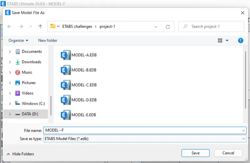
- Save the current file as model-F, and modify the model as per question
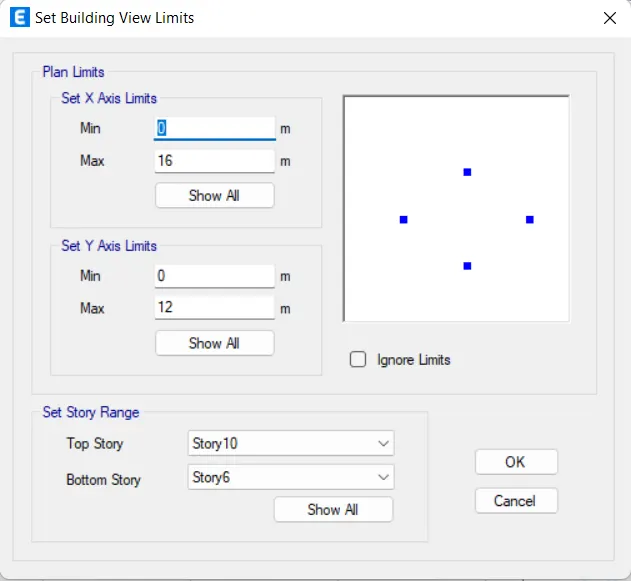
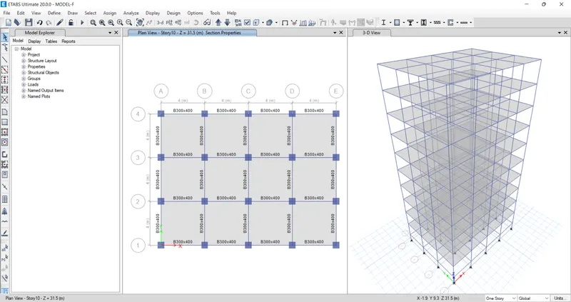
- Change the column of building, from storey-6 to storey-10 by set building view limits, as shown below figure
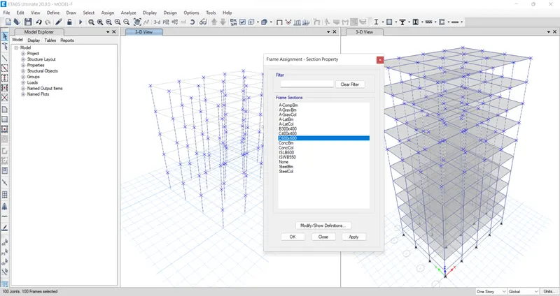
- Define the new column size, as (C600x600) and assign it to selected storey in the building
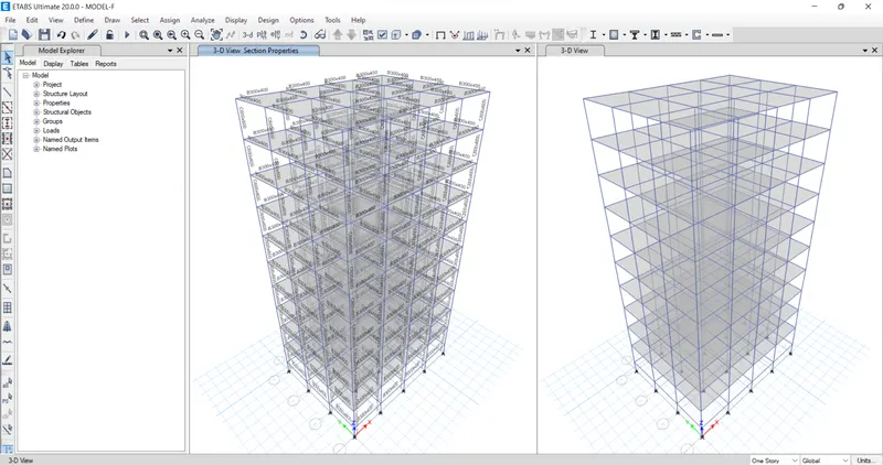
- All column are assign to be C600x600
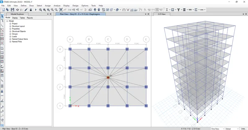
- Now, define the diaphragm, by selecting the slab
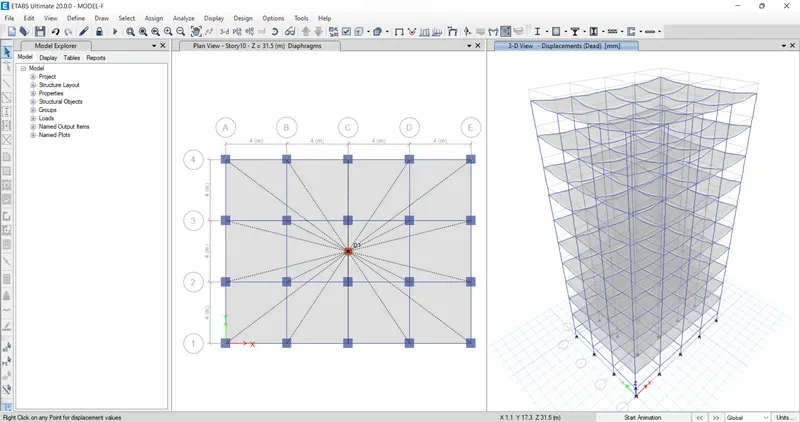
- Run the model, and analyse it
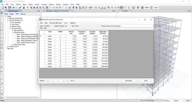
- now to see the results go to: Display > show tables > structure output > model Participation mass ratios (from top right corner drop down menu)
BUILDING: G
- Save the current file as model-G, and modify the model as per question
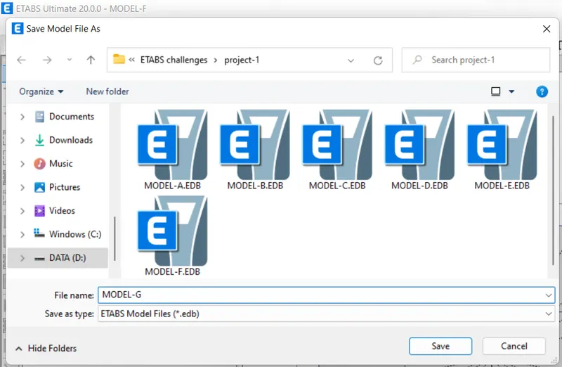
- Edit the storey by edit stories and grid system as per the given question
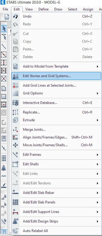
- Increse the number of storey till G+25
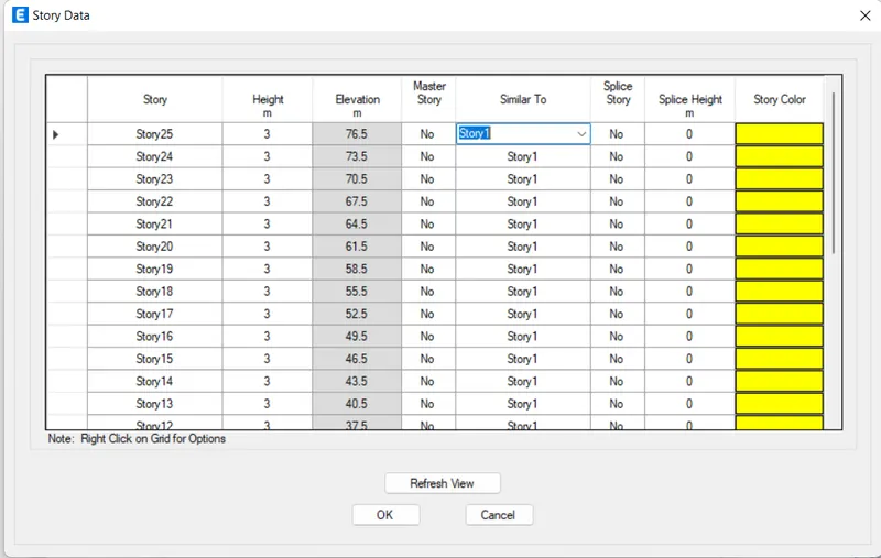
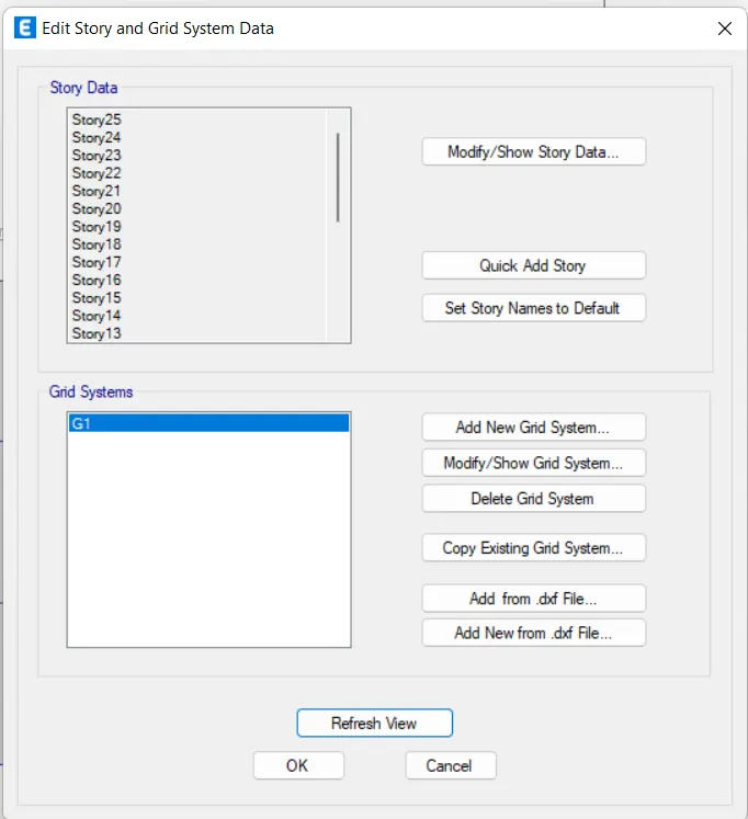
- Assign the sell loads, from previous model to show in model-F
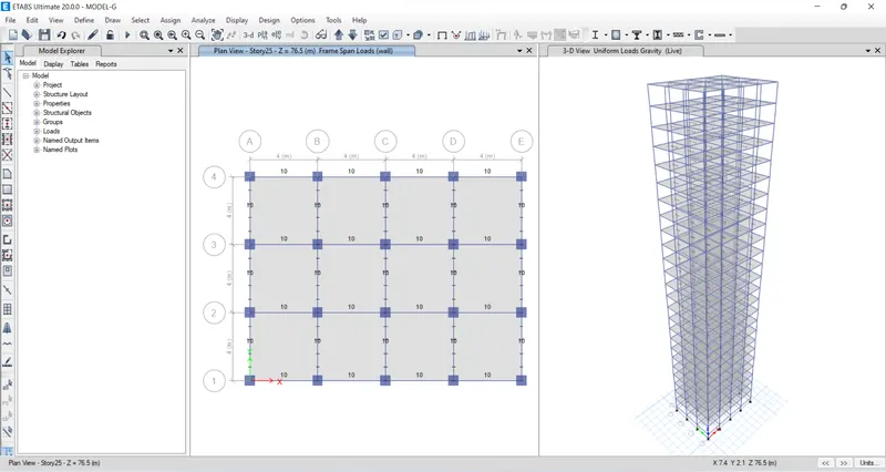
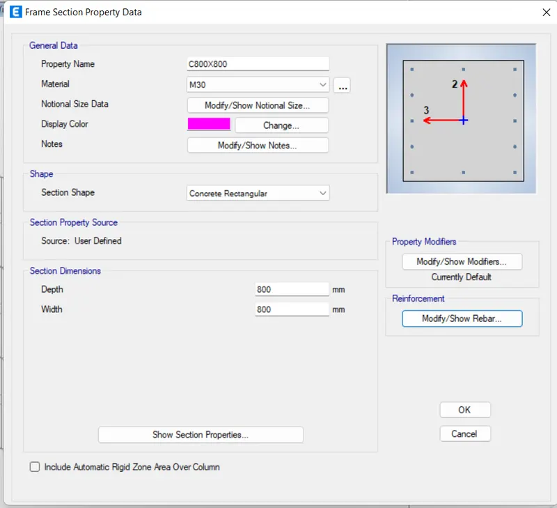
- Define the new column size, as (C800x800) and assign it to selected storey in the building
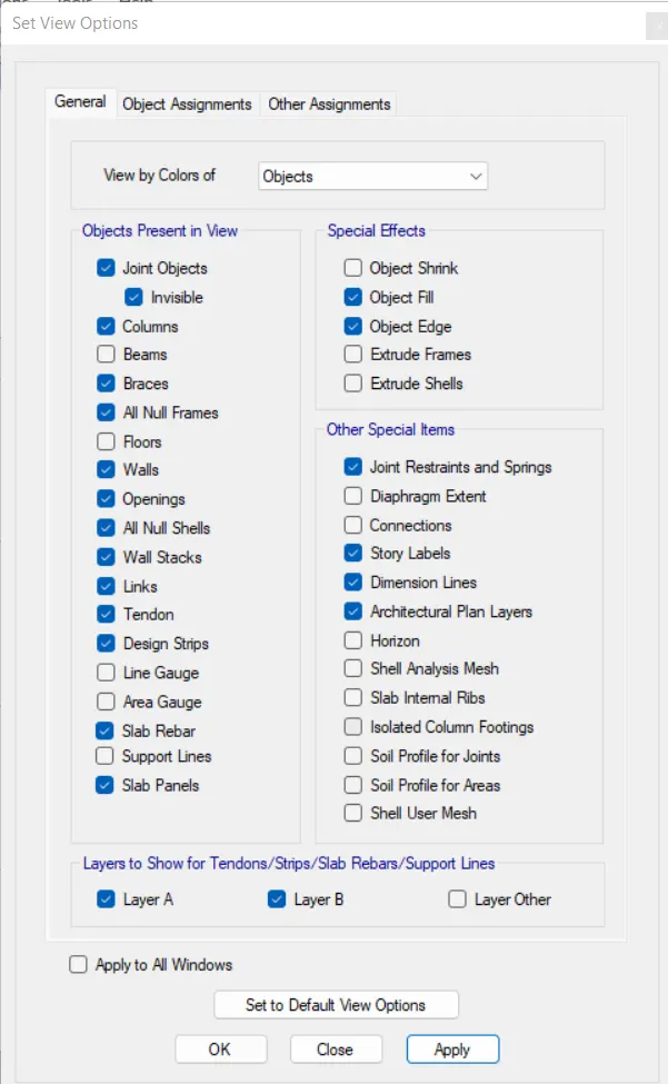
- By set view option deselect the beam and floor to view only the column
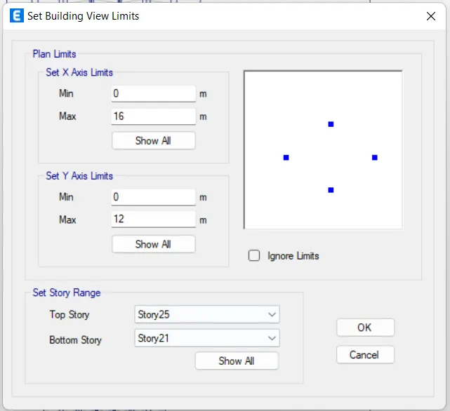
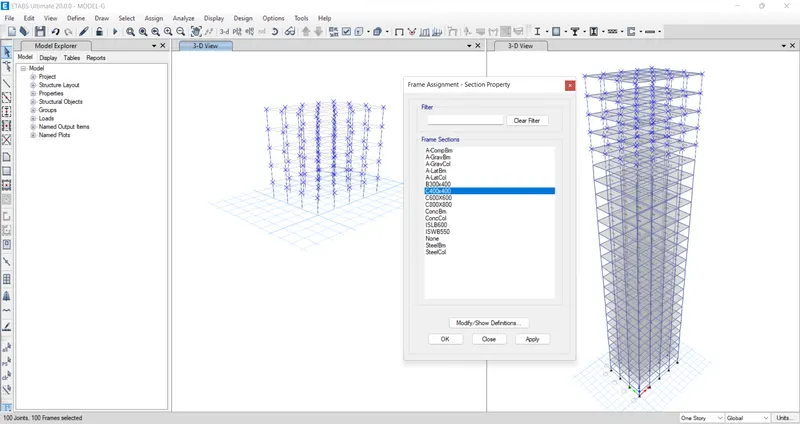
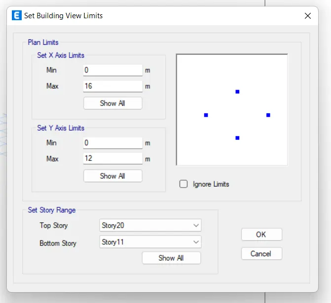
- Change the column of building, from storey-21 to storey-25 by set building view limits, as shown below figure
- Define the new column size, as (C400x400) and assign it to selected storey in the building
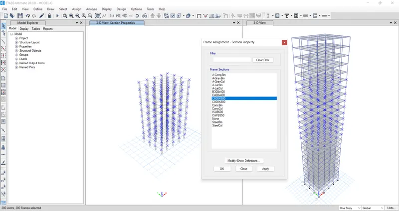
- Change the column of building, from storey-11 to storey-20 by set building view limits, as shown below figure
- Define the new column size, as (C600x600) and assign it to selected storey in the building
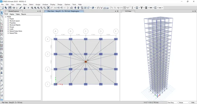
- Now, define the diaphragm, by selecting the slab
- Run the model, and analyse it
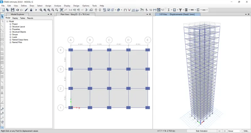
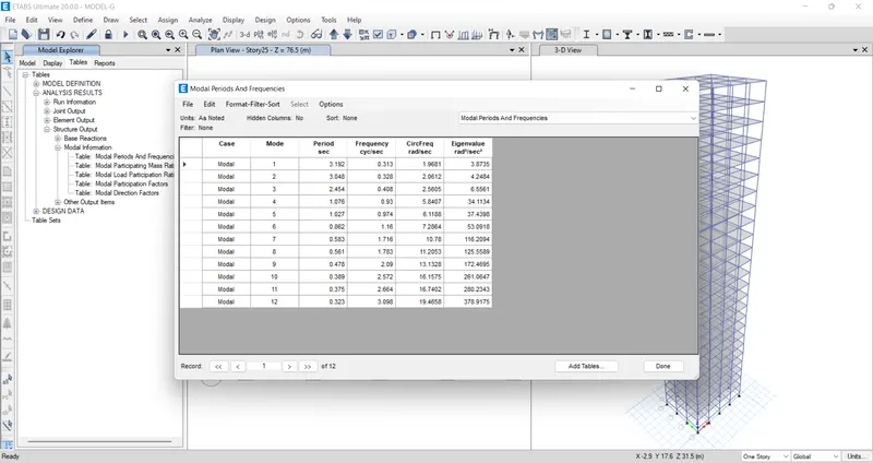
- now to see the results go to: Display > show tables > structure output > model Participation mass ratios (from top right corner drop down menu)
BUILDING: H
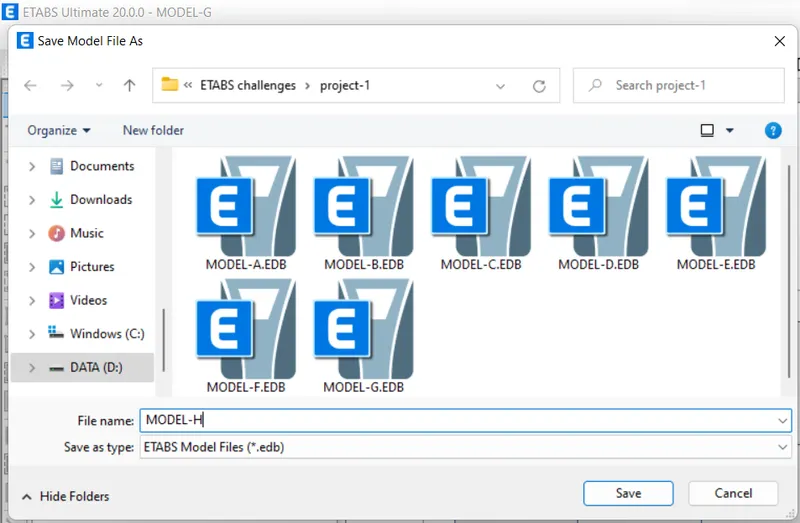
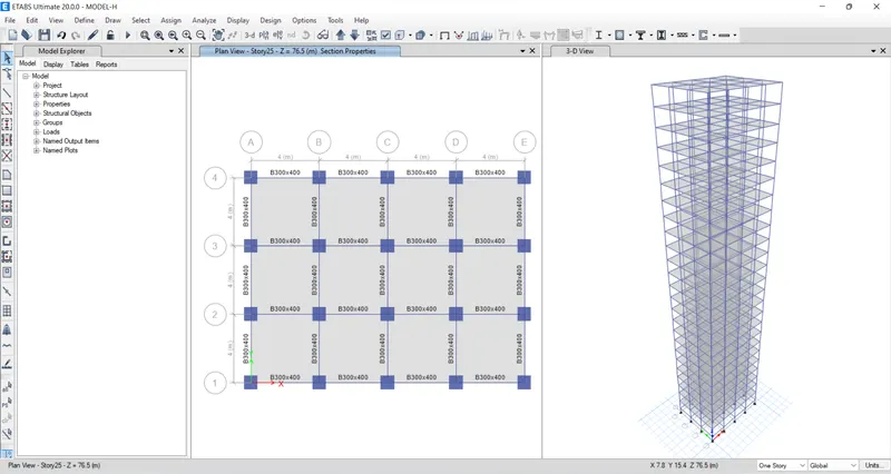
- Save the current file as model-H, and modify the model as per question
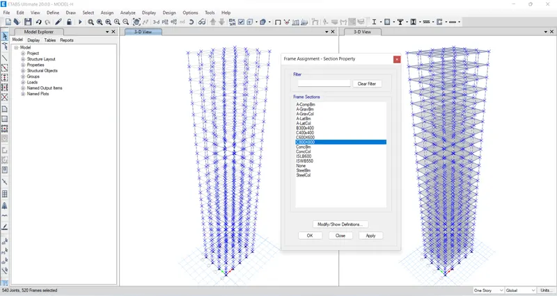
- By set view option deselect the beam and floor to view only the column
- Define the new column size, as (C800x800) and assign it to selected storey in the building
- Now, define the diaphragm, by selecting the slab
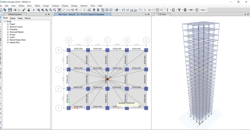
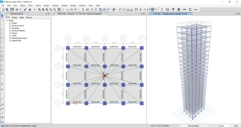
- Run the model, and analyse it
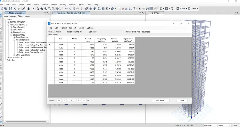
- now to see the results go to: Display > show tables > structure output > model Participation mass ratios (from top right corner drop down menu)
BUILDING: J
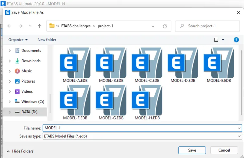
- Save the current file as model-j, and modify the model as per question
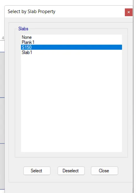
- Select the slab from select by slab property
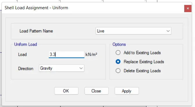
- Change the shell load to 3.3kN/m^2
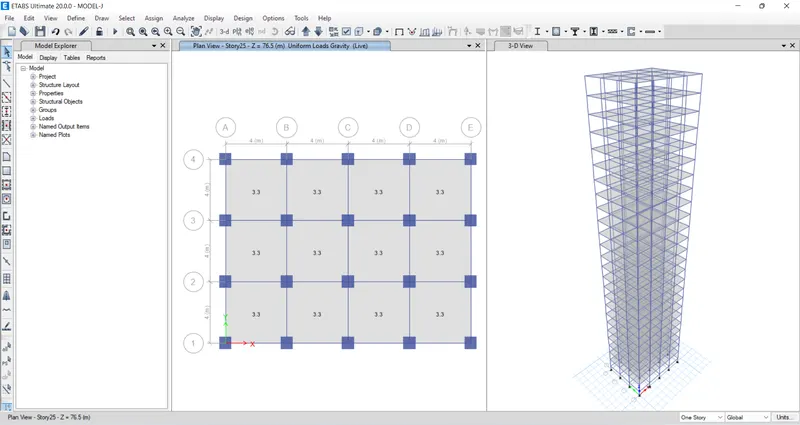
- All loads is replace from 3kN/m^2 to 3.3kN/m^2 as shown below figure
- Now, define the diaphragm, by selecting the slab
- Run the model, and analyse it
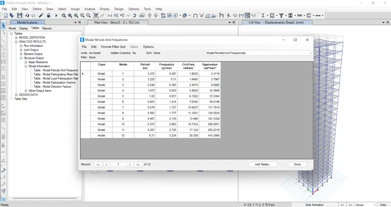
- now to see the results go to: Display > show tables > structure output > model Participation mass ratios (from top right corner drop down menu)
BUILDING: K
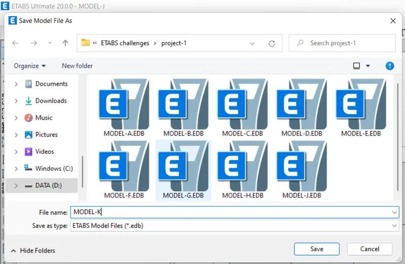
- Save the current file as model-k, and modify the model as per question
- Select the sell load, and assign the new loads to 3.6kN/m^2 as 20% increse in the load
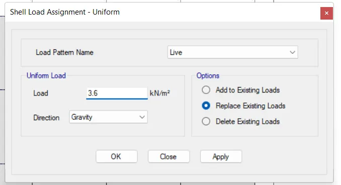
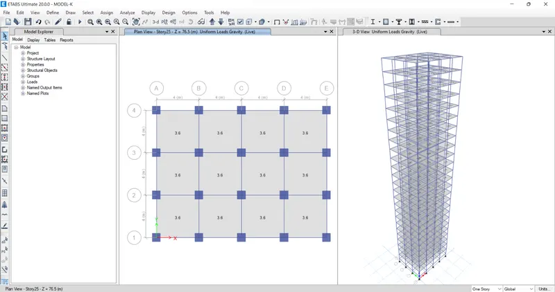
- All loads is replace from 3.3kN/m^2 to 3.6kN/m^2 as shown below figure
- Now, define the diaphragm, by selecting the slab
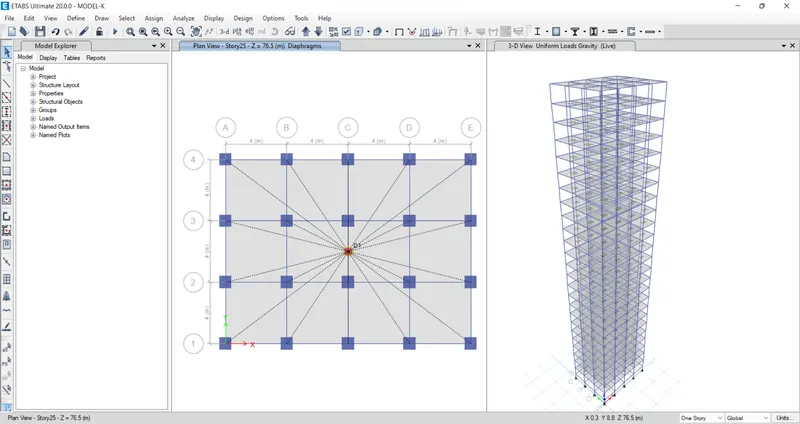
- Run the model, and analyse it
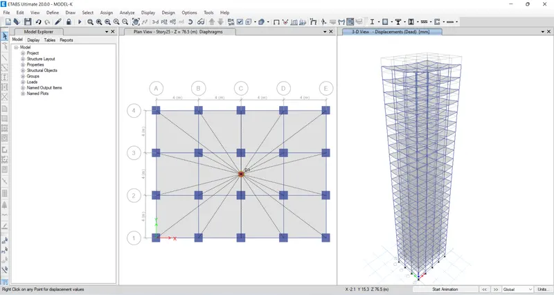
- now to see the results go to: Display > show tables > structure output > model Participation mass ratios (from top right corner drop down menu)
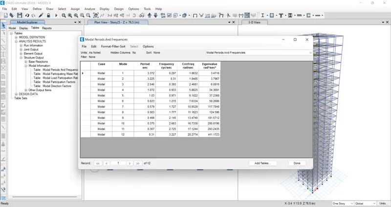
RESULTS
Extra loads to be increse in building:
BUILDING: J
- In this case we need to add imposed load 10% more than that in "building case J".
- imposed load in other way is said to be Live load, so the live load added in previous building was 3 KN/m2
- Hence, the 10% live load in this case is added to be 3.3 kN/m^2
BUILDING: K
- In this case we need to add imposed load 20% more than that in "building case J".
- imposed load in other way is said to be Live load, so the live load added in previous building was 3 kN/m^2
- Hence, the 20% live load in this case is added to be 3.6 kN/m^2
COMPAIRING RESULTS ON THE BASIS OF GIVEN TASK
1. Effect of stiffness on T: Compare fundamental natural periods of buildings E &F as well as G & H. Why is there a marginal or significant difference in the fundamental natural periods?
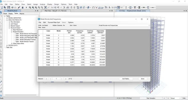
- The fundamental Natural period of building E is 1.323 sec
- The fundamental Natural period of building F is 1.256 sec
- The fundamental Natural period of building G is 3.192 sec
- The fundamental Natural period of building H is 3.372 sec
Reason:
- On comparing E and F, the significant changes in the time period is caused because we used Two different type of column sizes in Building E and only One type of column in F building.
- on comparing G and H. The significant changes in the time period are caused because we used three different type of column sizes In Building & and only one type of column in H building.
2. Effect of mass on T: Compare fundamental natural periods of buildings H, J and K. Have the buildings become more flexible or stiff due to change in mass?
- The fundamental Natural period of building H is 3.372 sec
- The fundamental Natural period of building J is 3.372 sec
- The fundamental Natural period of building K is 3.372 sec
Reason:
- On comparing the fundamental natural periods of buildings H, J and K we can see a no change in time period of H comparing to J and K, as well as the time period is constant in J and K. these small changes happened because of bit increment in live load.
- From this we can say that, as the stiffness, mass, storeys of building increases natural period increases.
- Also the weight of building is directly proportional to the flexibility of the structure.
3. Effect of Building Height on T: How does the fundamental natural periods of Buildings A, B, F and H change with change in building height?
- The fundamental Natural period of building A is 0.518 sec
- The fundamental Natural period of building B is 1.073 sec
- The fundamental Natural period of building F is 1.256 sec
- The fundamental Natural period of building H is 3.372 sec
Reason:
- On comparing A, B, F. & H: we can say that as the height of the building gets increased, the time period of the building also increases.
- so, time period is directly proportional to Height of building
4. Effect of Column Orientation on T: How does the fundamental natural periods of Buildings B, C and D change with change in column orientation?
- The fundamental Natural period of building B is 0.518 sec
- The fundamental Natural period of building C is 1.173 sec
- The fundamental Natural period of building D is 1.173 sec
Reason:
- On comparing B, C, & D: we can see that the time period of C is equal to D which Intern is more than B
- So, the stiffness of building is more if the columns are oriented in longer length direction.
5. Effect of Flexural Stiffness of Structural Elements on mode shapes: Compare fundamental mode shape of Building B in two situations when flexural stiffness of beams relative to that of adjoining columns is very small versus when it is large.
- On Comparing fundamental mode shape of Building B in two situations when flexural stiffness of beams relative to that of adjoining columns is very small versus when it is large.
- For situation when flexural stiffness of beams is smaller than adjoining column:
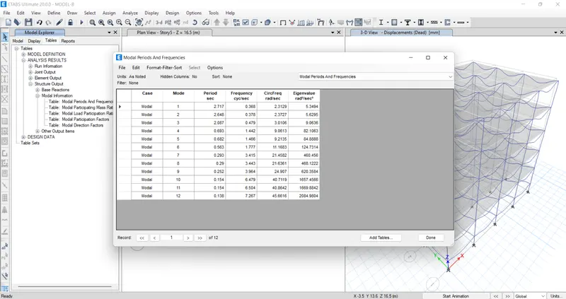
6. Effect of Axial Stiffness of Vertical Members on mode shapes: Compare fundamental mode shape of Building H in two situations when axial cross-sectional area of columns is very small versus when it is large.
- On Comparing fundamental mode shape of Building H in two situations when axial cross-sectional area of columns is very small versus when it is large.
- For situation when axial cross-sectional area of columns is very small
7. Effect of Degree of Fixity at column bases on mode shape: Compare fundamental mode shape of Building B in two situations when base of columns is pinned versus when it is fixed.
- On Comparing fundamental mode shape of Building B in two situations when base of columns is pinned versus when it is fixed.
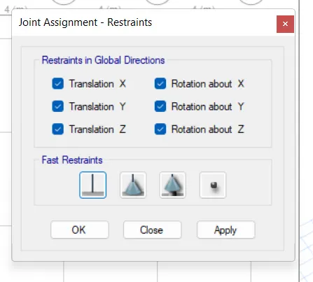
- For situation when base of column is pinned