Project 1_Comparative study of different storey buildings for Seismic forces
Project :- 1
Comparative study of different storey buildings for Seismic forces
Aim :-
- The model and analyse multiple building with different floor levels and design parameters using ETabs software and compare the results to understand their overall siesmic behaviour.
Introduction :-
Etabs :-
- ETABS is one of the most powerful software tools for structural analysis.
- 3D modeling, visualization, and automatic code-based learning are some of the unique features of this software.
- ETABS also supports several analytical models like response spectrum analysis, time-history analysis, and line direct integration time-history analysis.
Advantages :-
- Built-in drawing utilities: To aid the engineers in modeling, ETABS comes with a built-in feature for drawing and drafting. Some other packages also have this feature, but the quality is much better in ETABS.
- Extensive reports: ETABS generates detailed and comprehensive reports for every project or task you perform, be it calculation of stresses, deformation or failure analysis, and design summary.
- Design of concrete and steel frames: Among all the materials available to build structures, concrete and steel are by far utilized the most in terms of volume. ETABS has specialized modules that deal with concrete and steel frames to optimize your calculations and offer capacity checks for frame elements.
Factors influencing the dynamic characteristics of a building :-
- Buildings oscillate during earthquake shaking. The oscillation causes inertia force to be induced in the building.
- The intensity and duration of oscillation, and the amount of inertia force induced in a building depend on features of buildings, called their dynamic characteristics, in addition to the characteristics of the earthquake shaking (beyond the control of an engineer) itself.
- The important dynamic characteristics of buildings are modes of oscillation and damping (assumed constant in most practical cases). A mode of oscillation of a building is defined by associated Natural Period and Deformed Shape in which it oscillates.
- Every building has a number of natural frequencies (how many?), at which it offers minimum resistance to shaking induced by external effects (like earthquakes and wind) and internal effects (like motors fixed on it).
- Each of these natural frequencies and the associated deformation shape of a building constitute a Natural Mode of Oscillation.
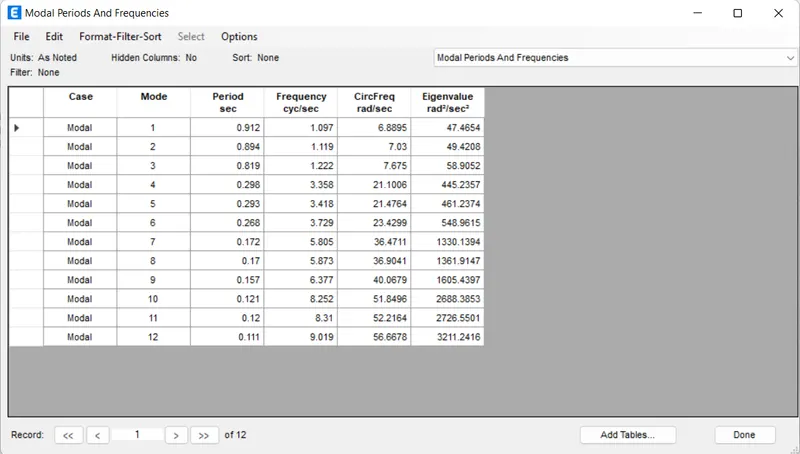
- The mode of oscillation with the smallest natural frequency (and largest natural period) is called the Fundamental Mode; the associated natural period T1 is called the Fundamental Natural Period.
- Regular buildings held at their base from translation in the three directions, have two fundamental translational natural periods, Tx1 and Ty1, associated with its horizontal translational oscillation along X and Y directions, respectively, and one fundamental rotational natural period Tθ1 associated with its rotation about an axis parallel to Z axis.
Procedure :-
1.Builging A (G+2)
- Open the ETabs software.
- Click the file menu and choose to create a new model option.
- After choosing a new model a dialogue box will appear as Model Initialization.
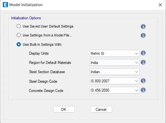
- Choose the built-in settings option and select the display units and codes.
- New dialogue box will appear named New Model Quick Templates.
- Select Custom Grid spacing and custom story data.
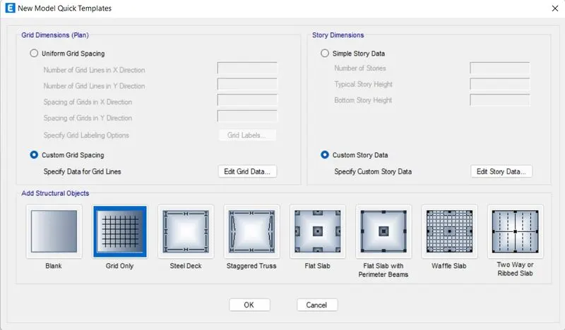
- After models initialization, select grid and storey inputs from new model quick templates dialogue box.
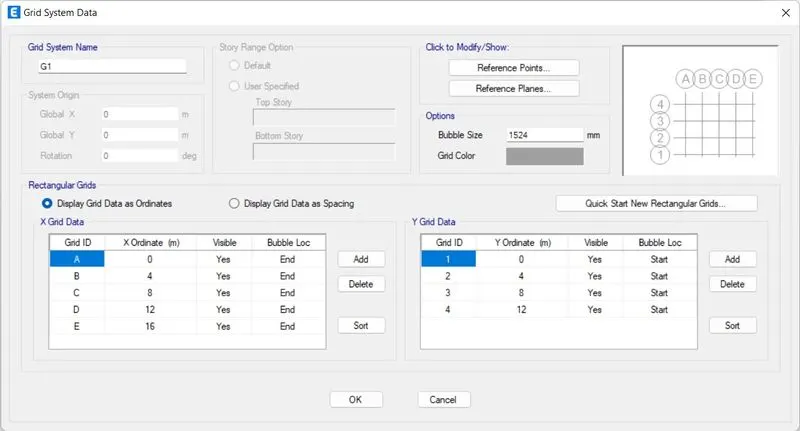
- In the dialogue box choose grid spacing and custom story data which is used to provide the input specified above.
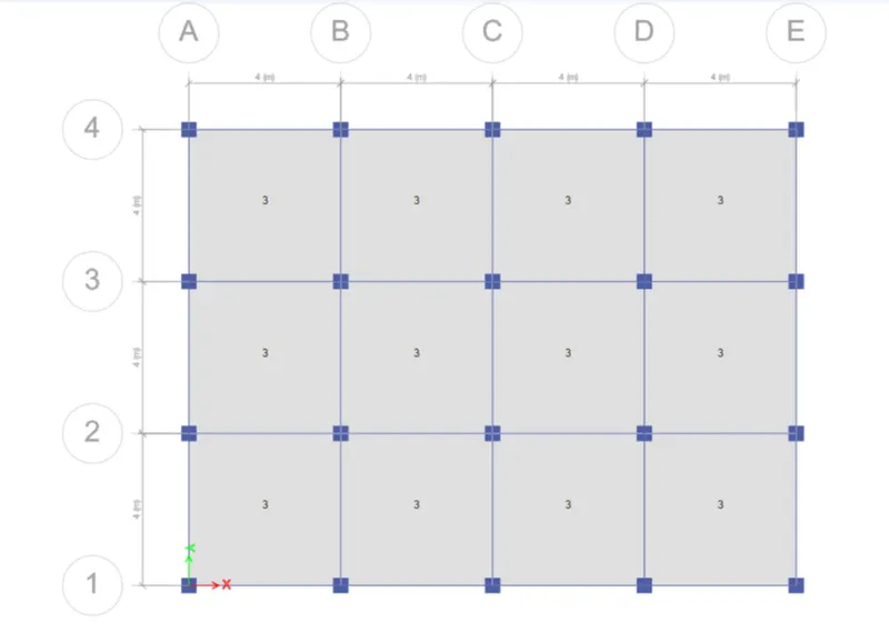
- Enter X Grid data at a distance of 4 m and Y Grid data as 4 at a distance of 4m.
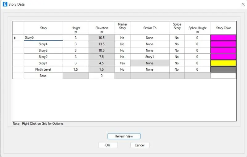
- Now edit stories by using the user-defined story input, 2 stories are incorporated (plinth at 1.5m and 2 story with 3m height each).
- Storey 1 has been labelled as a master storey and all above levels are labelled similar to that.
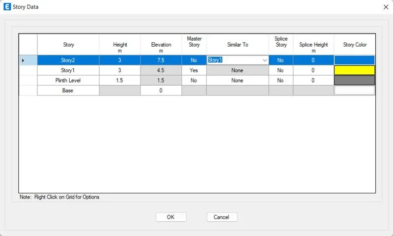
- So, 2 storeys are successfully added in the peoject.
- Create alll the storeys as similar to storey 1.
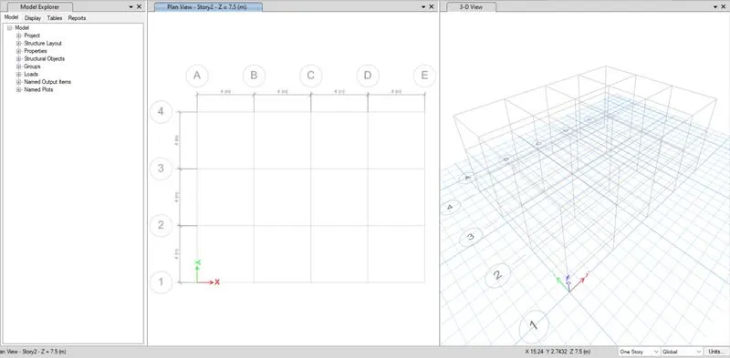
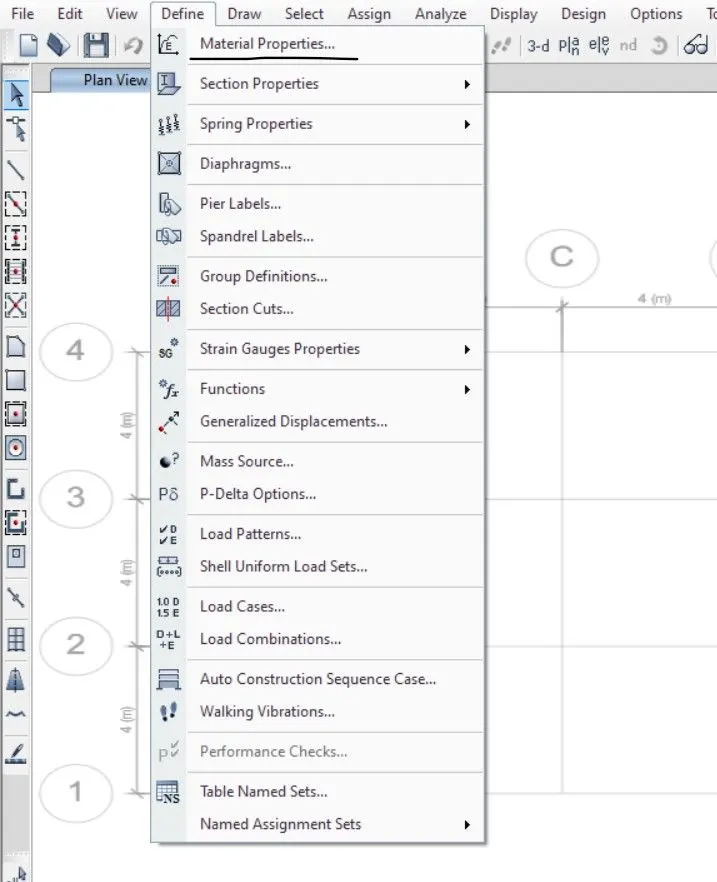
- Select Material properties under define tab.
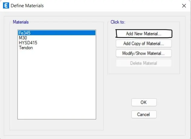
- New dialogue box will appear named Define Materials.
- Select Add new Material from the window.
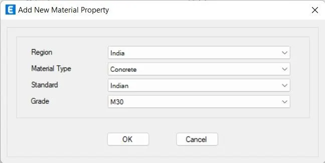
- Define the materials of concrete M30 Grade and steel of reinforcement as 415 Grade and longitudinal reinforcement as 500 Grade.
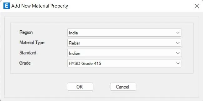
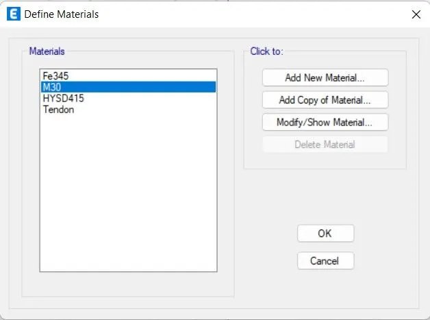
- Now select Section Properties under Define Tab.
- Select Frame Sections.
- Select Add new properties in Frame Properties.
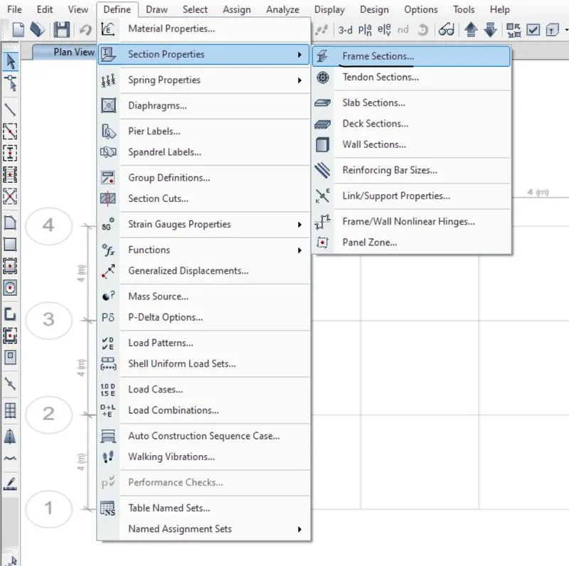
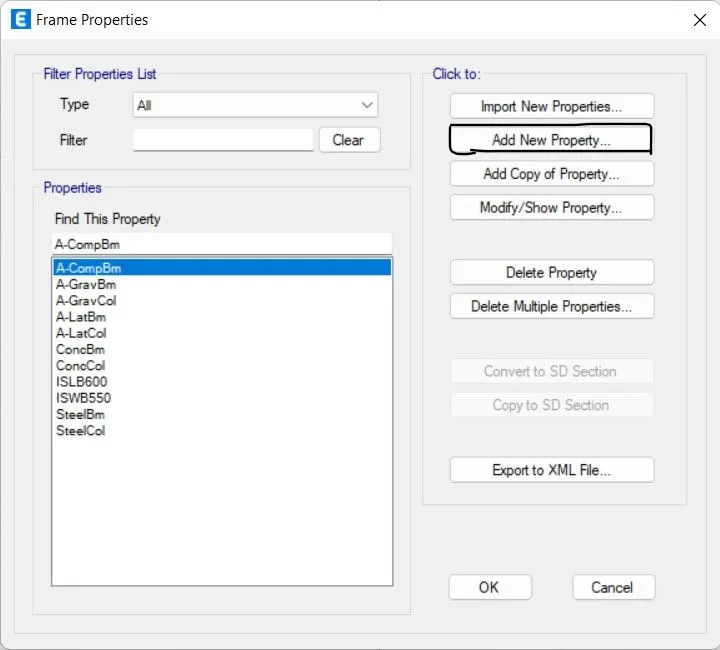
- Create a new Property as a beam and input values as 300X400.
- Select Modify/Show Rebar in Reinforcement option.
- Select M3 Design only (Beam).
- Select Reabar as HYSD415.
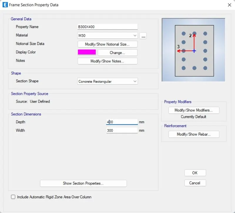
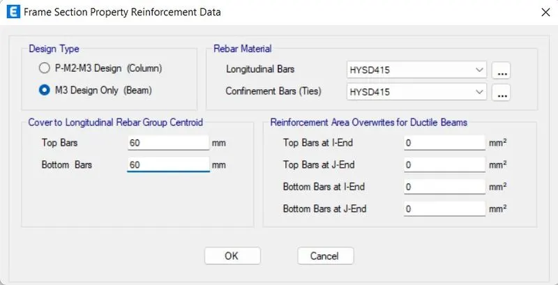
- Create a new Property as a column and input values as 400X400.
- Select Modify/Show Rebar in Reinforcement option.
- Select P-M2-M3 Design (Column).
- Select Reabar as HYSD415.
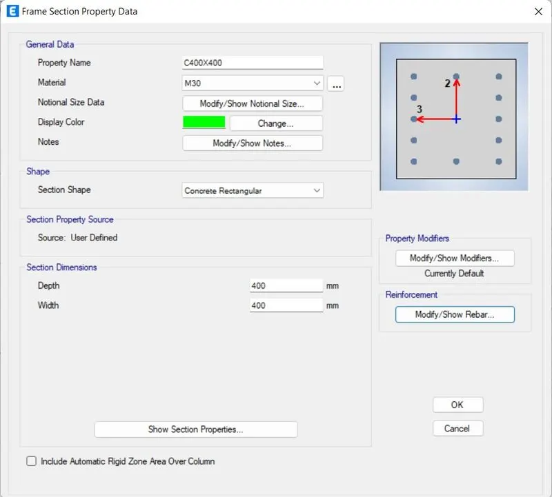
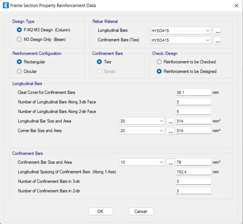
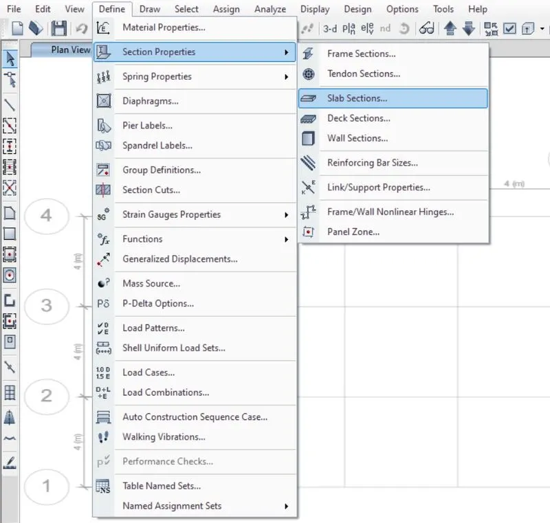
- Now select Section Properties under Define Tab.
- Select Slab Sections.
- Select Add new properties in Slab Properties.
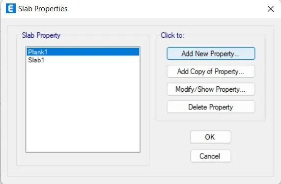
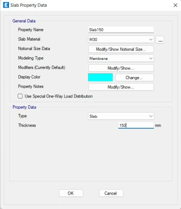
- Using the membrane properties, slab size 150 mm has been added to the list.
- Membrane property will help to consider only slab weights and Floor weights in analysis of structure while no stiffness component of flange advantage are considered during calculation.
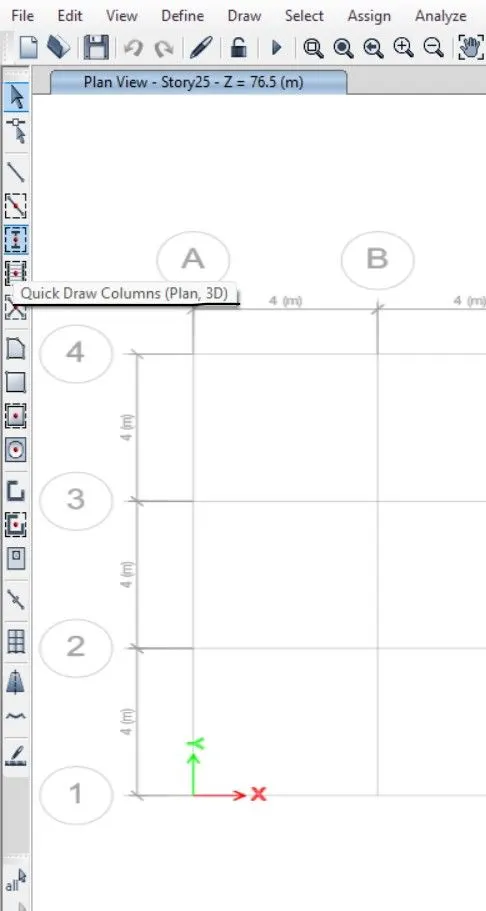
- Now draw columns of size 400X400mm at the intersection of the horizontal and vertical grids and beams with quick draw Column keeping all the stories on.
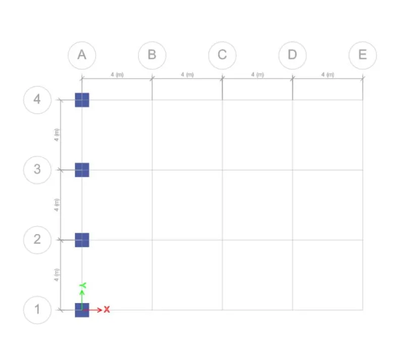
- Now Go to Replicate tool in Edit Menu.
- In Linear Option, Select dx as 4 and dy as 0.
- inser the Number as 4.
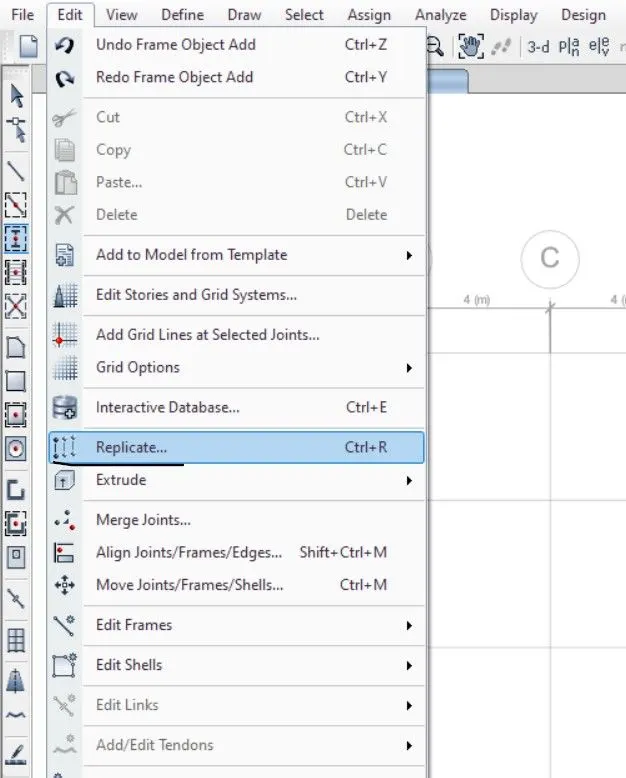
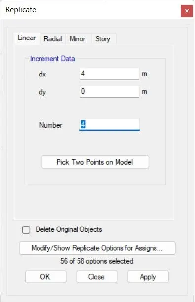
- Columns are Successfully added to the structure.
- Now draw the Beams.
- Draw beams of size 300X400mm at the intersection of the horizontal and vertical grids and beams with quick draw beam keeping all the stories on.

- Beams are Successfully added to the structure.
- Now select the PLAN option from menu bar.
- Select Story 1 in Plan View.
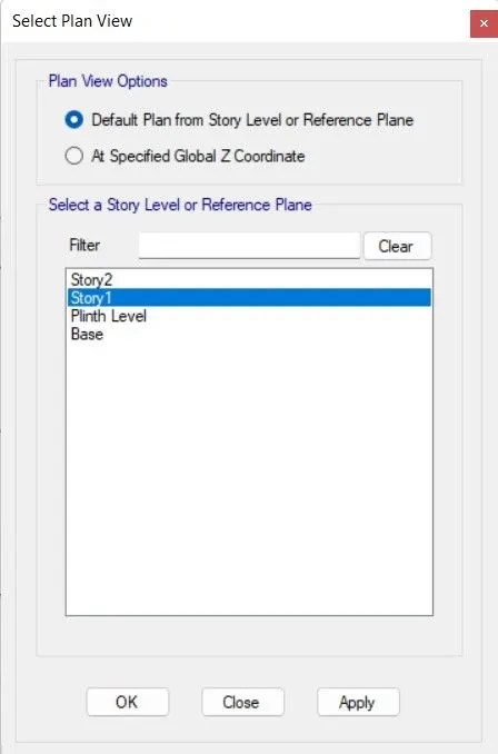
- Now draw the Slab.
- Draw slab of size 150mm thickness, Draw slabs with quick draw floor/wall keeping all the stories on.
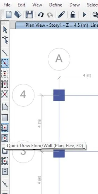
- Slabs are Successfully added to the structure.
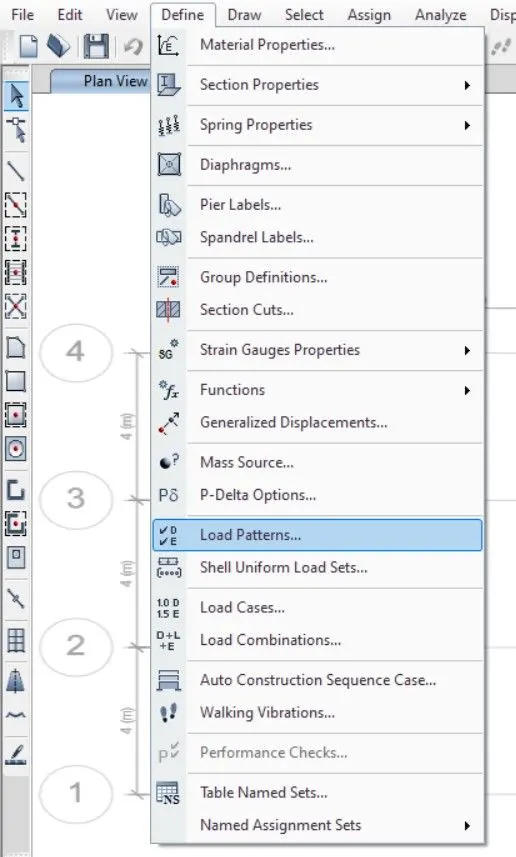
- Now define the load patterns.
- Click on the define tab and click on load patterns.
- Define the loads like dead load, live load, brick load, earthquake load in X direction and same loads in Y direction also.
- Mention IS codes of respective loads.
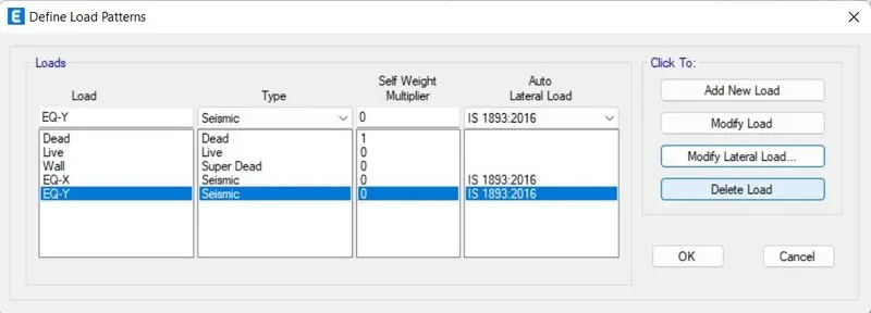
- Click on modified lateral load.
- Set range from base to 25th story and siesmic Zone factor as 0.36, important factor 1.25 and time perod 0.5 S.
- Now go to Mars Source from define tab.
- Modify the mars source and tick mark the required loads.
- Add load patterns and assign the model.
- Insert the dead load as multiplier to 1, live load as multiplier to 0.25 and wall load as multiplier to 1.
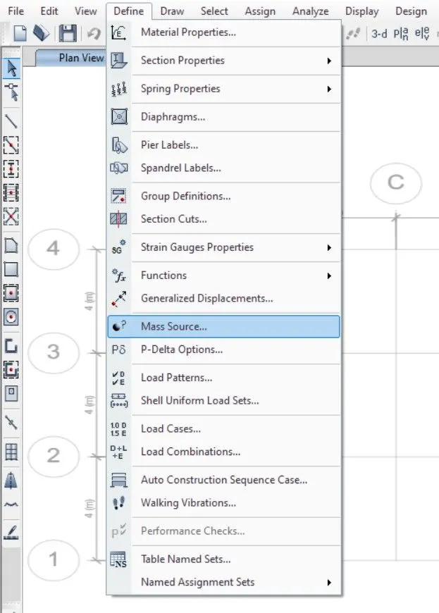
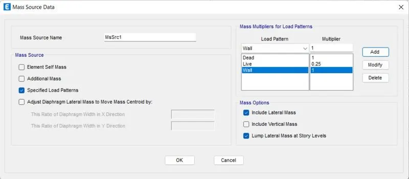
- Mars source is been added successfully.
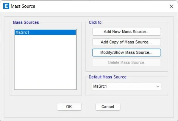
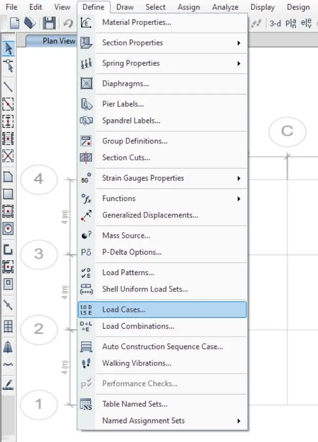
- Now go to Load cases in define Tab.
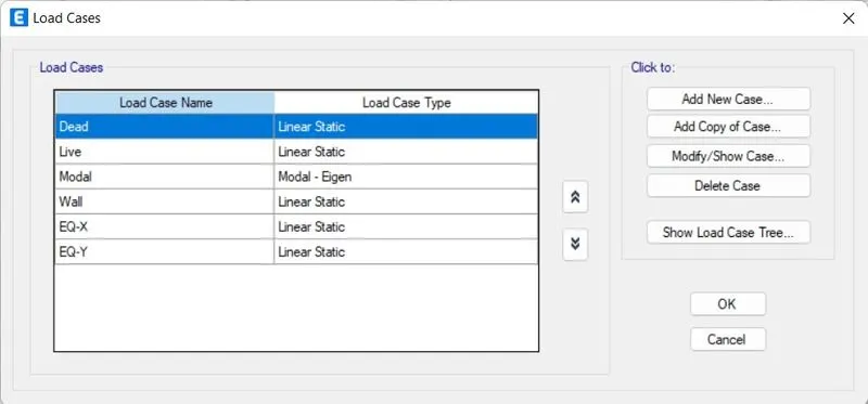
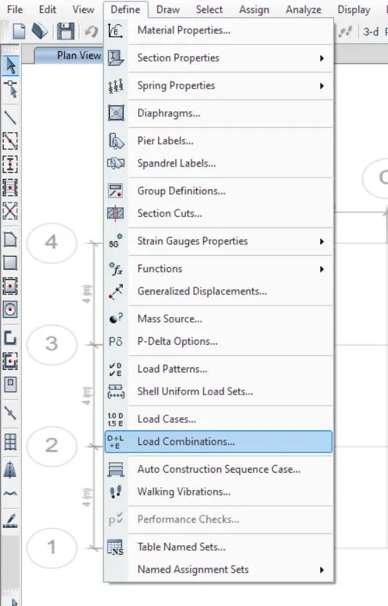
- Now go to Load combinations in define Tab.
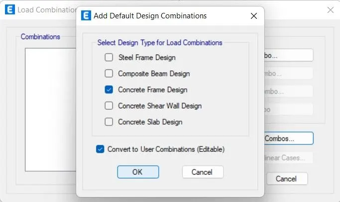
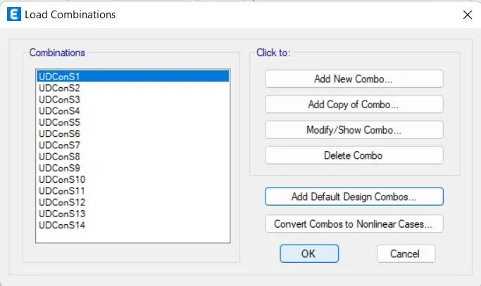
- Select add default design combos.
- Select concrete frame Design.
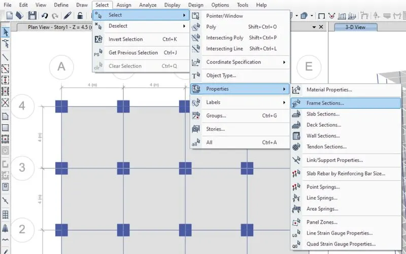
- Now go to Select option in select Menu.
- Slect Properties.
- Select Frame Sections.
- Select B400X300 option.
- Now assign the loads.
- Frame loads -> Distributed.
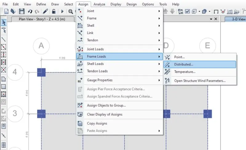
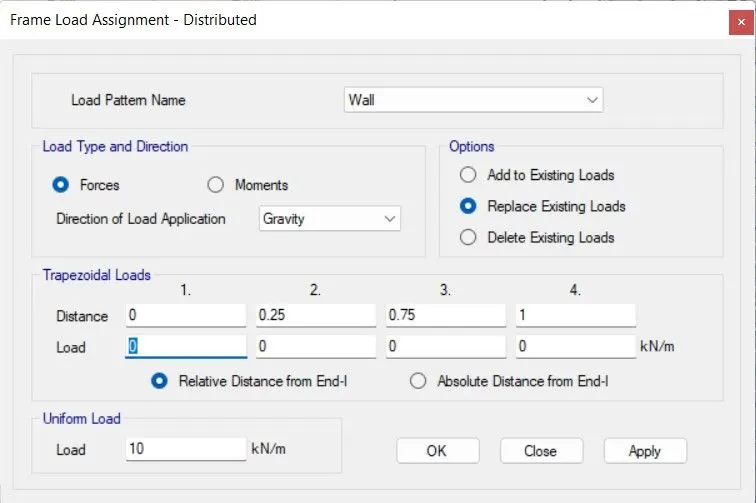
- Now go to Select option in select Menu.
- Slect Properties.
- Select slab Sections.
- Select All the Slab150.
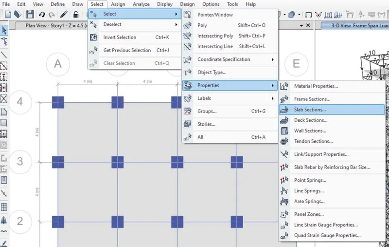
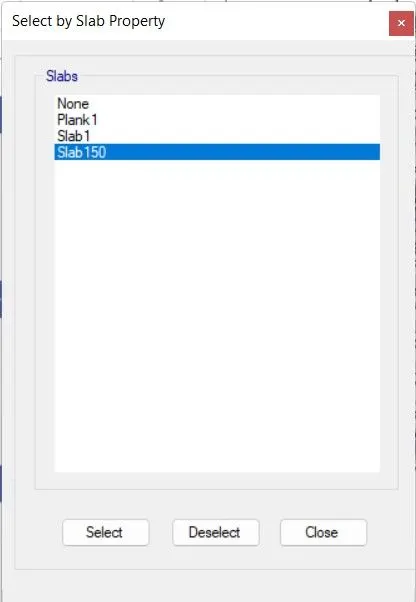
- Do the same process for all the earthquake load.
- Assign the loads and select in similar stories.
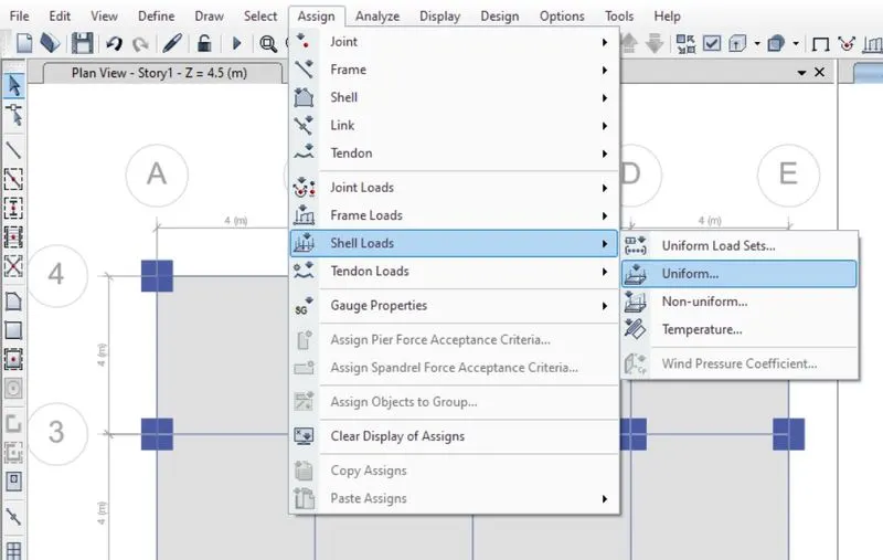
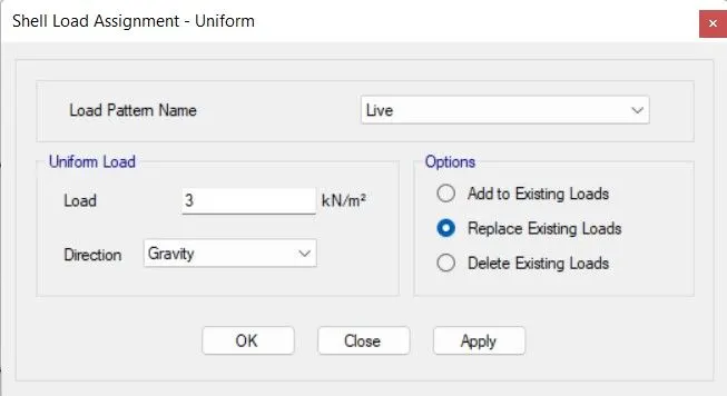
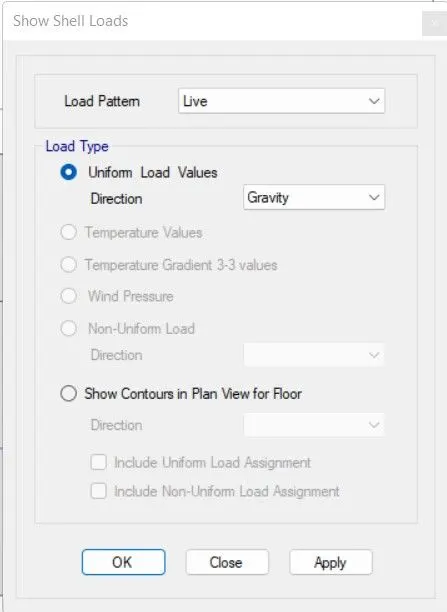
- Click on shell load under the assigne tab.
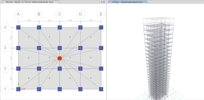
- Click on live load and give value as 3 kn/m^2.
- Click on apply.
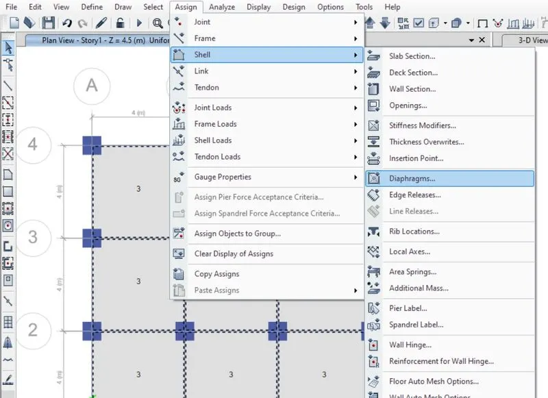
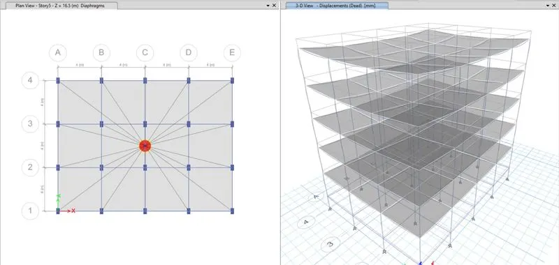
- Now create the diaphragm by going to the assign tab then shell and select diaphragm.
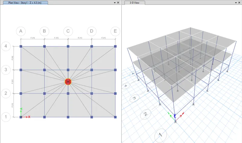
- Analyse the model using analyse option then click on check model the modelled structure is verified without errors and warnings.

- Using analyse -> Run analysis, the model is analysed and deflection pattersn are cross checked it logically it is understood that the V model provides reliable results
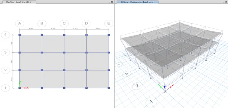
- Now save thi model as 'Model-a'.
- Save as this model as 'Model-b'.
2.Builging B (G+5)
- Now to model building B, we need not create a new file from scratch.
- Rather we will save a copy of the building A file and do the alterations needed for building B.
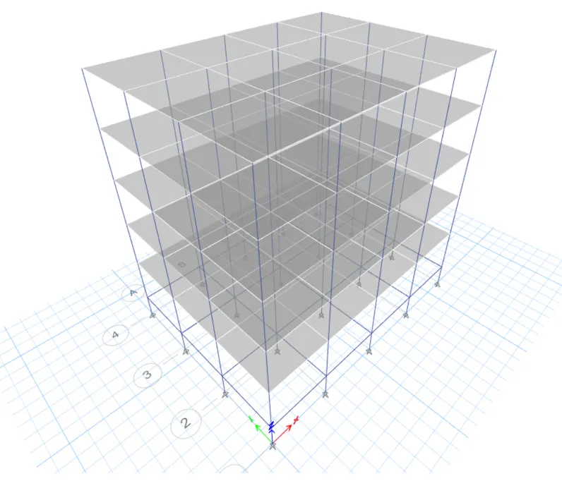
- For example, we can increase the number of stories to 5 by editing the story that are within the copied file.
- So the complete procedure to do so in Etabs as discussed below:
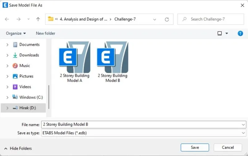
- Make a copy by Save As:
- From model A, go to files and click on the save as option.
- Set the destination folder and name it Building B.
- The model is set for changes as per requirements of Building B.
- Edit Story Data:
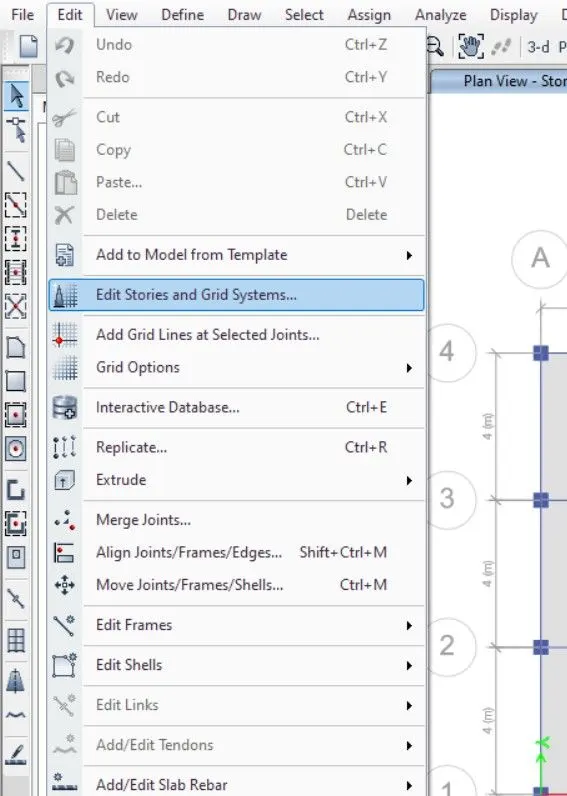
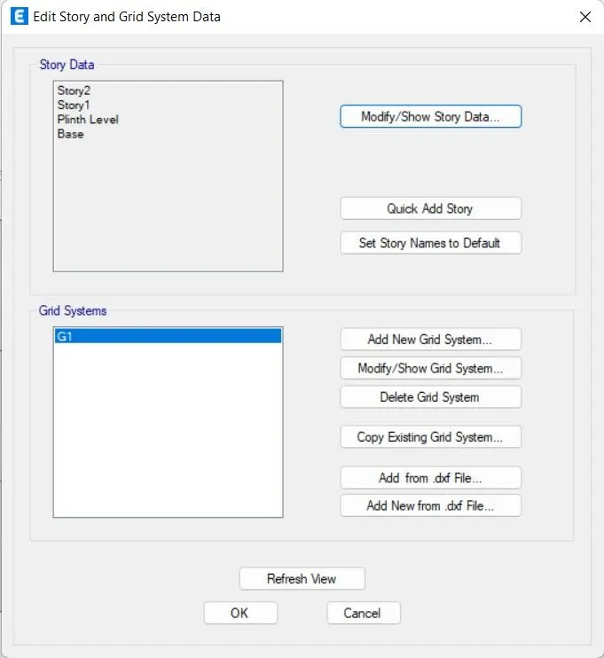
- From the new file, go to ->edit story and grid data.
- Click on the modified story data option.
- Then, right click on the top story and select the add story option.
- Set the height and the number of stories you want to add.
- In our case, we need to add 3 more floors to convert our 2 storey building to a 5-story one.
- Make each story similar to the master story related in model 1.
- Converted 5 Story Model:
- Check the model before running analysis:
- Now that our model is ready we need to get check for two to three things before running the analysis and noting the model period.
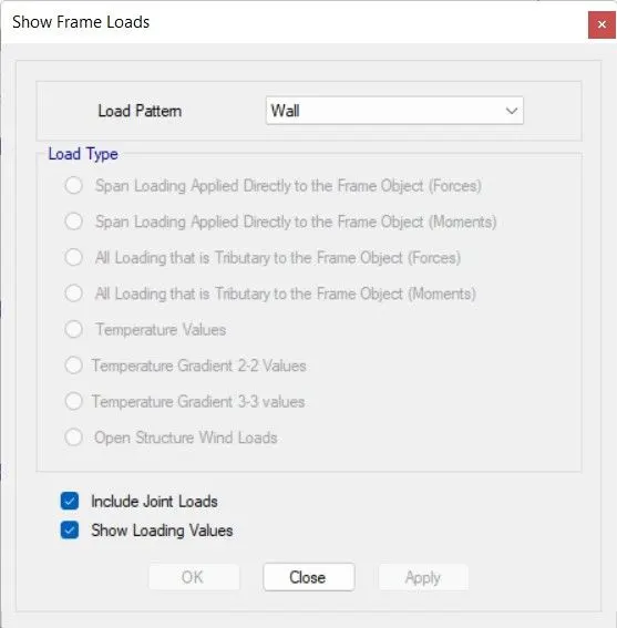
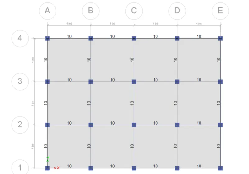
- The first check is for load assignments.
- From the bottom ribbon in Etabs, go to the show frame and shell loads one at a time.
- This way the model will show if the corresponding load has been assigned to the top floor.
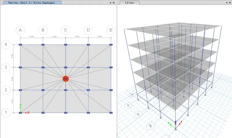
- Similarly, you need to check if the diaphragm has been assigned to the new model or not.
- You can check it by going to the view settings option and checking the diaphragm visibility.
- If the diaphragm is not visible you need to select all the floors and assign the diaphragm like we did it for the first model.
- Check for shell load:
- Check for Frame load:
- Run the Analysis:
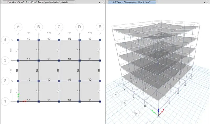
- Now that all the check have been made and the structure is ok, we can run the analysis.
- And to do that simply press the F5 button on your keyboard or click on the arrowhead available at the bottom ribbon in ETabs.
- It will take a few seconds and the deflected shape of the building will appear indicating that the analysis has been completed.
- Model response for Building B :-
3.Builging C (G+5 with Column orientation in X direction)
- The Story and grid data for building C remains same.
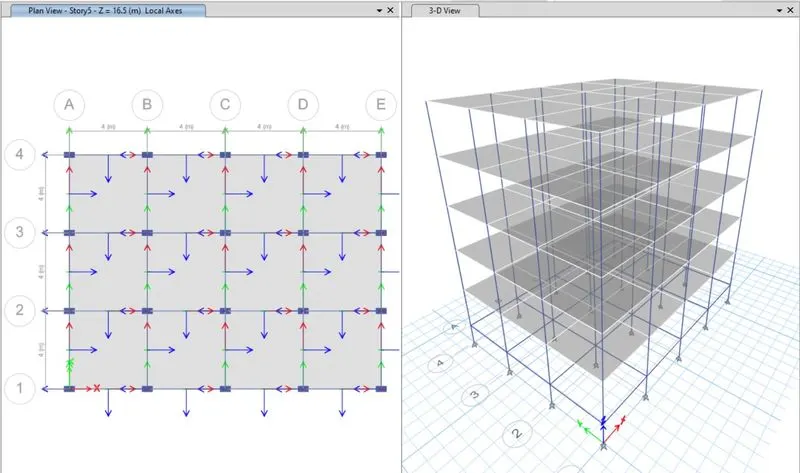
- However, we need to change the column size and orient and the same in X direction.
- So complete step by step procedure as discussed in detail below:
- Make a copy by Save As:
- Like we did for building B, now do it for Building C through Building B.
- Choose the appropriate location and save the file as Building C.
- Now the model is set to be edited is needed.
- Edit the column size and Orientation:
- To edit the column section, Go to define -> section properties -> frame section.
- Now select the previously created column for building A and B.
- Click on the modify/show properties option.
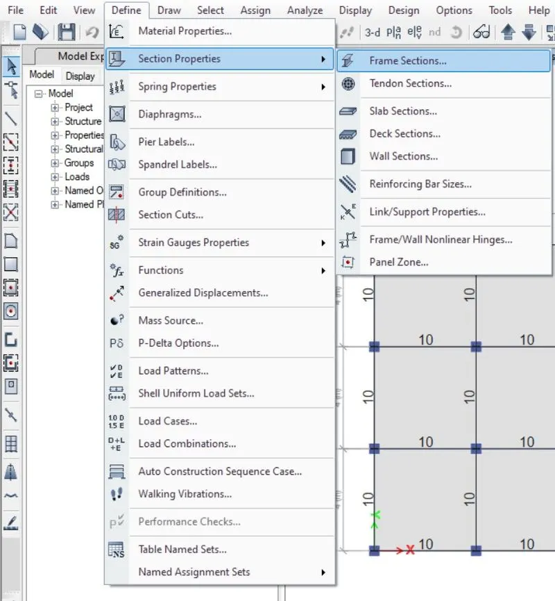
- Rename the column as needed which in our case is 550X300.
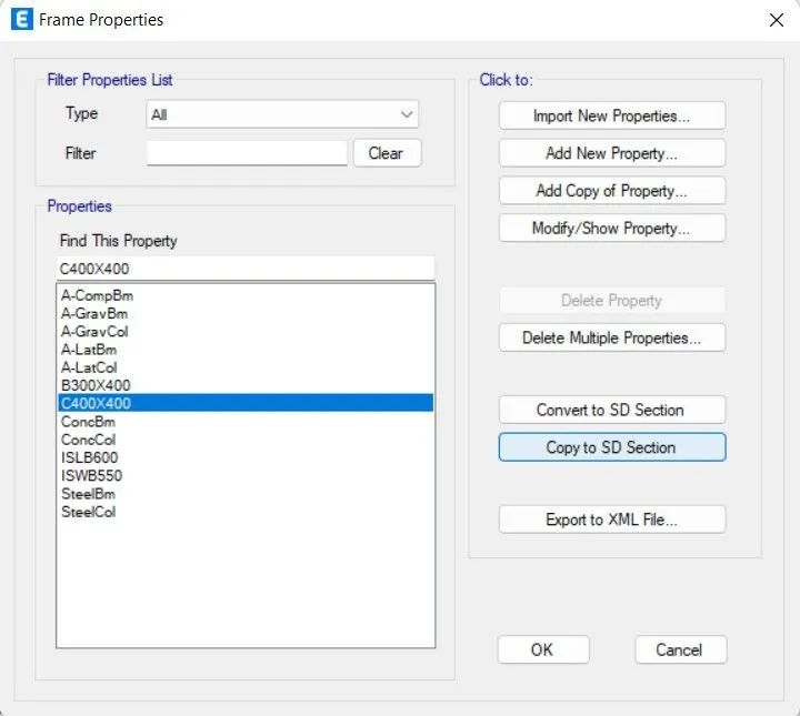
- Then, edit the length and breadth by entering the value in the box.
- Now we need to orient the 550 mm in the X direction.
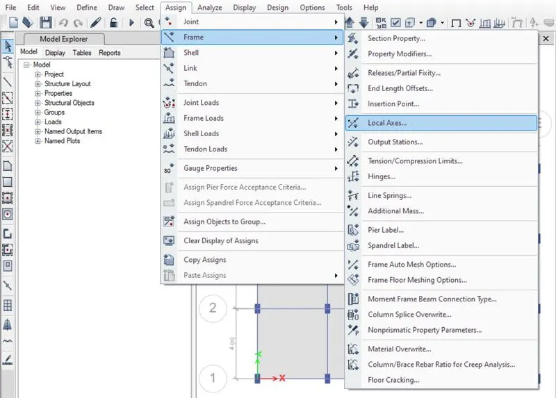
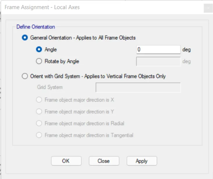
- So, select the column section then go to assign -> local axis -> rotate -> 90 degrees.
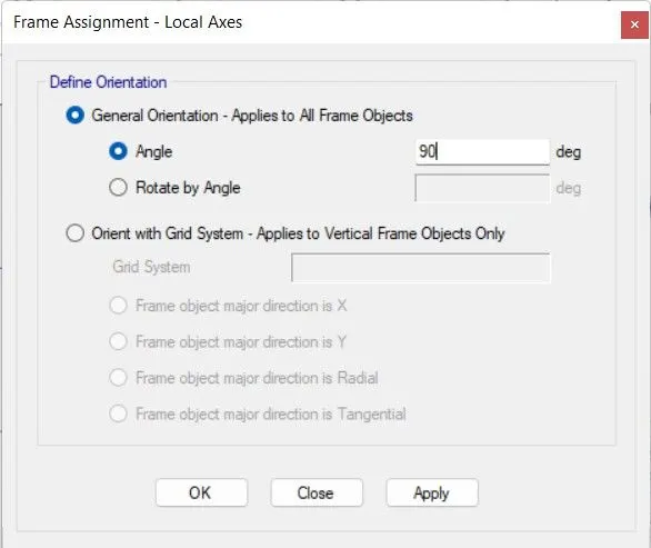
- This way all the columns shall be oriented in X direction meaning 550 mm laying down in X direction.
- Diaphgram Check :-
- Run the Analysis:
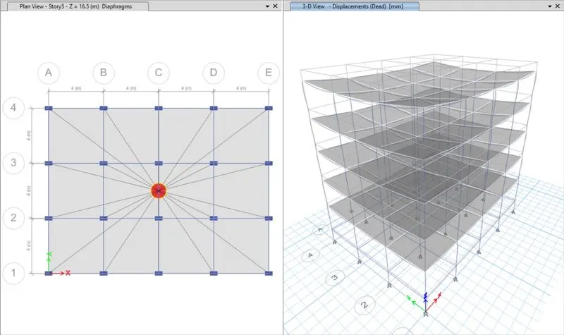
- Now that all the check have been made and the structure is ok, we can run the analysis.
- And to do that simply press the F5 button on your keyboard or click on the arrowhead available at the bottom ribbon in ETabs.
- It will take a few seconds and the deflected shape of the building will appear indicating that the analysis has been completed.
4.Builging D (G+5 with Column orientation in Y direction)
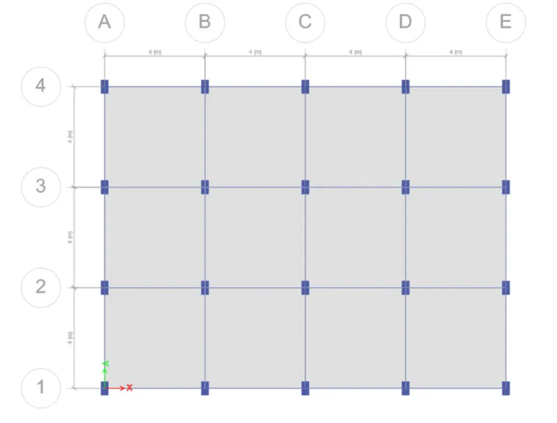
- The Story and grid data for building C remains same.
- However, we need to change the column size and orient and the same in Y direction.
- So complete step by step procedure as discussed in detail below:
- Make a copy by Save As:
- Like we did for Building C, now do it for Building D through Building C.
- Choose the appropriate location and save the file as Building C.
- Now the model is set to be edited is needed.
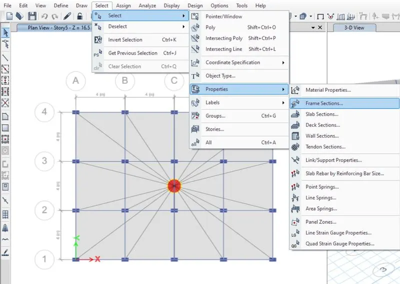
- Select the Column of size 550X300.
- So, select the column section then go to assign -> local axis -> rotate -> 0 degrees.
- Required Column Section:
- Run the Analysis:
- Now that all the check have been made and the structure is ok, we can run the analysis.
- And to do that simply press the F5 button on your keyboard or click on the arrowhead available at the bottom ribbon in ETabs.
- It will take a few seconds and the deflected shape of the building will appear indicating that the analysis has been completed.
5.Builging E (G+10)
- Column sizes for top 5 storeys : 400X400
- Column sizes for bottom 5 storeys : 600X600
- In this model we need to add 5 more stories to our model.
- In addition, we also need to assign different column sizes and different floors.
- Then we need to add 2 new column sections with required direction and assign them at appropriate floors in our model as specified.
- So, the stepwise procedure to be create new column and locate them on the part where is explained below
- Make a copy by Save As:
- Like we did for Building D, now do it for Building E through Building D.
- Choose the appropriate location and save the file as Building D.
- Now the model is set to be edited is needed.
- Add up five new stories and set the model for Building E:
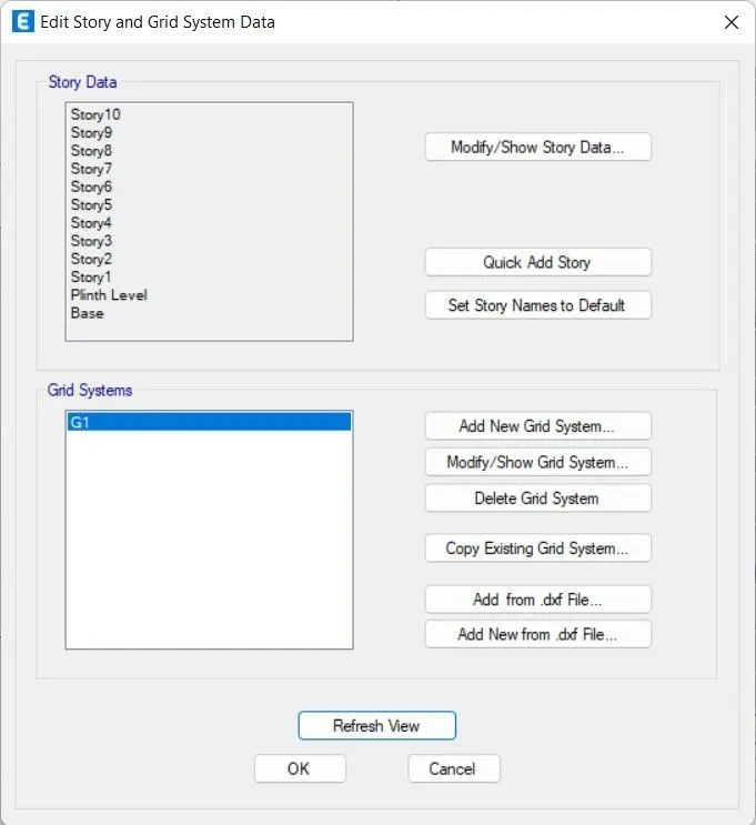
- From the new file, go to ->edit story and grid data.
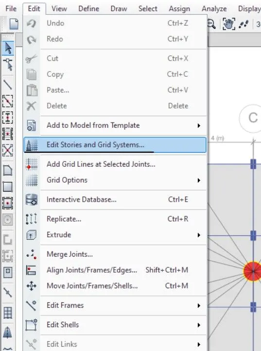
- Click on the modified story data option.
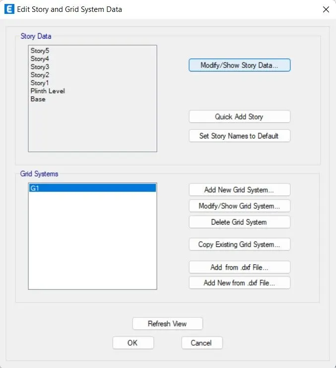
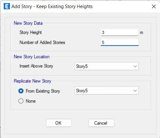
- Then, right click on the top story and select the add story option.
- Set the height and the number of stories you want to add.
- In our case, we need to add 3 more floors to convert our 2 storey building to a 5-story one.
- Make each story similar to the master story related in model 1.
- Check for shell load:
- Check for Frame load:
- To edit the column section, Go to define -> section properties -> frame section.
- Now select the previously created column for building A and B.
- Click on the modify/show properties option.
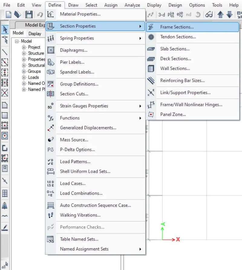
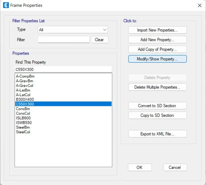
- Change the column size from 550X300 to 600X600.
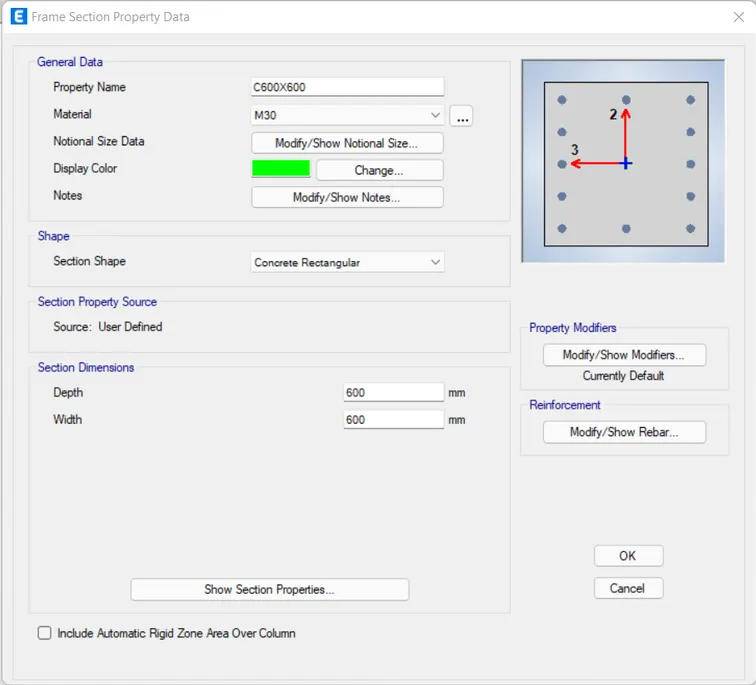
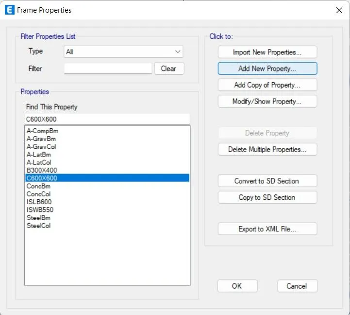
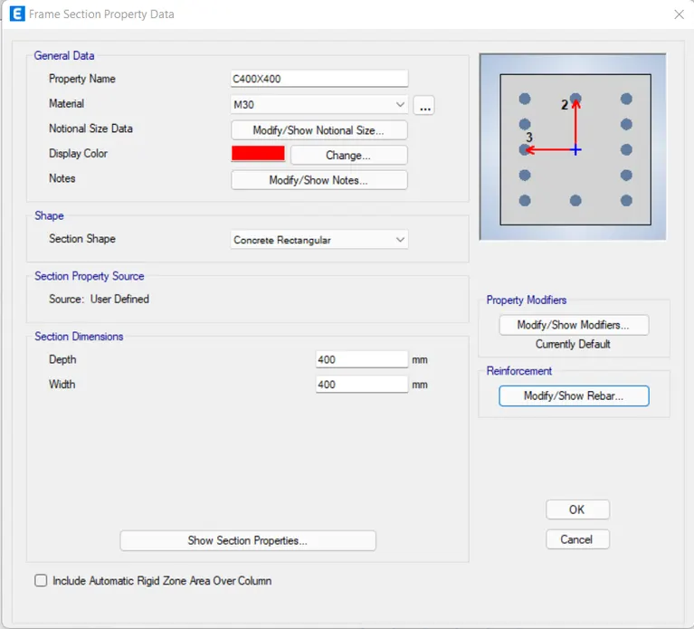
- Now create the new column of size 400X400.
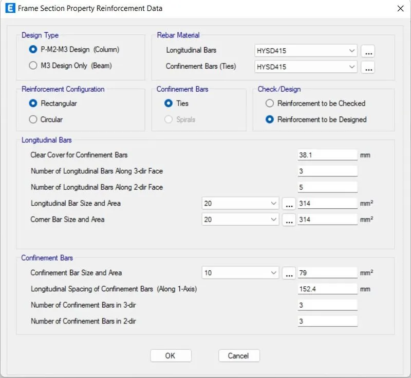
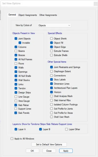
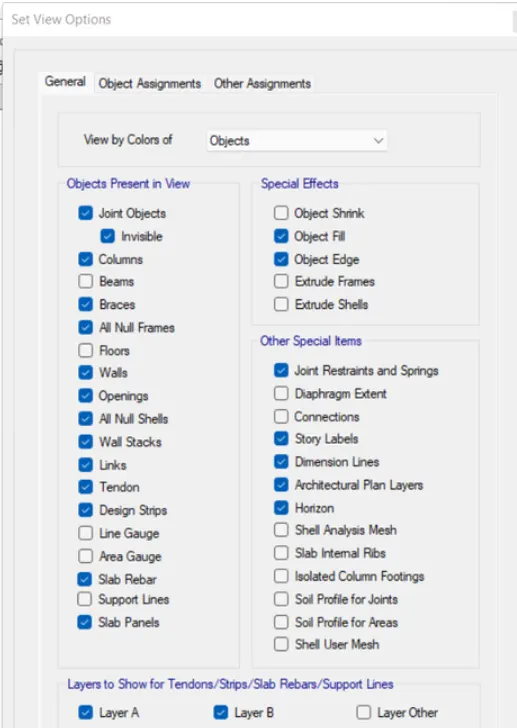
- Change the view settings of the model
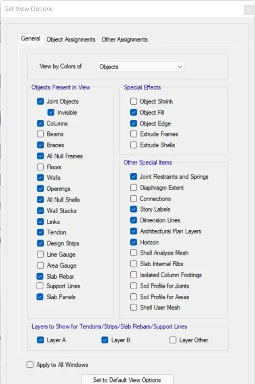
- There's an option in ETabs that allows users to adjust the model and view the only objects that are needed to be worked on currently.
- The tool is called view options settings.
- It is easily accessible from the front Ribbon of ETabs.
- So, you can go to your options settings and uncheck the structural member that you want to hide currently for modelling.
- As we need to assign different column sizes in our model we don't need to view beams and columns currently.
- So we go to the tool and unchecked beams and floors in order to make the only columns visible for editing.
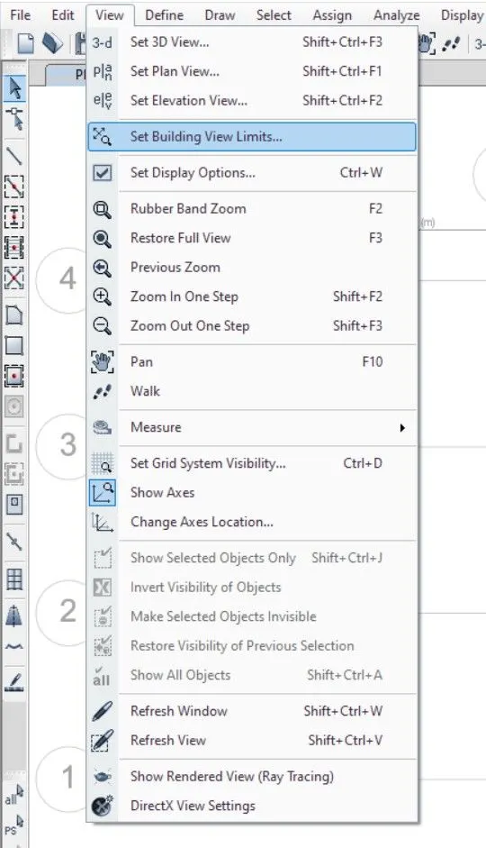
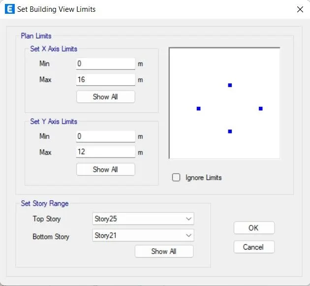
- Set the Building Limit, Select columns and assigned them the required sections
- Now since we need to different columns for the top five floor and different columns for the bottom 5 .
- Therefore, we need to edit the top and bottom five stories one after the other.
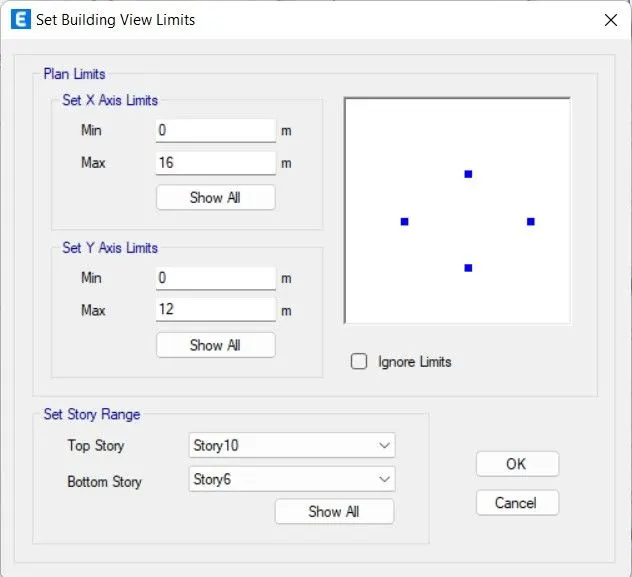
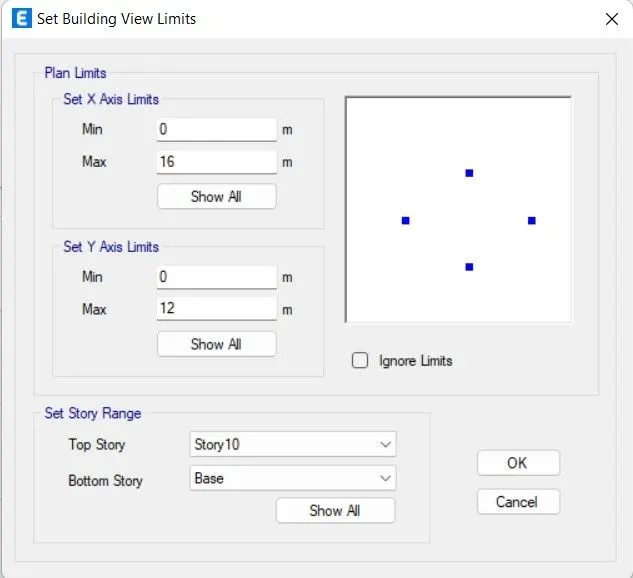
- So we need first set the building limits up to the bottom 5 floors and vice versa.
- And to do that, you can go to edit -> Set Building limits.
- The Set Building limits option in Etabs allows you to view only the floors that you need to work on.
- Hence, first we set the limit to top 5 -> select all the columns by holding the left click and making the box around the entire model -> go to assign and assign them the required column section.
- Repeat the procedure for the rain in top columns and complete with the model.
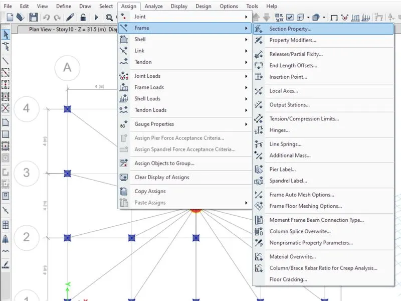
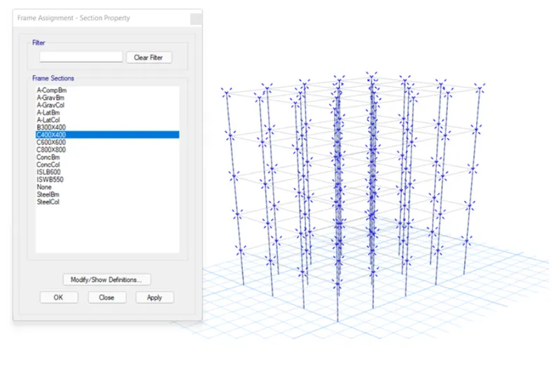
- Go to assign -> Frame -> Section Property and assign them column size of C400X400.
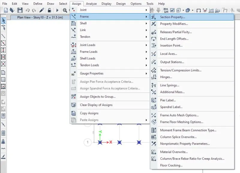
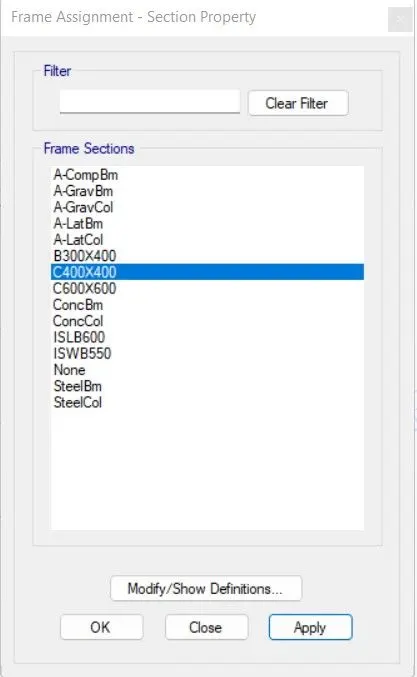
- So the top 5 story columns are assigned wth the size of 400X400.
- Hence, first we set the limit to bottom 5 -> select all the columns by holding the left click and making the box around the entire model -> go to assign and assign them the required column section.
- Repeat the procedure for the rain in top columns and complete with the model.
- So the top 5 story columns are assigned wth the size of 400X400 and bottom 5 story columns are assigned wth the size of 600X600.
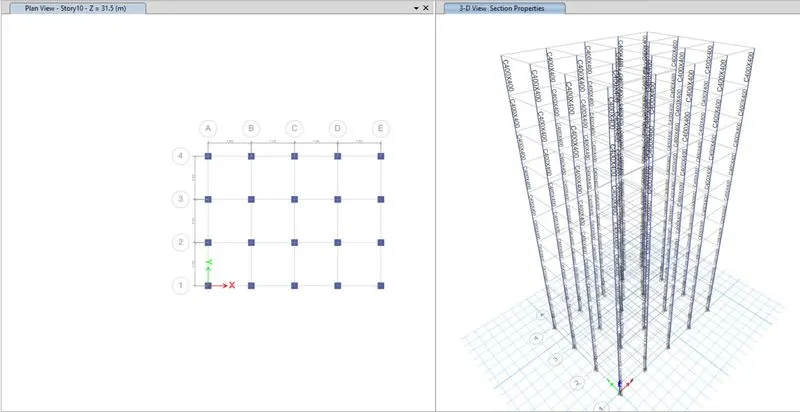
- Now create the diaphragm by going to the assign tab then shell and select diaphragm.
- Run the Analysis:
- Now that all the check have been made and the structure is ok, we can run the analysis.
- And to do that simply press the F5 button on your keyboard or click on the arrowhead available at the bottom ribbon in ETabs.
- It will take a few seconds and the deflected shape of the building will appear indicating that the analysis has been completed.
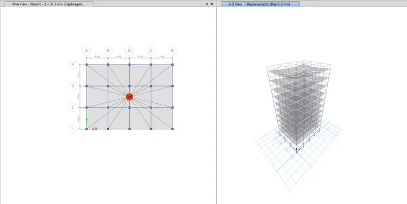
6.Builging F (G+10)
- Column sizes for throughtout the structure : 600X600
- Make a copy by Save As:
- Like we did for Building E, now do it for Building F through Building E.
- Choose the appropriate location and save the file as Building E.
- Now the model is set to be edited is needed.
- Adjust view option setting:
- This building has the same columns for the entire structure,
- Therefore, we don't need to do much editing in terms of the section.
- We just need to adjust the view settings -> hide beans and floors -> select all the columns -> assigned them frame section properties of C660X600.
- Select Frame -> Section Property.
- Select all the columns.
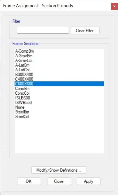
- So all the columns are assigned with the size of C600X600.
- Run the Analysis:
- Now that all the check have been made and the structure is ok, we can run the analysis.
- And to do that simply press the F5 button on your keyboard or click on the arrowhead available at the bottom ribbon in ETabs.
- It will take a few seconds and the deflected shape of the building will appear indicating that the analysis has been completed.
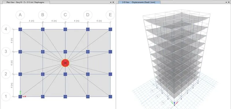
7.Builging F (G+25)
- Column sizes for top 5 storeys : 400X400
- Column sizes for middle 5 storeys : 600X600
- Column sizes for bottom 5 storeys : 800X800
- In this model we need to add 15 more stories to our model.
- In addition, we also need to assign different column sizes and different floors.
- Then we need to add 2 new column sections with required direction and assign them at appropriate floors in our model as specified.
- So, the stepwise procedure to be create new column and locate them on the part where is explained below.
- Make a copy by Save As:
- Like we did for Building E, now do it for Building F through Building E.
- Choose the appropriate location and save the file as Building E.
- Now the model is set to be edited is needed.
- Add up fifteen new stories and set the model for Building E:
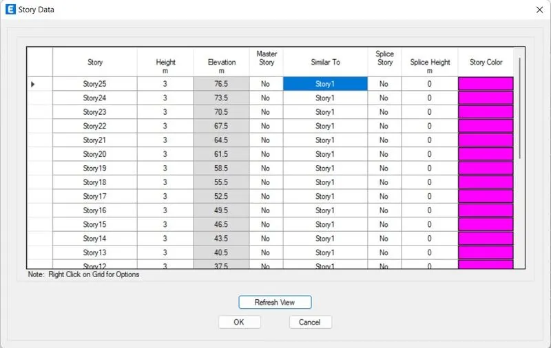
- From the new file, go to ->edit story and grid data.
- Click on the modified story data option.
- Then, right click on the top story and select the add story option.
- Set the height and the number of stories you want to add.
- In our case, we need to add 3 more floors to convert our 10 storey building to a 15-story one.
- Make each story similar to the master story related in model 1.
- Check for shell load:
- Check for Frame load:
- To edit the column section, Go to define -> section properties -> frame section.
- Now select the previously created column for building A and B.
- Click on the modify/show properties option.
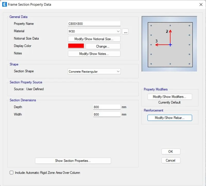
- Add the column of size C800X800.
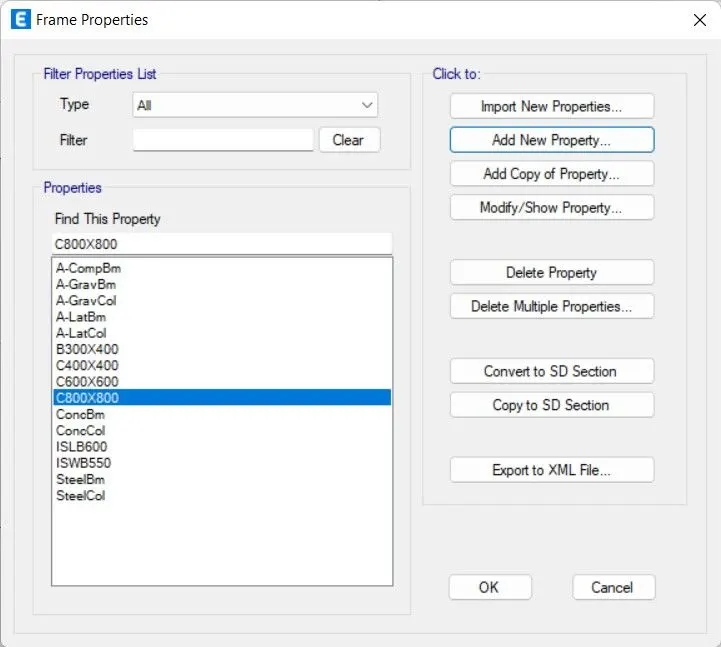
- Now all the 3 columns are added to the frame.
- View Settings:
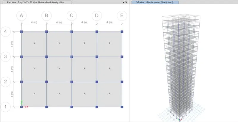
- Set Building Limit from 21-25:
- Select all the column and assign 400X400:
- Set Building Limit from 11-20:
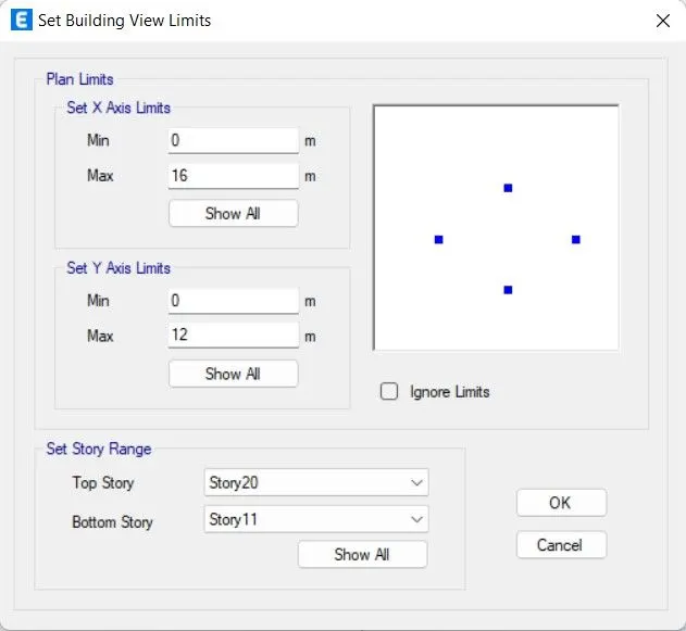
- Select all the column and assign 600X600:
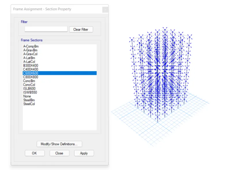
- Set Building Limit from 1-10:
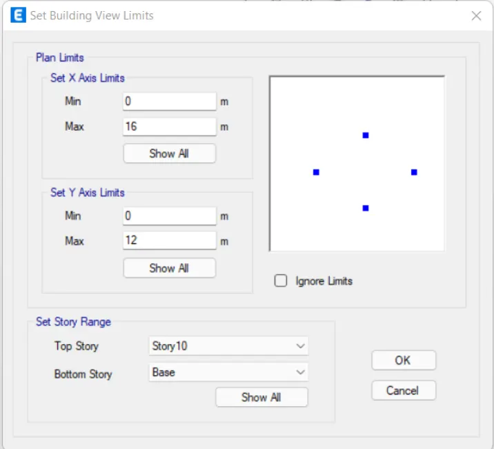
- Select all the column and assign 800X800:
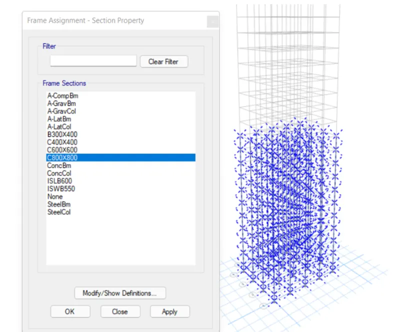
- So aal the sizes of columns are added to the srructure.
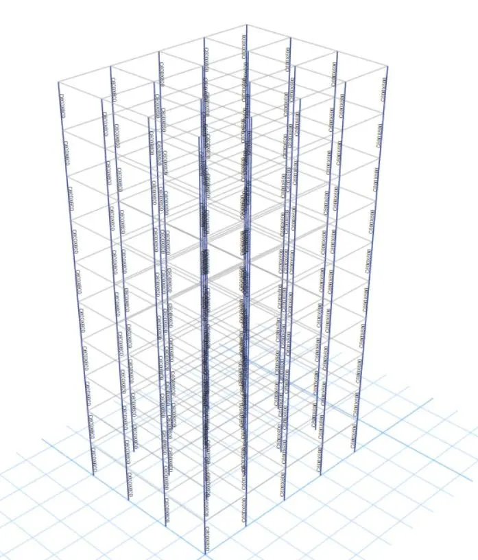
- Run the Analysis:
- Now that all the check have been made and the structure is ok, we can run the analysis.
- And to do that simply press the F5 button on your keyboard or click on the arrowhead available at the bottom ribbon in ETabs.
- It will take a few seconds and the deflected shape of the building will appear indicating that the analysis has been completed.
8.Builging H (G+25)
- Column sizes for throughtout the structure : 600X600
- Make a copy by Save As:
- Like we did for Building E, now do it for Building F through Building E.
- Choose the appropriate location and save the file as Building E.
- Now the model is set to be edited is needed.
- Adjust view option setting:
- This building has the same columns for the entire structure,
- Therefore, we don't need to do much editing in terms of the section.
- We just need to adjust the view settings -> hide beans and floors -> select all the columns -> assigned them frame section properties of C660X600.
- Select Frame -> Section Property.
- Select all the columns.
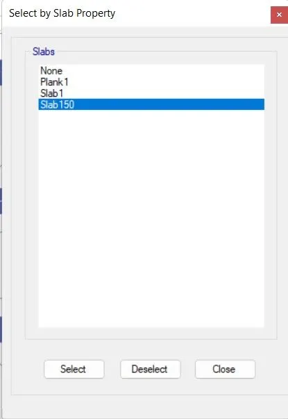
- So all the columns are assigned with the size of C800X800.
- Run the Analysis:
- Now that all the check have been made and the structure is ok, we can run the analysis.
- And to do that simply press the F5 button on your keyboard or click on the arrowhead available at the bottom ribbon in ETabs.
- It will take a few seconds and the deflected shape of the building will appear indicating that the analysis has been completed.
9.Builging J (G+25)
- 10% increment in imposed load.
- Building J is the Copy of the model H and we don't need to alter anything related to the modelling.
- However we need to increase the imposed load on the building by 10 percentage which is assigned as 3Kn/m^2 on all the slab of the buildings.
- Select the slab
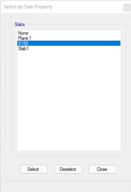
- Go to Assign -> Shell Loads -> Uniform -> Increase it by 10%.
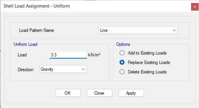
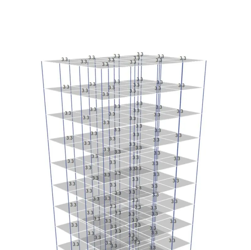
- Run the Analysis:
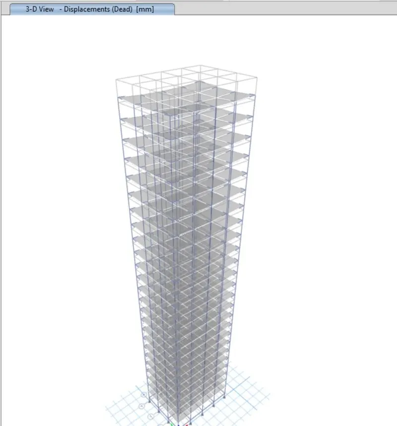
- Now that all the check have been made and the structure is ok, we can run the analysis.
- And to do that simply press the F5 button on your keyboard or click on the arrowhead available at the bottom ribbon in ETabs.
- It will take a few seconds and the deflected shape of the building will appear indicating that the analysis has been completed.
10.Builging K (G+25)
- 20% increment in imposed load.
- Building K is the Copy of the model J and we don't need to alter anything related to the modelling.
- However we need to increase the imposed load on the building by 20 percentage which is assigned as 3Kn/m^2 on all the slab of the buildings.
- Select the slab
- Go to Assign -> Shell Loads -> Uniform -> Increase it by 10%.
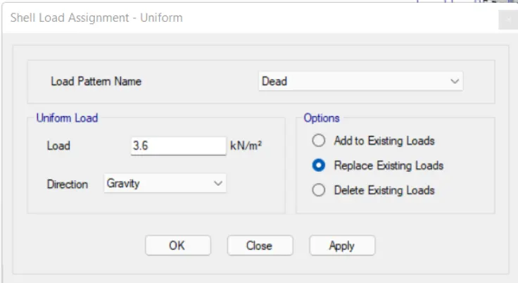
- Run the Analysis:
- Now that all the check have been made and the structure is ok, we can run the analysis.
- And to do that simply press the F5 button on your keyboard or click on the arrowhead available at the bottom ribbon in ETabs.
- It will take a few seconds and the deflected shape of the building will appear indicating that the analysis has been completed.
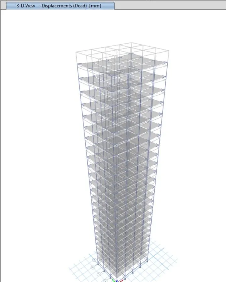
Results :-
- As we have completed the modelling and analysis of different story buildings in previous stage of project, now we are going to compare those results and try to understand the change in behaviour of building based on their structural geometries.
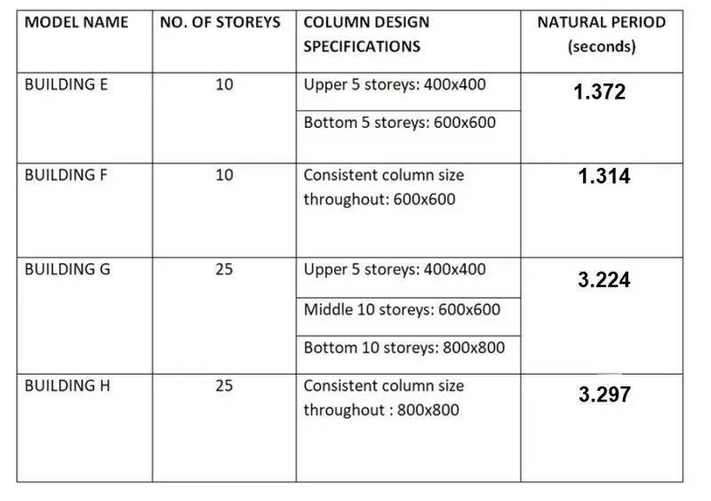
Effect of stiffness on T: Compare fundamental natural periods of buildings E & F as well as G & H. Why is there a marginal or significant difference in the fundamental natural periods?
Comparitive Model :-
Conclusion :-
- For Builging E and F, varying column design doesn't make a big difference as there are only 5 stories.
- However, we can see that for buildings G and H, consistent column size throughout the structure causes a more natural period.
- It can be concluded that providing larger columns at the base and then reducing the size on top floors helps controls the natural period.
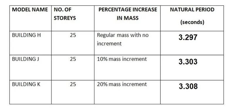
Effect of mass on T: Compare fundamental natural periods of buildings H, J and K. Have the buildings become more flexible or stiff due to change in mass?
Comparitive Model :-
Conclusion :-
- The Natural period for tall buildings is directly proportional to imposed mass of the building.
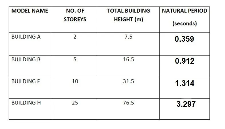
Effect of Building Height on T: How does the fundamental natural periods of Buildings A, B, F and H change with change in building height?
Comparitive Model :-
Conclusion :-
- The Natural period for tall buildings is directly proportional to imposed mass of the building.
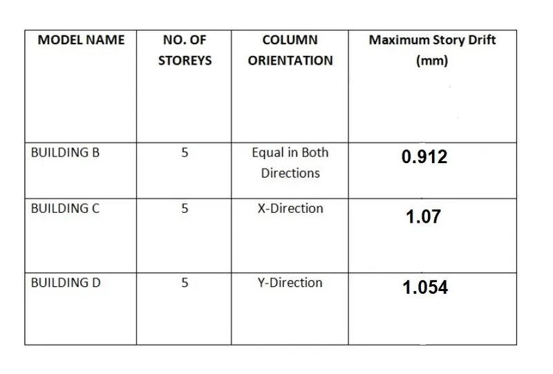
Effect of Column Orientation on T: How does the fundamental natural periods of Buildings B, C and D change with change in column orientation?
Comparitive Model :-
Conclusion :-
- When the column cross-section is square, there is not much difference between lateral displacement in both the orthogonal directions.
- When you orient the column in particular directions be it X and Y, lateral displacement in particular direction will be less than that in other direction which has a lesse column length.
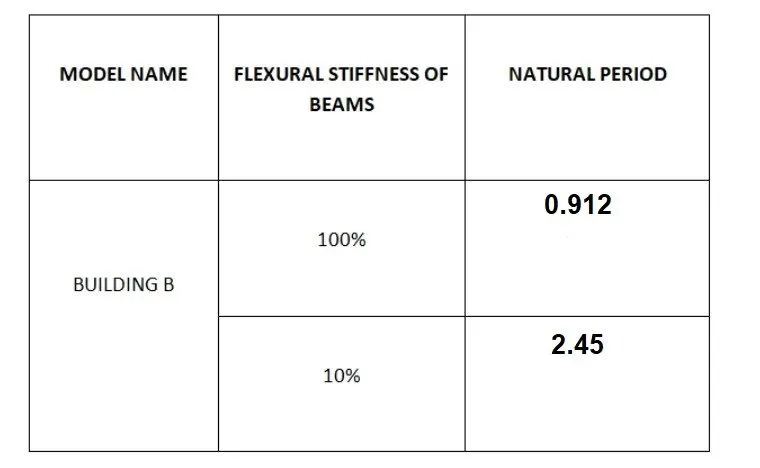
Effect of Flexural Stiffness of Structural Elements on mode shapes: Compare fundamental mode shape of Building B in two situations when flexural stiffness of beams relative to that of adjoining columns is very small versus when it is large.
Comparitive Model :-
Conclusion :-
- It is pretty obvious that if you decrease the flexural stiffness of beams, the overall flexural strength of the beam is also going to reduce, the fundamental natural period will shoot up.
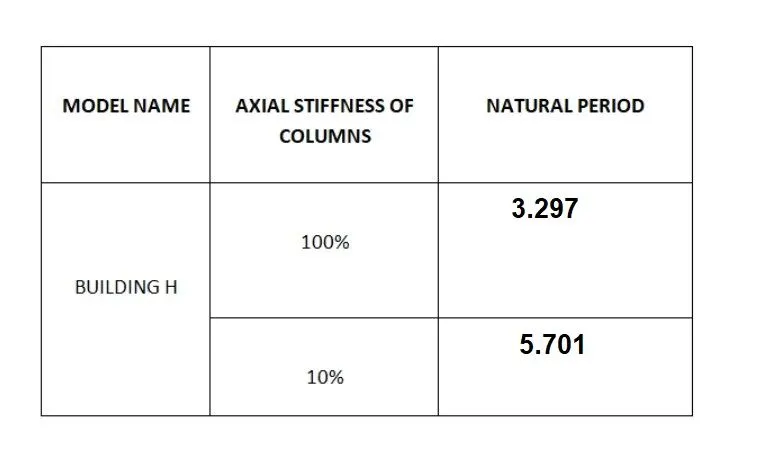
Effect of Axial Stiffness of Vertical Members on mode shapes: Compare fundamental mode shape of Building H in two situations when axial cross-sectional area of columns is very small versus when it is large.
Comparitive Model :-
Conclusion :-
- As the Axial Stiffness of Vertical Member decreases, fundamental mode shape of Building increases regardless of its structural geometry.
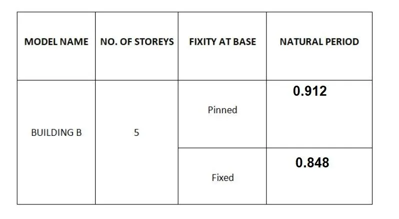
Effect of Degree of Fixity at column bases on mode shape: Compare fundamental mode shape of Building B in two situations when base of columns is pinned versus when it is fixed.
Comparitive Model :-
Conclusion :-
- It is evident that pinned support offers fewer restraint compared to fixed one which lead to more movement and thus increased natural period.