Project 1_Comparative study of different storey buildings for Seismic forces
Aim : To study and compare the results of
- Factors influencing the dynamic characteristics of different storey building for seismic force
- Factors influencing the Natural Period of different storey building for seismic force
- Factors influencing the Mode shape of oscillations of different storey building for seismic force.
Introduction : ETABS is an engineering software product that caters to multi-story building analysis and design. Modeling tools and templates, code-based load prescriptions, analysis methods and solution techniques, all coordinate with the grid-like geometry. Basic or advanced systems under static or dynamic conditions may be evaluated using ETABS. For a sophisticated assessment of seismic performance, modal and direct-integration time-history analyses may couple with P-Delta and Large Displacement effects.
Procedure:
Model A:
Step 1:
- In this , we are suggested to create 2 story buidling with said column and beam sizes.
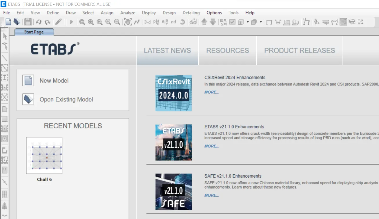
- So to create the model.Open the new model and save the model as Model A.
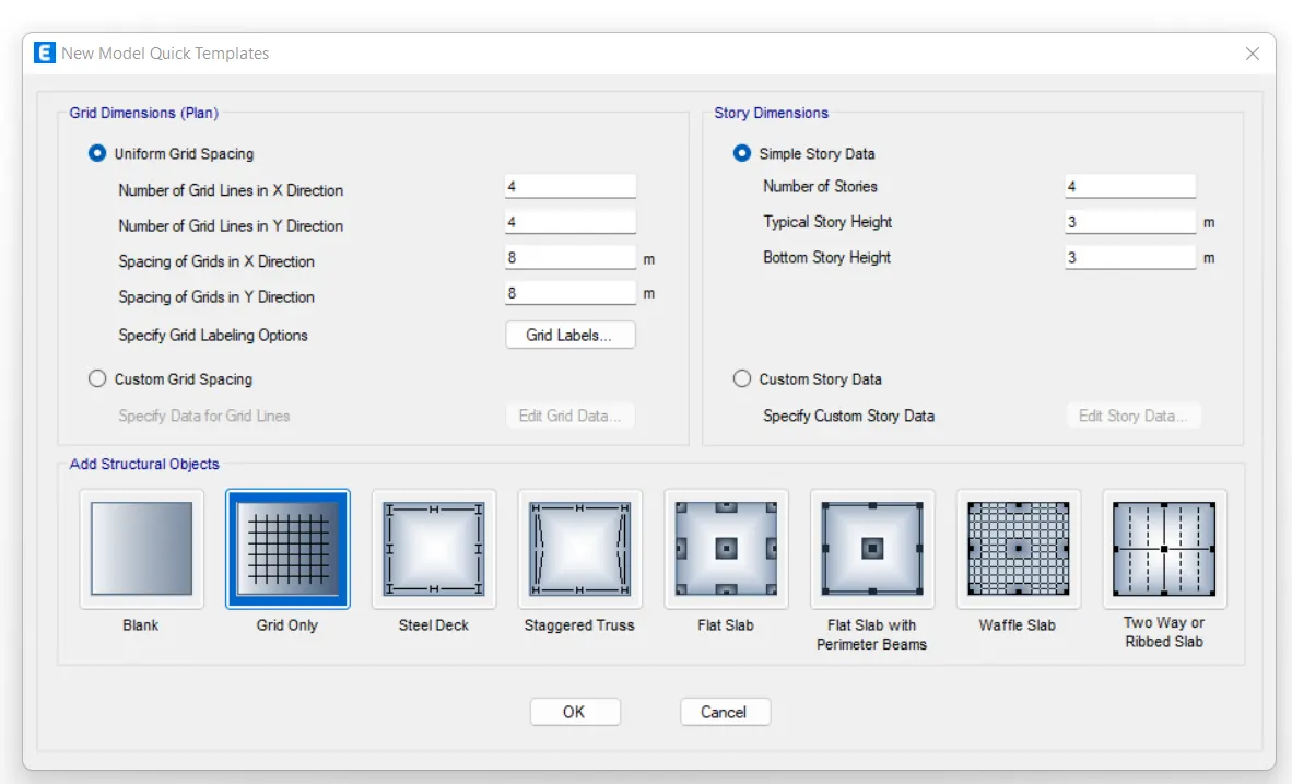
- Now first of all we need to set the story and grid data to place the beams, column and slabs in the model.
- So go to edit setting in the tool bar and open edit story and grid settings.
- In that change the setting to customize grid and stroy data.First let us customize the grids which is going to be permanent grid setting throughout the model.
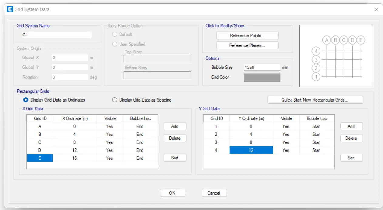
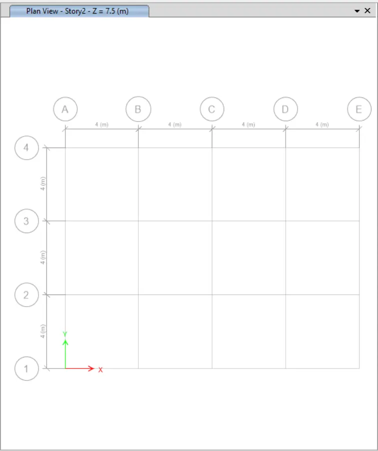
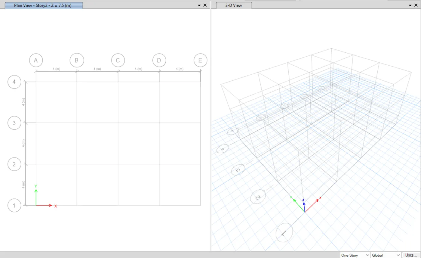
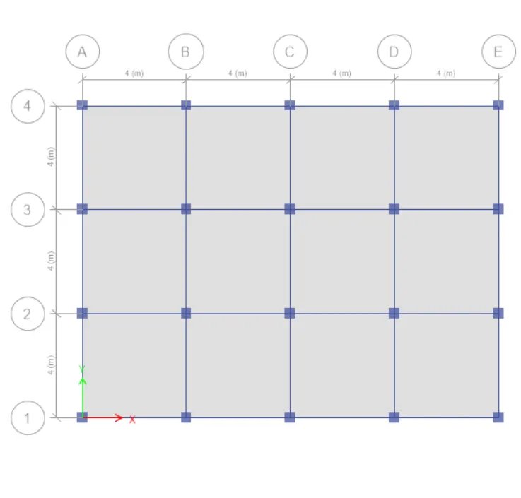
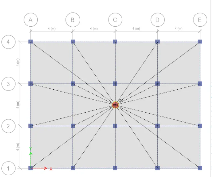
- As suggested we need 5 grids in the X direction adn 4 grids in the Y direction.
- The grid distance to be set in 4m between all grids.
- Thus created grid data is shown below
Step 2:
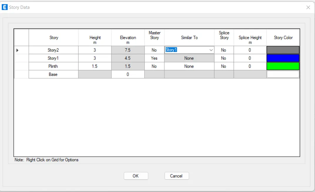
- After the creation of the grid data we need to edit the story data.
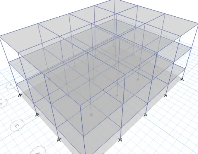
- Now by choosing the edit story option.We need to creat 2 story excluding plinth and base.
- The story distance here we are setting as 3m between each story as standard story heights.
- To add story we need to right click on the arrow mark on the left side of the last story and edit the additional story settings.
- After adding the story to the existing story data.We need to make the story1 as master story not the plinth or base.
- As the remaining story to be marked as the similar story to story 1.
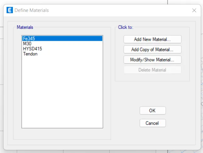
- Now we need to define the material properties of the components to be used in the model.
- To define the material prperties of the components we need to define the material to be used.
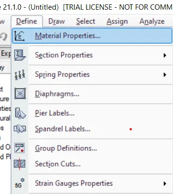
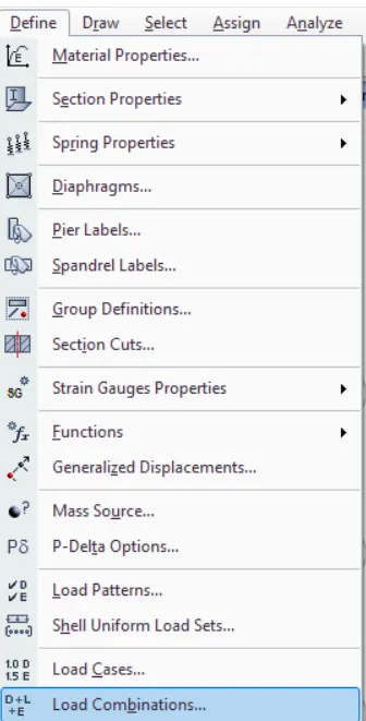
- So, go to the define option on teh tool bar and in the define option choose material properties.
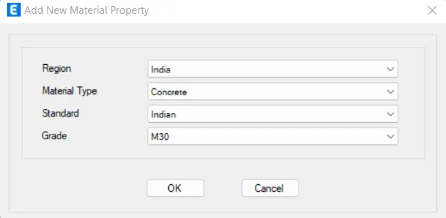
- In material properties create a new material by clicking add new material.
- Now we need to create concrete material, in this whole project we are going to use M30 grade concrete as teh standard concrete grade.
- Hence setting the grade as M30., and checking all other parameter of the concrete we can the add teh created material property.
Step 3:
- In this whole project we are going to use the above created material properties as the standard property for all the models to be created.
- Hence the material property was created.
- Now let us create the modeling elements like , beams, column and slab.
- The size of the column, beam and slab varies with each model.
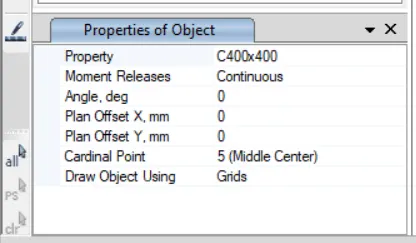
- For the model A we are goin to create column size as 400x400mm, Beam as 300x400mm and slab thickness as 150mm.Initialy creating the beam.
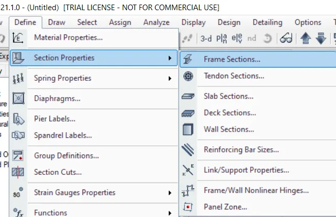
- To create the sections go to the define option in the tool bar and then select section properties.
- In section properties we need to add the required section.
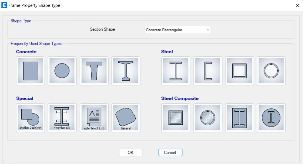
- First is beam so seelct the concrete rectangular section.And then add the sizes and add the material type in teh sections.Thus the beam is created.
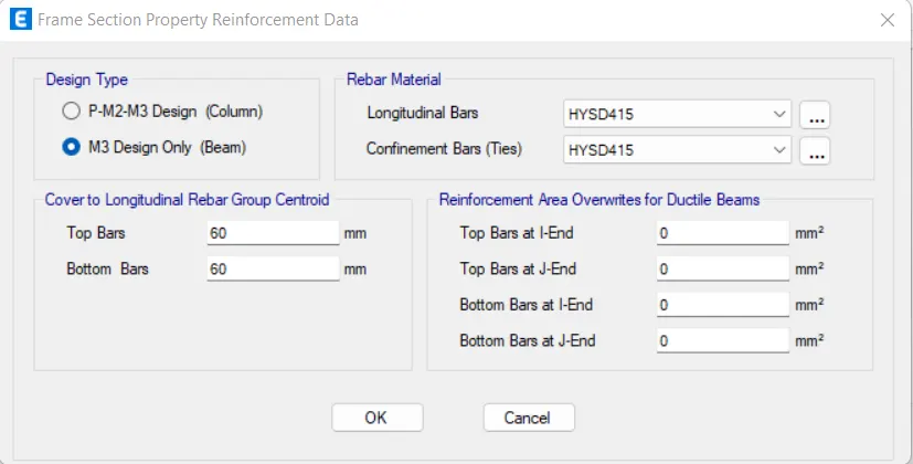
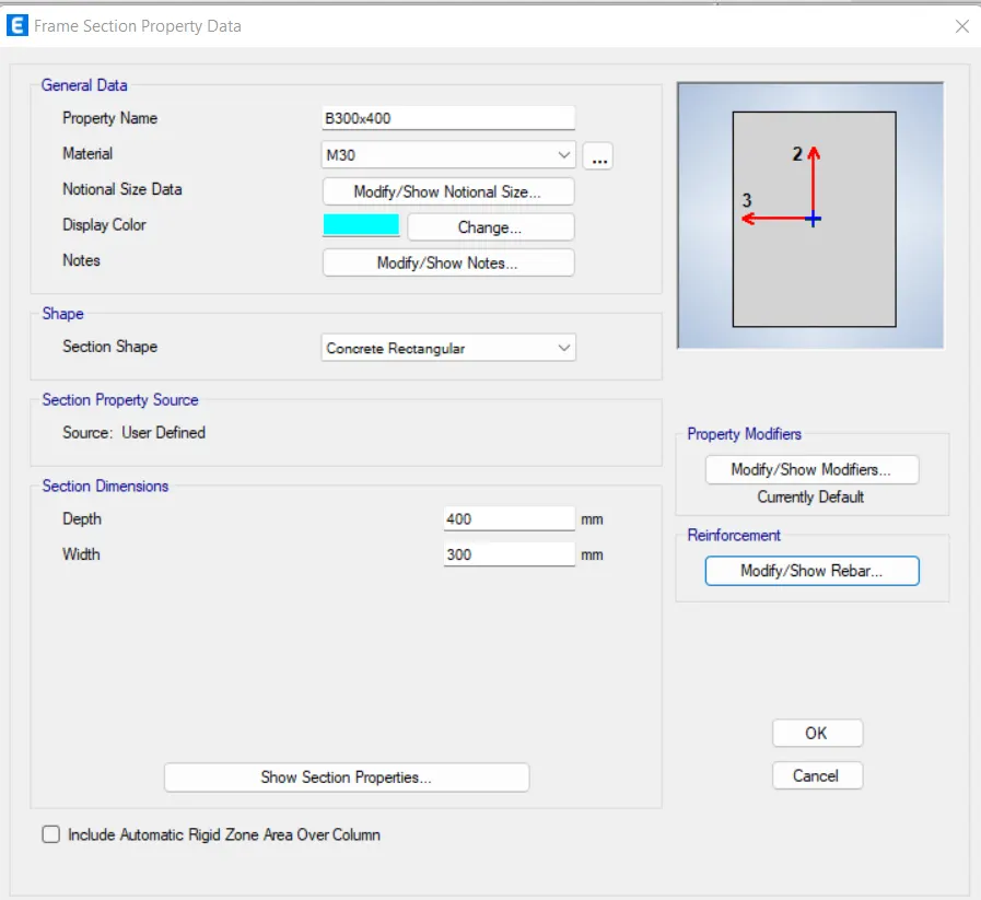
- After the beams create the column section.
- By adding the new section property as concrete section.
- And setting up teh required column size for the model A.
- And adding the required material for the section.
- Thus the column is created.
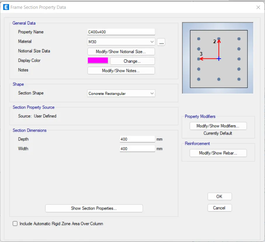
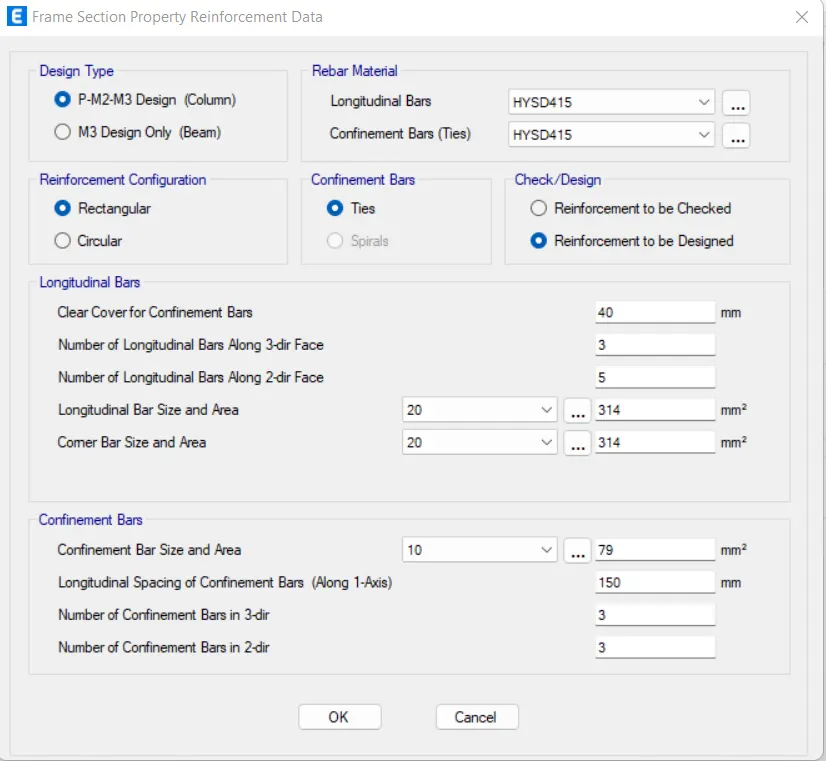
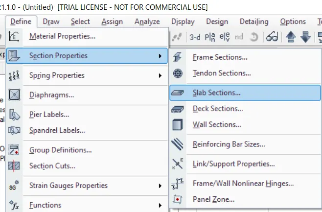
- To create slab section we need select define option as did before and section properties in that slab sections.
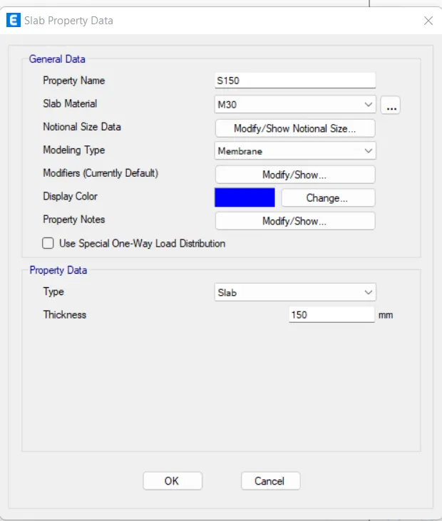
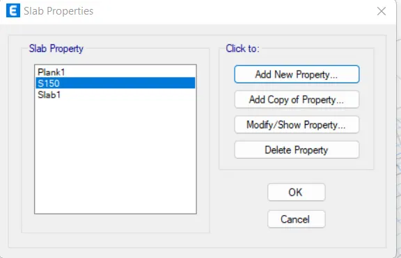
- And selecting slab section we need to add property and name the section as S150 and edit the section property
- And provide modeling type as membrane.then input the required slab thickness.
- Thus the slab is created.The created slab is to be used in all the models in this project.
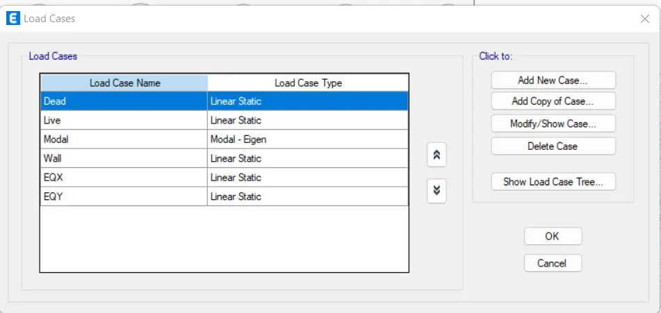
- The creating load patterns will be used in the rest of the models in the project.Add wall load, EQX and EQY.
- Other loads like Live load and Dead loads preexists in the software o we can add according to our requirement.
- EQX and EQY are assumed to be seismic loads and the load pattern reference is set to IS1893:2016.
- thus load pattern is shown below
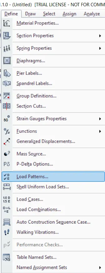
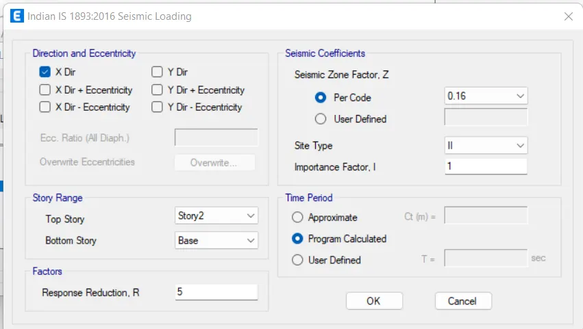
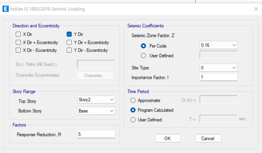
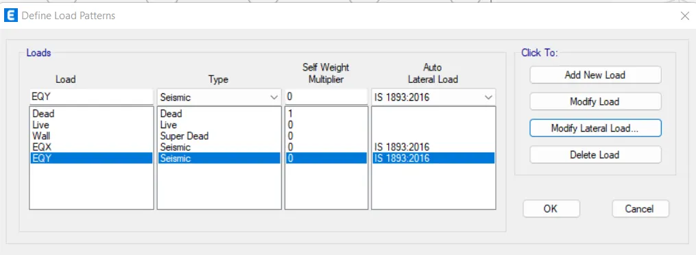
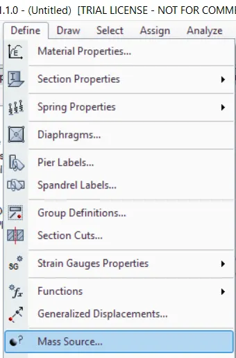
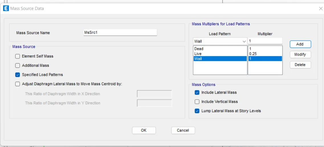
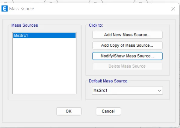
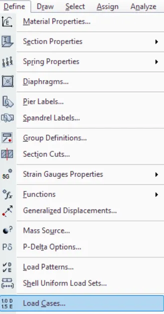
- After setting up teh lload pattern we need to set up mass source.
- In mass source we are setting up load multplier of the load pattern created.
- Thus created mass source is shown below.
- Hence the pre modelling settings are done and teh modelling of teh structural model can be stared.
- Now the model is started by placing the elements.Column sections are placed on the required grid points and the beams are placed on the grid lines .
- Both the columns and beams are placed by using quick draw tool.Thus the placed model is shown below.
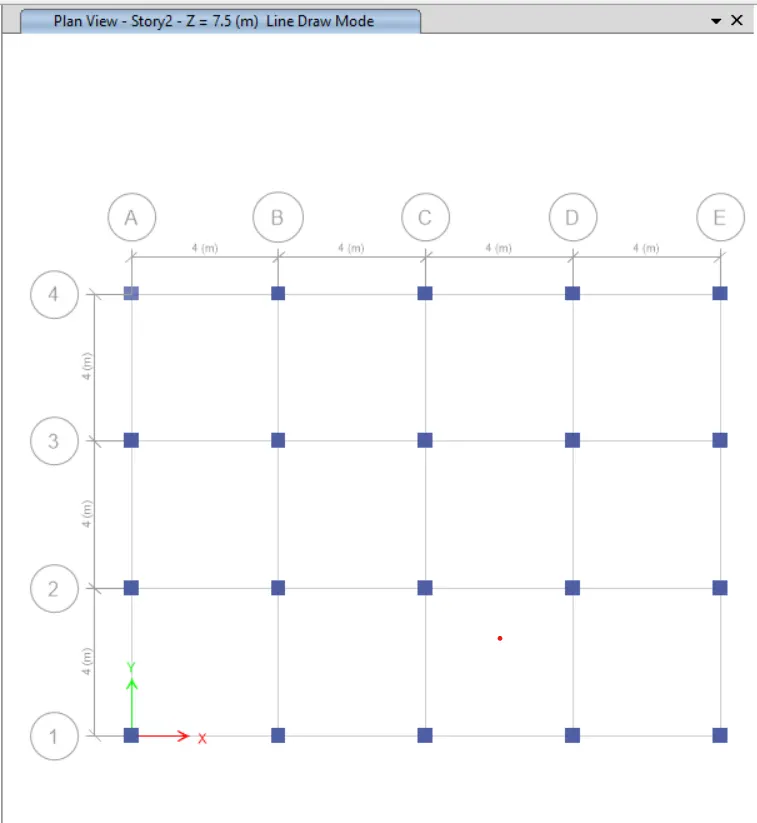
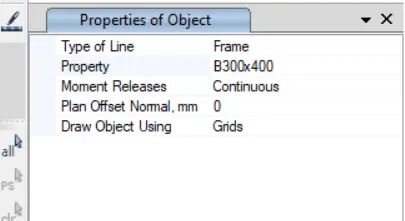

- Asign slab fot the structure ,select the similer story option because we dont want slab at plinth level
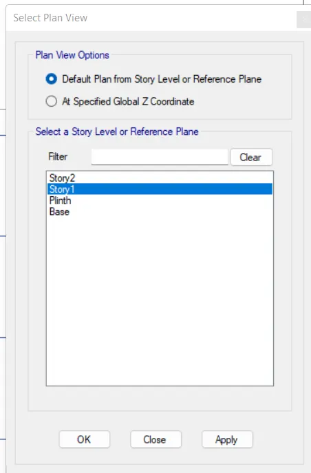
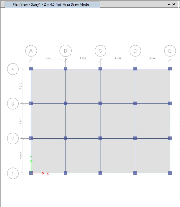
- click on Set plan View ,select Story 1
- Click on APPLY and OK
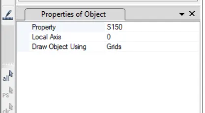
- Then go to the Quick Draw Slab Option ,properties dialogbox is open .From that select S150
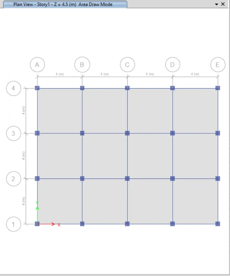
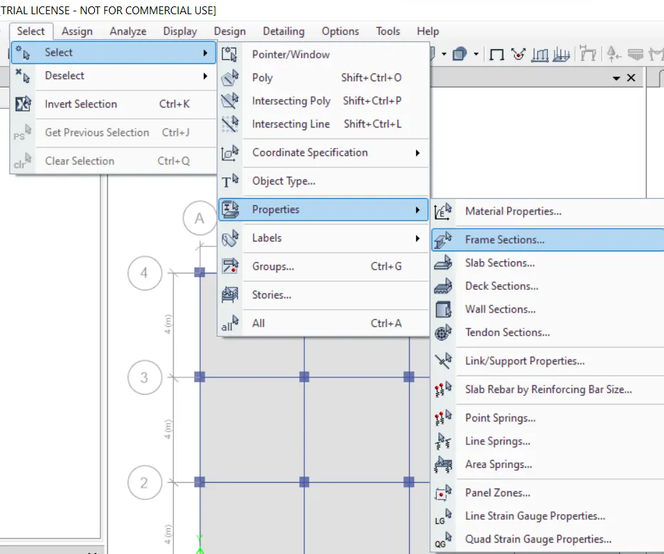
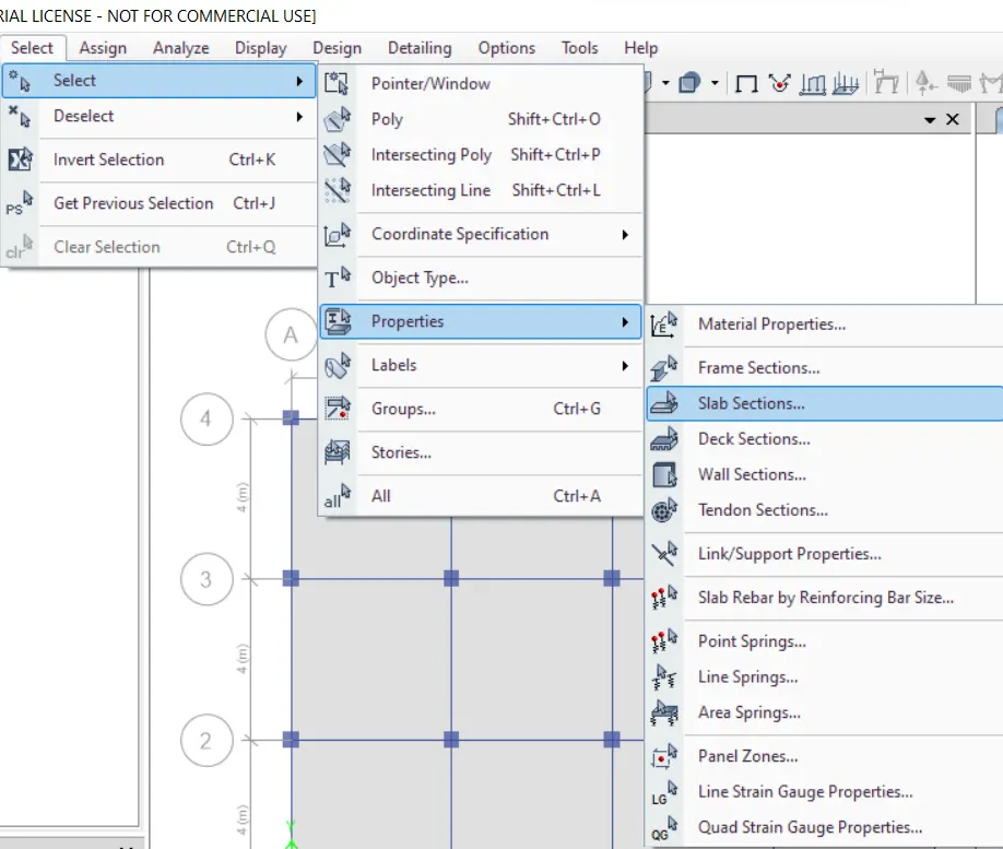
- Assign Loads for the structure,so that Go To The Select Option
- Click on Properties ,select the Frame section
- Select the Beam Properties shown below
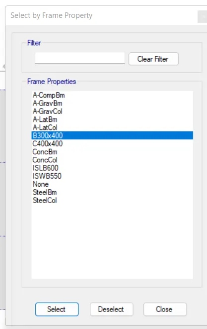
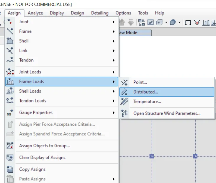
- Then go to assign tab,click on Frame Loads
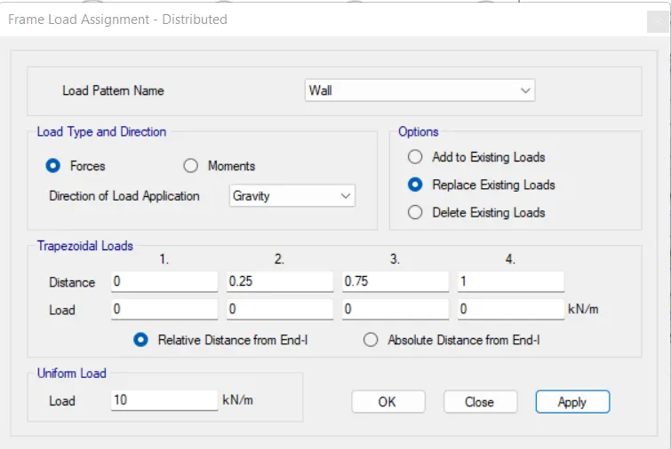
- then click on Distrubited, then one dialogbox is open
- fromthat select the load pattern as wall and give the wall load as 10 kN
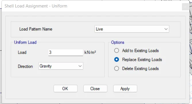
- apply 3 kN live load on slab , so that Click ON Select Option
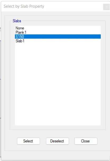
- then select properties and slab section
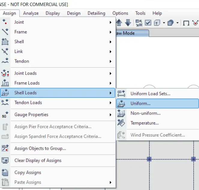
- select it and then close it,Then go to the Assign tab
- click on Shell Load, Then Uniform
- A dialog box is open as shown below form that select the load pattern as Live load and give the load as 3 KN.
- Assign diaphragms to calculate center of mass and rigidity of the structure is calculated .
- so that select the all slab and go to the select tab
- click on properties then slab section
- select the slab.
- then go to Assign tab and Click on Shell option
- then Click on Diaphragms select D1 option
- click on Apply and Then Ok
RUN ANALYSIS :
***************
Model B:
Step 1:
- Now to model building B, we need not create a new ETABS file from scratch.
- Rather we will save a copy of the building A file and do the alterations needed for building B.
- we can increase the number of stories to 5 by editing the story data within the copied file. So, the complete procedure to do so in ETABS is below
Step 2:
- Increase the story of the buildig
- Click on Edit ,edit story on grid
- one dialogbox will be open
Step 2:
- from this dialogbox click on,click on Modify/ Show story data
- one new dialogbox is open , click on add story
- add 3 more story
Step 3:
- Checked whether load is applyed or not
- so that click on Display Shell Load Assign , one dialogbox will be open
- select the load pattern as live load
- Then check the wall load, so that click on
- Display Frame Load Assign tab and select the load pattern as wall load
- Assign Diaphragms , so that first select the slab section
- click on Select tab and then properties and then slab section
- one dialogbox will be opened click oK
- click on Select
- then click on Assign tab , then click on Shell and then diaphragms
- one dialogbox will be opened then click on D1
- Then click on APPLY And then ok
Run Analysis
***************
Model C:
Step 1:
- The story and grid data for building c will remain still.
- we need to change the column size and orient the same in the X-direction.
- Change the column size of the building .so that , go to Define tab
- Then Section Properties , Then Frame Section one dialogbox is open
- click on c400x400
- then click on Modify/Show Properties
- new dialogbox is open
- From that give the name as C550x300
- depth of column is 550 and width of column is 300
- then click okand again one dialogbox is open
- from that click ok
Step 2:
- select the columns , for that go to Select tab
- then Properties , then frame section
- one new dialogbox is open
- click on Select option and then close
Step 3:
- Rotate the columns at 90 degree
- so that , Go to the assign tab then click on Frame and Then Local Axis
- one dialogbox is open click ok
- so that first select the slab section
- click on Select tab
- then properties and then slab section
- one dialogbox is open
- Selcect the slab , go to the Select tab
- then Properties Then Slab section , click on Slab150 and then click ok
- Select the diaphragms and go to Assign tab
- click on shell and then diaphragms
Run Analysis:
****************
Model D:
Step 1:
- In this model, we don't need to change anything other than the column orientation.
- The sizes of the column will remain the same,we have to shift the column orientation from X to Y direction.
- Click on File tab , Then click on Save As and Give the name of the file as Model D and then save it
- Change the column to Y axis.so that , first select the column
- click on Selct tab, then click on Properties and Frame Section
- Then click on c550x300 and select it and then close it .
Step 2:
- Change the direction x to Y, so that click on Assign tab
- click on Frame and then click on Local axis
- A dialog box is open from that change the angle 90 degree to 0 degree and click on APPLY and then ok
Step 3:
- Select the slab first and click on Select tab
- Then properties and then Slab section, select the S150 and then close it.
- Check for diaphragms and click on Assign tab
- Then shell option and then click on diaphragms and click on Apply and then OK
Run analysis :
***************
Model E:
Step 1:
- In this model, we need to add up 5 more storeys to our model.
- In addition, we also need to assign different column sizes on different floors.
- First save the ETABS file for building D as a new model as Model E.
- Then, edit the story data as we have done for our previous models in ETABS.
- Then, we need to add two new column sections with the required directions and assign them at appropriate floors in our model as specified.
- Add 5 more story in previous structure,so that go to the Edit option
- click on Edit Story And Grid System and one dialogbox will be appear
- from that click on Modify Story Data option and add 5 story there shown below
Step 2:
- Check the wall load and floor load of the structure
- click on Display shell load assign and select the load pattern as live load
- again click on Display Frame Load Assign and select the load pattern as wall load, Click on Apply and then OK
Step 3:
- Change the column size as 600x600 ,so that click on Define tab
- then Section properties and Frame section, select the c550x300
- click on Modify section and one dialogbox is open is shown below
- Give the property name as c600x600 and give the depth as 600 and width as 600
- click OK .
- Then Add one more new column size 400 x 400, so that click on Add new proprties
- Enter the name as c400x400 and then width of column as 400 and depth as 400
Step 4:
- Select the column only then hide the beam and floor
- click on set view point tab and unselect the beam and floor and then click ok
Step 5:
- Select the column from floor 6 to 10. So that , click on view tab and Then click on Set Building view Limits
- One dialogbox appears, from that select the Top story as Story 10 and base story as story 6
- Select the all columns, then click on Assign tab
- then click on Frame and then click on Section Properties, a dialogbox appears
- select the c400x400 and then click on APPY and then ok
Step 5:
- Then checked for diaphragms, so that select the slab first and go to the select option
- Then click on properties and slab section and a dialog box appears.
- click on seect and then close it, then click on Assign tab
- Then click on shell and then diaphragms, a dialog box will appear
- click on Appy and then OK
Run Analysis:
*************
Model F:
Step 1:
- Hide the beams and floor, so that click on Set Display Option and just unselect the Beams and floor
- click on Apply and then OK.
Step 2:
- Select the columns from story 6 to 10, so that click on View tab
- Set Building Limits then dialog box will appear
- from that click on story as 10 story and base story as 6 story
Step 3:
- Change the columns size as 600x600, so that select the columns
- click on Assign tab
- then click on Frame and then Section Properties
- then a dialob box appear from that click on c600x600 columns
- click on APPLY AND THEN OK .
- Then click on view tab, then click on Set Building View Limits
- A dialog box will appear,from that select the top story as 10 story and bottom as base story
Step 4:
- Again select the beams and floors, click on Set Display Option
- A dialog box will appear, from that click on Beam and slab and then click ok
Step 5:
- Check for diaphergram, for that first select the slab
- click on Select the tab and click on Properties
- Then Slab section, a dialog box appear
- select the slab150
- Then click on Assign tab
- click on Shell and the diaphergrm and click on D1
Run Analysis:
***************
Model G:
Step 1:
- Click on File menu and then click on Save As then file name as Model G
- Add more 15 story and click on Edit, then click on Edit Story And Grid System Data option
- A dialog box will appear
- from this click on Modify /Show Story data and add more 15 story
- click ok
Step 2:
- check the live load and wall loads of the structure
- Check Live load and click on Display Shell Load Assign and
- select the load pattern as Live load
- click on Apply and then OK .
- Check wall load ,click on Display Frame Load Assign tab
- A dialog box will appear, select the load pattern as wall load
Step 3:
- define columns as c400x400, c600X600 and c800x800 .
- Click on Define tab and then Frame section
- A dialog box will appear, create a new column as c800x800
Step 4:
- Apply different size of columns for each story, so that click first hide the beams and floors of the structure .
- click on Set Display View tab and unselect the beam and floors option
- click on Apply and then OK .
Step 5:
- Click on assign tab and then click on Frame and then Section Properties
- A dialog box will appear, select the c400x400
- Provide column size as 600x600 and click on View option, then click on Set Building Limits option
- A dialog box will appear and select the top story as story 20 and bottom story as story 11.
- click on OK and then click on Assign tab
- Then click on Frame and then Section Properties.
- again click on View Option
- click on set building view limits
- then Make visible beam and slab of the structure, click on Set Display Views Option and select the Beam and Slab Option and then click OK.
Step 6:
- select the slab click on Select tab
- then again click on Select and then properties , next is slab section
- A dialog box will appear ,click on Slab150
- click on Select and then closed it, click on Assign tab, select Shell and then Diaphragms
- A dialog box will appear, from that select D1
- click on APPLY and the OK
Run Analysis:
****************
Model H:
Step1:
- First click on File option , then click on Save as and Give the file name as Model H and the save it
Step 2:
- First hide the Beam and floor and the click on APPLY and the OK
Step 3:
- Assign all columns as 800x800, so that first select the columns
- Click on Assign tab, then click on Frame and then section properties
- A dialog box will appear, From that select c800x800
Step 4:
- Select the beam and slab and click on set display option
- Then select the beam , floor and diaphragms option
Run Analysis:
***************
Model J:
Step 1:
- Select all the slab and click on Select tab
- Then click on select tab then section properties and slab section
- A dialig box will appear, from that click on Slab150
- then click on Select and then close
Step 2:
- Increase the 10 % of live load and click on Assign tab
- then shell load, then click on Unifom
- A dialog box will appear and give the load as 3.3
Run Analysis:
******************
Model K:
Step 1:
- Click on File tab then click on Save as give the file name as Model K
- And then save it .
Step 2:
- Increase the live load by 20 %, click on Select tab and then again click on Select and then properties and then slab section .
- A dialog box will appear, select Slab150.
Step 3:
- Assign load, click on Assign tab
- Then click on Shell load select on Uniform
- A dialog box will appear, from that select the load pattern as live load and then give the load 3.6.
Run Analysis:
Result:
Model A:
Model B:
Model C:
Model D:
Model E:
MOdel F:
Model G:
Model H:
Model J:
Model K:
Criteria :
- Effect of stiffness on time period for Model E (10 Story with varying column size) : 1.73 s
- Effect of stiffness on time period for Model F (10 Story with uniform column size) : 1.74 s
- Effect of stiffness on time period for Model G (25 Story with varying column size) : 3.57s
- Effect of stiffness on time period for Model H (25 Story with uniform column size) : 3.57s
- Effect of mass on time period for Model H (25 Story with 3KN/m^2 imposed load) : 3.57s
- Effect of mass on time period for Model J(25 Story with 3.3KN/m^2 imposed load) : 3.57s
- Effect of mass on time period for Model K(25 Story with 3.6KN/m^2 imposed load) : 3.58s
- Effect of column orientation on time period for Model B (All floors column size 400x400) : 1.03s
- Effect of column orientation on time period for Model C (All floors column size 550x300 in X direction orientation) : 1.14s
- Effect of column orientation on time period for Model D (All floors column size 300x550 in Y direction orientation) : 1.12s
- Effect of flexural stiffness of structural elements on mode shape for Model B (Flexural stiffness of beams close to 0(Zero inertia) : 2.62s
- Effect of flexural stiffness of structural elements on mode shape for Model B(Flexural stiffness of beams(Regular) : 1.03s
- Effect of Axial stiffness of vertical members on mode shape for Model H (Axial cross section for columns is close to 0(Zero axial area) : 5.96s
- Effect of Axial stiffness of vertical members on mode shape for Model H (Axial cross section for columns(Regular) : 3.57s
- Effect of degree of fixity at column base on mode shape Model B (column support pinned(Regular) : 1.03s
- Effect of degree of fixity at column base on mode shape Model B (column support fixed : 0.941s
Conclusion:
- All the 10 buildings were modelled and analysed successfully.
- Suggested paramters and specifications were used.
- Analysis was run on the model using the Etabs
- And the results from the analysis was updated
****************